2021 ALFA ROMEO STELVIO lights
[x] Cancel search: lightsPage 121 of 280
119
System Status
Active System
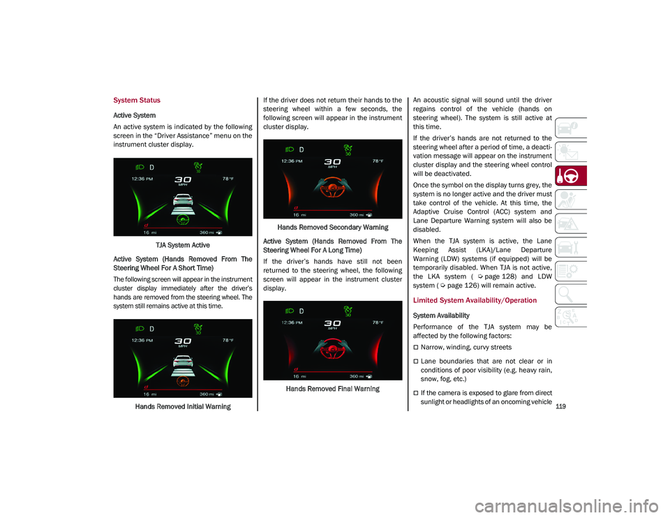
An active system is indicated by the following
screen in the “Driver Assistance” menu on the
instrument cluster display.TJA System Active
Active System (Hands Removed From The
Steering Wheel For A Short Time)
The following screen will appear in the instrument
cluster display immediately after the driver’s
hands are removed from the steering wheel. The
system still remains active at this time.
Hands Removed Initial Warning If the driver does not return their hands to the
steering wheel within a few seconds, the
following screen will appear in the instrument
cluster display.
Hands Removed Secondary Warning
Active System (Hands Removed From The
Steering Wheel For A Long Time)
If the driver’s hands have still not been
returned to the steering wheel, the following
screen will appear in the instrument cluster
display.
Hands Removed Final Warning An acoustic signal will sound until the driver
regains control of the vehicle (hands on
steering wheel). The system is still active at
this time.
If the driver’s hands are not returned to the
steering wheel after a period of time, a deacti
-
vation message will appear on the instrument
cluster display and the steering wheel control
will be deactivated.
Once the symbol on the display turns grey, the
system is no longer active and the driver must
take control of the vehicle. At this time, the
Adaptive Cruise Control (ACC) system and
Lane Departure Warning system will also be
disabled.
When the TJA system is active, the Lane
Keeping Assist (LKA)/Lane Departure
Warning (LDW) systems (if equipped) will be
temporarily disabled. When TJA is not active,
the LKA system (
Ú
page 128) and LDW
system (
Ú
page 126) will remain active.
Limited System Availability/Operation
System Availability
Performance of the TJA system may be
affected by the following factors:
Narrow, winding, curvy streets
Lane boundaries that are not clear or in
conditions of poor visibility (e.g. heavy rain,
snow, fog, etc.)
If the camera is exposed to glare from direct
sunlight or headlights of an oncoming vehicle
21_GU_OM_EN_USC_t.book Page 119
Page 131 of 280
129
Turning Lane Keeping Assist On Or Off
The system is activated/deactivated by pressing
the button at the end of the multifunction lever.
Each time the engine is started, the system main-
tains the operating mode that was selected when
it was previously turned off.
Activation/Deactivation Button
Activation Conditions
Once the activation button is pushed, the
system becomes active only if the following
conditions are met:
The car speed is higher than 37 mph
(60 km/h). (The system is deactivated at
speeds equal to or higher than 110 mph
(180 km/h))
The lane limit lines are visible at least on
one side
There are suitable visibility conditions
The road is straight or with wide radius
bends
A suitable distance is kept from the vehicle
in front
The turn signal (to indicate leaving the lane)
is not active
Lane Keeping Assist Warning Message
The Lane Keeping Assist system also advises
the driver when the car changes lanes by
showing symbols and messages on the instru -
ment cluster display.
The message at the top of the display remains
active only until the main reconfigurable area
of the display is activated by pressing the TRIP
button located on the end of the windshield
wiper lever
Ú
page 69.
After activating the main reconfigurable area,
the Lane Keeping Assist system messages will
be shown in the instrument cluster display.
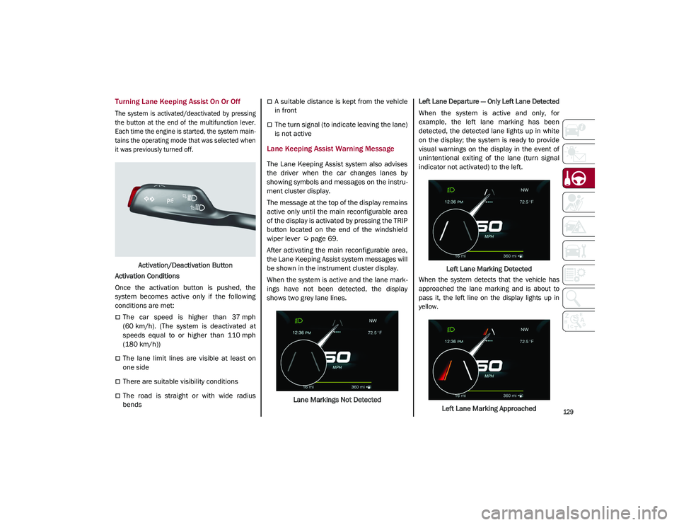
When the system is active and the lane mark -
ings have not been detected, the display
shows two grey lane lines.
Lane Markings Not Detected
Left Lane Departure — Only Left Lane Detected
When the system is active and only, for
example, the left lane marking has been
detected, the detected lane lights up in white
on the display; the system is ready to provide
visual warnings on the display in the event of
unintentional exiting of the lane (turn signal
indicator not activated) to the left.
Left Lane Marking Detected
When the system detects that the vehicle has
approached the lane marking and is about to
pass it, the left line on the display lights up in
yellow.
Left Lane Marking Approached
21_GU_OM_EN_USC_t.book Page 129
Page 142 of 280
STARTING AND OPERATING
140
Towing Requirements — Trailer Brakes
Do not interconnect the hydraulic brake
system or vacuum system of your vehicle
with that of the trailer. This could cause
inadequate braking and possible personal
injury.
An electronically actuated trailer brake
controller is required when towing a trailer
with electronically actuated brakes. When
towing a trailer equipped with a hydraulic
surge actuated brake system, an electronic
brake controller is not required.
Trailer brakes are recommended for trailers
over 1,000 lbs (453 kg) and required for
trailers in excess of 2,000 lbs (907 kg).
Towing Requirements — Trailer Lights And
Wiring
Whenever you pull a trailer, regardless of the
trailer size, stoplights and turn signals on the
trailer are required for motoring safety.
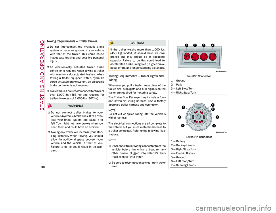
The Trailer Tow Package may include a four-
and seven-pin wiring harness. Use a factory
approved trailer harness and connector.
NOTE:
Do not cut or splice wiring into the vehicle’s
wiring harness.
The electrical connections are all complete to
the vehicle but you must mate the harness to
a trailer connector. Refer to the following illus -
trations.
NOTE:
Disconnect trailer wiring connector from the
vehicle before launching a boat (or any
other device plugged into vehicle’s elec -
trical connect) into water.
Be sure to reconnect once clear from water
area. Four-Pin Connector
Seven-Pin Connector
WARNING!
Do not connect trailer brakes to your
vehicle's hydraulic brake lines. It can over -
load your brake system and cause it to
fail. You might not have brakes when you
need them and could have an accident.
Towing any trailer will increase your stop -
ping distance. When towing, you should
allow for additional space between your
vehicle and the vehicle in front of you.
Failure to do so could result in an acci -
dent.
CAUTION!
If the trailer weighs more than 1,000 lbs
(453 kg) loaded, it should have its own
brakes and they should be of adequate
capacity. Failure to do this could lead to
accelerated brake lining wear, higher brake
pedal effort, and longer stopping distances.
1 — Ground
2 — Park
3 — Left Stop/Turn
4 — Right Stop/Turn
1 — Battery
2 — Backup Lamps
3 — Right Stop/Turn
4 — Electric Brakes
5 — Ground
6 — Left Stop/Turn
7 — Running Lamps
21_GU_OM_EN_USC_t.book Page 140
Page 143 of 280
141
Towing Tips
Before setting out on a trip, practice turning,
stopping, and backing up the trailer in an area
located away from heavy traffic.
Automatic Transmission
Select the DRIVE range when towing. The
transmission controls include a drive strategy
to avoid frequent shifting when towing.
However, if frequent shifting does occur while
in DRIVE, you can use the AutoStick shift
control to manually select a lower gear.
NOTE:
Using a lower gear while operating the vehicle
under heavy loading conditions will improve
performance and extend transmission life by
reducing excessive shifting and heat build-up.
This action will also provide better engine
braking.
Cruise Control — If Equipped
Do not use on hilly terrain or with heavy
loads.
When using the Cruise Control, if you expe-
rience speed drops greater than 10 mph
(16 km/h), disengage until you can get back
to cruising speed.
Use Cruise Control in flat terrain and with
light loads to maximize fuel efficiency.
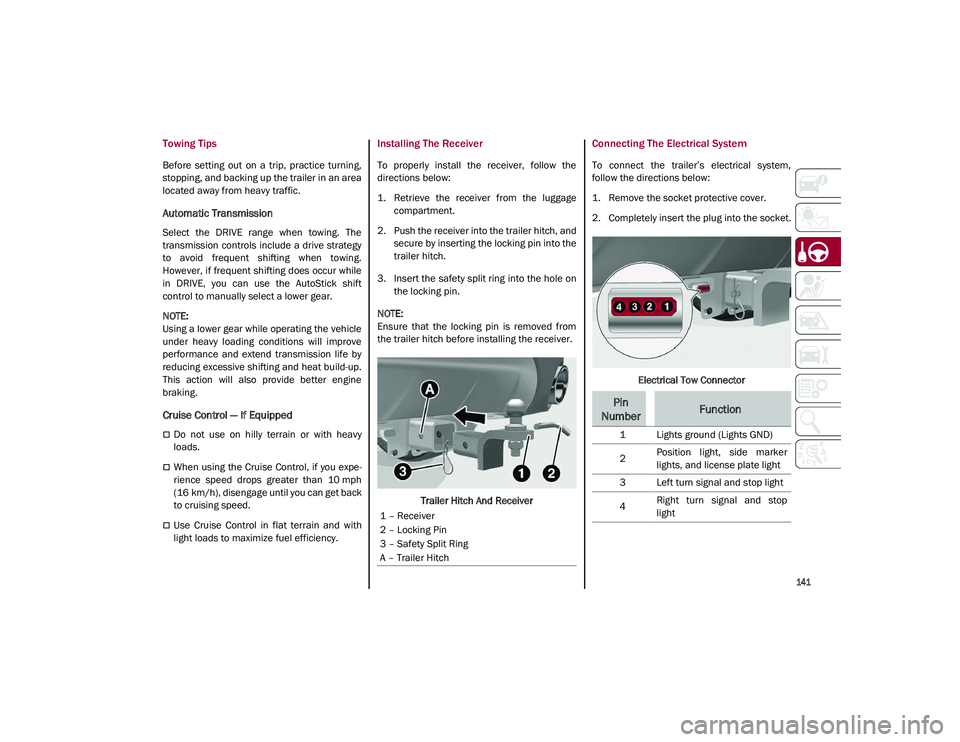
Installing The Receiver
To properly install the receiver, follow the
directions below:
1. Retrieve the receiver from the luggage compartment.
2. Push the receiver into the trailer hitch, and secure by inserting the locking pin into the
trailer hitch.
3. Insert the safety split ring into the hole on the locking pin.
NOTE:
Ensure that the locking pin is removed from
the trailer hitch before installing the receiver.
Trailer Hitch And Receiver
Connecting The Electrical System
To connect the trailer’s electrical system,
follow the directions below:
1. Remove the socket protective cover.
2. Completely insert the plug into the socket.
Electrical Tow Connector
1 – Receiver
2 – Locking Pin
3 – Safety Split Ring
A – Trailer Hitch
Pin
NumberFunction
1 Lights ground (Lights GND)
2 Position light, side marker
lights, and license plate light
3 Left turn signal and stop light
4 Right turn signal and stop
light
21_GU_OM_EN_USC_t.book Page 141
Page 144 of 280
STARTING AND OPERATING
142
Removing The Receiver
When the receiver is no longer needed, discon-
nect the electrical connections and remove it
from its position using the directions below:
1. Remove the safety split ring from the locking pin.
2. Pull the locking pin out of the trailer hitch.
3. Remove the receiver from the trailer hitch.
SUGGESTIONS FOR DRIVING
Saving Fuel
Below are some suggestions which may help
you save fuel and lower the amount of harmful
emissions released into the atmosphere.
Vehicle Maintenance
Checks and operations should be carried out
in accordance with the Maintenance Plan
Ú
page 208.
Tires
Check the tire pressures at least once every
four weeks: if the pressure is too low,
consumption levels increase as resistance to
rolling is higher.
NOTE:
Tire pressure that is too high can cause
premature tire wear, reduced control, etc. Unnecessary Loads
Do not travel with an overloaded liftgate. The
weight of the vehicle and its arrangement
greatly affect fuel consumption and stability.
Electric Devices
Use electrical systems only for the amount of
time needed. The rear window defroster, addi
-
tional headlights, windshield wipers and
heater blower fan require a considerable
amount of energy; increasing the current
uptake increases fuel consumption (by up to
+25% when city driving).
Climate Control System
Using the climate control system will increase
consumption: use standard ventilation when
the temperature outside permits.
Devices For Aerodynamic Control
The use of non-certified devices for aerody -
namic control may adversely affect air drag
and consumption levels.
Driving Style
Starting
Do not warm up the engine at low or high revs
when the vehicle is stationary; this causes the
engine to warm up more slowly, thereby
increasing fuel consumption and emissions. It
is therefore advisable to drive off immediately,
slowly, avoiding high speeds: by doing this the
engine will warm up more quickly. Unnecessary Actions
Avoid revving up when starting at traffic lights
or before stopping the engine. This action is
unnecessary and causes increased fuel
consumption and pollution.
Gear Selection
Use a high gear when traffic and road condi
-
tions allow it. Using a low gear for faster accel -
eration will increase fuel consumption.
Improper use of a high gear increases
consumption, emissions and engine wear.
Max. Speed
Fuel consumption considerably increases as
speed increases. Maintain a constant speed,
avoiding unnecessary braking and accelera -
tion, which cost in terms of both fuel consump -
tion and emissions.
Acceleration
Accelerating violently severely affects
consumption and emissions: acceleration
should be gradual and should not exceed the
maximum torque.Conditions Of Use
Cold Starting
Short trips and frequent cold starts will not
allow the engine to reach optimum operating
temperature. This results in a significant
increase in consumption levels (from +15 to
+30% in city driving) and emissions.
21_GU_OM_EN_USC_t.book Page 142
Page 145 of 280
143
Traffic And Road Conditions
High fuel consumption is caused by heavy
traffic, for instance when traveling in traffic
with frequent use of low gears or in cities with
many traffic lights. Winding mountain roads
and rough road surfaces also adversely affect
consumption.
Stops In Traffic
During prolonged stops (e.g. railway cross-
ings), turn off the engine.
Performance — Quadrifoglio
This vehicle is equipped with an engine
capable of delivering exceptionally fast accel -
eration and speed:
Peak power: 505 HP at 6,500 RPM.
Peak torque: 443 ft-lbs at 2,500–5,000 RPM.
Top speed: 176 mph (283 km/h).
Acceleration from 0 to 60 mph (0 to 100 km/h):
3.6 seconds.
For safe driving, it is essential, particularly
during the first days of use, to get to know the
car by driving carefully and gradually discov -
ering its performance.
Brakes
The car braking system may be available with
four carbon-ceramic material brake discs, one
on each wheel. In order to guarantee the maximum braking
capacity for the first use, Alfa Romeo performs
a "run-in" procedure for discs and pads directly
at the factory.
The use of carbon-ceramic material brake
discs guarantees braking features (better
deceleration/pedal load ratio, braking
distances, fading resistance) proportional to
the dynamic features of the car in addition to
considerably decreasing the unsprung compo
-
nent weight.
The materials used and the structural features
of the system could generate unusual noises
which have absolutely no adverse effect on
correct operation and reliability of the braking
system.
Greater pressure may need to be applied to
the brake pedal the first time to keep the same
braking capacities in presence of condensa -
tion or salt on the braking surfaces, for
example after washing or if the car is not used
for a long time.
NOTE:
Given the high technological level of this
system, any servicing on it must be performed
by an authorized dealer which exclusively has
the skills needed for the repair and mainte -
nance operations. In case of intensive, high-performance use of
the car, have the efficiency of the
carbon-ceramic material braking system
inspected as shown on the Maintenance Plan
at an authorized dealer.
Driving On Race Tracks
Before driving on a track using a racing style, it
is necessary to:
Attend a race track driving course.
Check the liquid levels in the engine
compartment
Ú
page 208.
Have the car inspected at an authorized
dealer.
Remember that the car was not designed to be
driven exclusively on the race track and that
this use increases stress and component
wear.
NOTE:
Quadrifoglio front brakes are equipped with
Non-Asbestos Organic (NAO) type pads. These
pads are NOT suitable for high thermal loads
(for example track use). If you want to use
vehicle on a track it is recommended to use
the optional CCM Brakes (Carbon Ceramic
Brake disc).
21_GU_OM_EN_USC_t.book Page 143
Page 174 of 280
SAFETY
172
damage by themselves are not good indicators
of whether or not an air bag should have
deployed.
Seat belts are necessary for your protection in
all collisions, and also are needed to help keep
you in position, away from an inflating air bag.
When the Occupant Restraint Controller (ORC)
detects a collision requiring the front air bags,
it signals the inflator units. A large quantity of
non-toxic gas is generated to inflate the front
air bags.
The steering wheel hub trim cover and the
upper passenger side of the instrument panel
separate and fold out of the way as the air
bags inflate to their full size. The front air bags
fully inflate in less time than it takes to blink
your eyes. The front air bags then quickly
deflate while helping to restrain the driver and
front passenger.
Knee Impact Bolsters
The Knee Impact Bolsters help protect the
knees of the driver and front passenger, and
position the front occupants for improved
interaction with the front air bags.
Supplemental Driver And Front Passenger
Knee Air Bags
This vehicle is equipped with a Supplemental
Driver Knee Air Bag mounted in the instrument
panel below the steering column and a
Supplemental Passenger Knee Air Bag
mounted in the instrument panel below the
glove compartment. The Supplemental Knee
Air Bags provide enhanced protection during a
frontal impact by working together with the
seat belts, pretensioners, and front air bags.
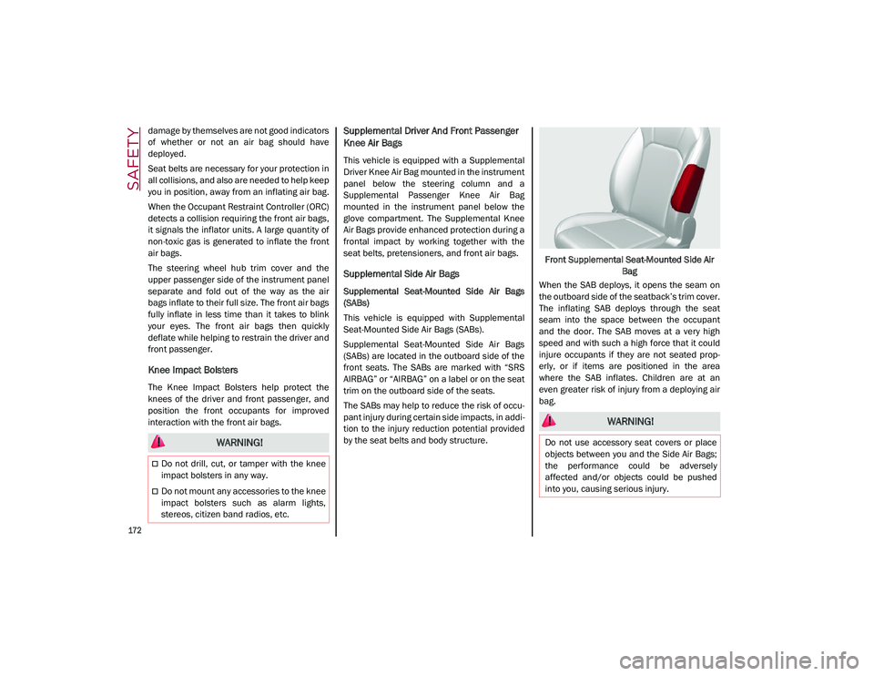
Supplemental Side Air Bags
Supplemental Seat-Mounted Side Air Bags
(SABs)
This vehicle is equipped with Supplemental
Seat-Mounted Side Air Bags (SABs).
Supplemental Seat-Mounted Side Air Bags
(SABs) are located in the outboard side of the
front seats. The SABs are marked with “SRS
AIRBAG” or “AIRBAG” on a label or on the seat
trim on the outboard side of the seats.
The SABs may help to reduce the risk of occu-
pant injury during certain side impacts, in addi-
tion to the injury reduction potential provided
by the seat belts and body structure. Front Supplemental Seat-Mounted Side Air
Bag
When the SAB deploys, it opens the seam on
the outboard side of the seatback’s trim cover.
The inflating SAB deploys through the seat
seam into the space between the occupant
and the door. The SAB moves at a very high
speed and with such a high force that it could
injure occupants if they are not seated prop -
erly, or if items are positioned in the area
where the SAB inflates. Children are at an
even greater risk of injury from a deploying air
bag.
WARNING!
Do not drill, cut, or tamper with the knee
impact bolsters in any way.
Do not mount any accessories to the knee
impact bolsters such as alarm lights,
stereos, citizen band radios, etc.
WARNING!
Do not use accessory seat covers or place
objects between you and the Side Air Bags;
the performance could be adversely
affected and/or objects could be pushed
into you, causing serious injury.
21_GU_OM_EN_USC_t.book Page 172
Page 177 of 280
175
If A Deployment Occurs
The front air bags are designed to deflate
immediately after deployment.
NOTE:
Front and/or side air bags will not deploy in all
collisions. This does not mean something is
wrong with the air bag system.
If you do have a collision which deploys the air
bags, any or all of the following may occur:
The air bag material may sometimes cause
abrasions and/or skin reddening to the
occupants as the air bags deploy and
unfold. The abrasions are similar to friction
rope burns or those you might get sliding
along a carpet or gymnasium floor. They are
not caused by contact with chemicals. They
are not permanent and normally heal
quickly. However, if you haven’t healed
significantly within a few days, or if you have
any blistering, see your doctor immediately.
As the air bags deflate, you may see some
smoke-like particles. The particles are a
normal by-product of the process that
generates the non-toxic gas used for air bag
inflation. These airborne particles may irri-
tate the skin, eyes, nose, or throat. If you
have skin or eye irritation, rinse the area
with cool water. For nose or throat irritation,
move to fresh air. If the irritation continues,
see your doctor. If these particles settle on
your clothing, follow the garment manufac -
turer’s instructions for cleaning. Do not drive your vehicle after the air bags
have deployed. If you are involved in another
collision, the air bags will not be in place to
protect you.
NOTE:
Air bag covers may not be obvious in the
interior trim, but they will open during air
bag deployment.
After any collision, the vehicle should be
taken to an authorized dealer immediately.
Enhanced Accident Response System
In the event of an impact, if the communica
-
tion network remains intact, and the power
remains intact, depending on the nature of the
event, the Occupant Restraint Controller (ORC)
will determine whether to have the Enhanced
Accident Response System perform the
following functions:
Cut off fuel to the engine (if equipped)
Cut off battery power to the electric motor (if
equipped)
Flash hazard lights as long as the battery
has power
Turn on the interior lights, which remain on
as long as the battery has power or for
15 minutes from the intervention of the
Enhanced Accident Response System
Unlock the power door locks
Your vehicle may also be designed to perform
any of these other functions in response to the
Enhanced Accident Response System:
Turn off the Fuel Filter Heater, Turn off the
HVAC Blower Motor, Close the HVAC Circula -
tion Door
Cut off battery power to the:
• Engine
• Electric Motor (if equipped)
• Electric power steering
• Brake booster
• Electric park brake
• Automatic transmission gear selector
• Horn
• Front wiper
• Headlamp washer pump
WARNING!
Deployed air bags and seat belt
pretensioners cannot protect you in another
collision. Have the air bags, seat belt
pretensioners, and the seat belt retractor
assemblies replaced by an authorized
dealer immediately. Also, have the
Occupant Restraint Controller System
serviced as well.
21_GU_OM_EN_USC_t.book Page 175