2021 ALFA ROMEO STELVIO brakes
[x] Cancel search: brakesPage 112 of 280
STARTING AND OPERATING
110
(Continued)
Setting The Distance Between Vehicles
The distance between your vehicle and the
vehicle ahead may be set to one bar (short),
two bars (medium), three bars (long), or four
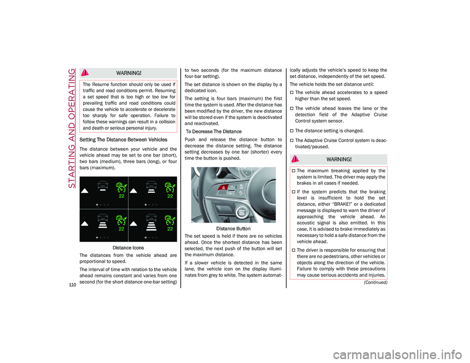
bars (maximum).Distance Icons
The distances from the vehicle ahead are
proportional to speed.
The interval of time with relation to the vehicle
ahead remains constant and varies from one
second (for the short distance one-bar setting) to two seconds (for the maximum distance
four-bar setting).
The set distance is shown on the display by a
dedicated icon.
The setting is four bars (maximum) the first
time the system is used. After the distance has
been modified by the driver, the new distance
will be stored even if the system is deactivated
and reactivated.
To Decrease The Distance
Push and release the distance button to
decrease the distance setting. The distance
setting decreases by one bar (shorter) every
time the button is pushed.
Distance Button
The set speed is held if there are no vehicles
ahead. Once the shortest distance has been
selected, the next push of the button will set
the maximum distance.
If a slower vehicle is detected in the same
lane, the vehicle icon on the display illumi -
nates from grey to white. The system automat -ically adjusts the vehicle’s speed to keep the
set distance, independently of the set speed.
The vehicle holds the set distance until:
The vehicle ahead accelerates to a speed
higher than the set speed.
The vehicle ahead leaves the lane or the
detection field of the Adaptive Cruise
Control system sensor.
The distance setting is changed.
The Adaptive Cruise Control system is deac
-
tivated/paused.
WARNING!
The Resume function should only be used if
traffic and road conditions permit. Resuming
a set speed that is too high or too low for
prevailing traffic and road conditions could
cause the vehicle to accelerate or decelerate
too sharply for safe operation. Failure to
follow these warnings can result in a collision
and death or serious personal injury.
WARNING!
The maximum breaking applied by the
system is limited. The driver may apply the
brakes in all cases if needed.
If the system predicts that the braking
level is insufficient to hold the set
distance, either “BRAKE!” or a dedicated
message is displayed to warn the driver of
approaching the vehicle ahead. An
acoustic signal is also emitted. In this
case, it is advised to brake immediately as
necessary to hold a safe distance from the
vehicle ahead.
The driver is responsible for ensuring that
there are no pedestrians, other vehicles or
objects along the direction of the vehicle.
Failure to comply with these precautions
may cause serious accidents and injuries.
21_GU_OM_EN_USC_t.book Page 110
Page 114 of 280
STARTING AND OPERATING
112
ahead. The offset vehicle may move in and out
of the line of travel, which can cause your
vehicle to brake or accelerate unexpectedly.
Turns And Bends
When driving on a curve with ACC engaged,
the system may increase or decrease the
vehicle speed for stability, with no vehicle
ahead detected. Once the vehicle is out of the
curve the system will resume your original set
speed. This is a part of normal ACC system
functionality.
NOTE:
On tight turns ACC performance may be
limited. In this case, it is advisable to deac-
tivate the system.
The system only limits the speed DURING a
bend and not BEFORE it.
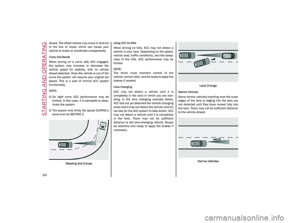
Steering And Curves
Using ACC On Hills
When driving on hills, ACC may not detect a
vehicle in your lane. Depending on the speed,
vehicle load, traffic conditions, and the steep -
ness of the hills, ACC performance may be
limited.
NOTE:
The driver must maintain control of the
vehicle, remain alert, and be ready to apply the
brakes if needed.
Lane Changing
ACC may not detect a vehicle until it is
completely in the lane in which you are trav -
eling. In the lane changing example below,
ACC has not yet detected the vehicle changing
lanes and it may not detect the vehicle until it's
too late for the ACC system to take action. ACC
may not detect a vehicle until it is completely
in the lane. There may not be sufficient
distance to the lane-changing vehicle. Always
be attentive and ready to apply the brakes if
necessary. Lane ChangeNarrow Vehicles
Some narrow vehicles traveling near the outer
edges of the lane or edging into the lane are
not detected until they have moved fully into
the lane. There may not be sufficient distance
to the vehicle ahead.
Narrow Vehicles
21_GU_OM_EN_USC_t.book Page 112
Page 115 of 280
113
Stationary Objects And Vehicles
The ACC system can detect stationary vehicles
when the vehicle is traveling at speeds
between 2 mph and 35 mph (4 km/h and
60 km/h). The driver should always be atten -
tive and be ready to press the brakes if neces -
sary.
Objects And Vehicles Moving In Opposite Or
Crosswise Direction
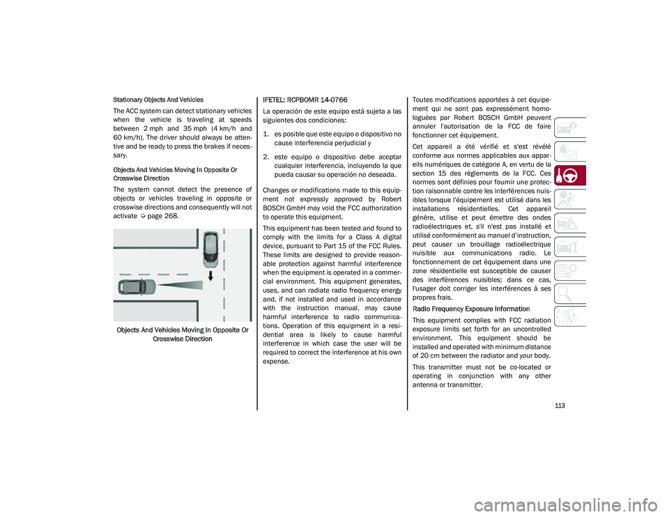
The system cannot detect the presence of
objects or vehicles traveling in opposite or
crosswise directions and consequently will not
activate
Ú
page 268.
Objects And Vehicles Moving In Opposite Or Crosswise Direction IFETEL: RCPBOMR 14-0766
La operación de este equipo está sujeta a las
siguientes dos condiciones:
1. es posible que este equipo o dispositivo no
cause interferencia perjudicial y
2. este equipo o dispositivo debe aceptar cualquier interferencia, incluyendo la que
pueda causar su operación no deseada.
Changes or modifications made to this equip -
ment not expressly approved by Robert
BOSCH GmbH may void the FCC authorization
to operate this equipment.
This equipment has been tested and found to
comply with the limits for a Class A digital
device, pursuant to Part 15 of the FCC Rules.
These limits are designed to provide reason -
able protection against harmful interference
when the equipment is operated in a commer -
cial environment. This equipment generates,
uses, and can radiate radio frequency energy
and, if not installed and used in accordance
with the instruction manual, may cause
harmful interference to radio communica -
tions. Operation of this equipment in a resi -
dential area is likely to cause harmful
interference in which case the user will be
required to correct the interference at his own
expense. Toutes modifications apportées à cet équipe
-
ment qui ne sont pas expressément homo -
loguées par Robert BOSCH GmbH peuvent
annuler l'autorisation de la FCC de faire
fonctionner cet équipement.
Cet appareil a été vérifié et s'est révélé
conforme aux normes applicables aux appar -
eils numériques de catégorie A, en vertu de la
section 15 des règlements de la FCC. Ces
normes sont définies pour fournir une protec -
tion raisonnable contre les interférences nuis -
ibles lorsque l'équipement est utilisé dans les
installations résidentielles. Cet appareil
génère, utilise et peut émettre des ondes
radioélectriques et, s'il n'est pas installé et
utilisé conformément au manuel d’instruction,
peut causer un brouillage radioélectrique
nuisible aux communications radio. Le
fonctionnement de cet équipement dans une
zone résidentielle est susceptible de causer
des interférences nuisibles; dans ce cas,
l'usager doit corriger les interférences à ses
propres frais.
Radio Frequency Exposure Information
This equipment complies with FCC radiation
exposure limits set forth for an uncontrolled
environment. This equipment should be
installed and operated with minimum distance
of 20 cm between the radiator and your body.
This transmitter must not be co-located or
operating in conjunction with any other
antenna or transmitter.
21_GU_OM_EN_USC_t.book Page 113
Page 125 of 280
123
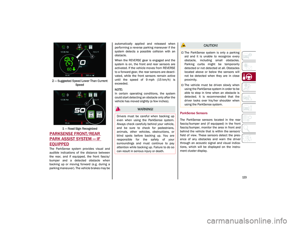
2 — Suggested Speed Lower Than Current Speed
1 — Road Sign Recognized
PARKSENSE FRONT/REAR
PARK ASSIST SYSTEM — IF
EQUIPPED
The ParkSense system provides visual and
audible indications of the distance between
the rear, and if equipped, the front fascia/
bumper and a detected obstacle when
backing up or moving forward (e.g. during a
parking maneuver). The vehicle brakes may be automatically applied and released when
performing a reverse parking maneuver if the
system detects a possible collision with an
obstacle.
When the REVERSE gear is engaged and the
system is on, the front and rear sensors are
activated. If the vehicle moves from REVERSE
to a forward gear, the rear sensors are deacti
-
vated, while the front sensors remain active
until the speed of 9 mph (15 km/h) is exceeded.
NOTE:
In certain operating conditions, the system
could start detecting an obstacle only after the
vehicle has moved slightly (a few inches).
ParkSense Sensors
The ParkSense sensors located in the rear
fascia/bumper and (if equipped) in the front
fascia/bumper, monitor the area in front and
behind the vehicle that is within the sensors’
field of view. These sensors detect the pres -
ence of any obstacles and warn the driver
through an acoustic signal and visual indica -
tions, which will be displayed on the instru -
ment cluster display.
WARNING!
Drivers must be careful when backing up
even when using the ParkSense system.
Always check carefully behind your vehicle,
and be sure to check for pedestrians,
animals, other vehicles, obstructions, or
blind spots before backing up. You are
responsible for the safety of your
surroundings and must continue to pay
attention while backing up. Failure to do so
can result in serious injury or death.
CAUTION!
The ParkSense system is only a parking
aid and it is unable to recognize every
obstacle, including small obstacles.
Parking curbs might be temporarily
detected or not detected at all. Obstacles
located above or below the sensors will
not be detected when they are in close
proximity.
The vehicle must be driven slowly when
using the ParkSense system in order to be
able to stop in time when an obstacle is
detected. It is recommended that the
driver looks over his/her shoulder when
using the ParkSense system.
21_GU_OM_EN_USC_t.book Page 123
Page 138 of 280
STARTING AND OPERATING
136
Gross Vehicle Weight Rating (GVWR)
The GVWR is the total permissible weight of
your vehicle including driver, passengers,
vehicle, options and cargo. The label also
specifies maximum capacities of front and
rear axle systems (GAWR). Total load must be
limited so GVWR and front and rear GAWR are
not exceeded.
Payload
The payload of a vehicle is defined as the
allowable load weight a truck can carry,
including the weight of the driver, all passen-
gers, options and cargo.
Gross Axle Weight Rating (GAWR)
The GAWR is the maximum permissible load
on the front and rear axles. The load must be
distributed in the cargo area so that the GAWR
of each axle is not exceeded.
Each axle GAWR is determined by the compo -
nents in the system with the lowest load
carrying capacity (axle, springs, tires or
wheels). Heavier axles or suspension compo -
nents sometimes specified by purchasers for
increased durability do not necessarily
increase the vehicle's GVWR.
Tire Size
The tire size on the Vehicle Certification Label
represents the actual tire size on your vehicle.
Replacement tires must be equal to the load
capacity of this tire size.
Rim Size
This is the rim size that is appropriate for the
tire size listed.
Inflation Pressure
This is the cold tire inflation pressure for your
vehicle for all loading conditions up to full
GAWR.
Curb Weight
The curb weight of a vehicle is defined as the
total weight of the vehicle with all fluids,
including vehicle fuel, at full capacity condi -
tions, and with no occupants or cargo loaded
into the vehicle. The front and rear curb weight
values are determined by weighing your
vehicle on a commercial scale before any
occupants or cargo are added.
Loading
The actual total weight and the weight of the
front and rear of your vehicle at the ground can
best be determined by weighing it when it is
loaded and ready for operation.
The entire vehicle should first be weighed on a
commercial scale to ensure that the GVWR
has not been exceeded. The weight on the
front and rear of the vehicle should then be
determined separately to be sure that the load
is properly distributed over the front and rear
axle. Weighing the vehicle may show that the
GAWR of either the front or rear axles has
been exceeded but the total load is within the specified GVWR. If so, weight must be shifted
from front to rear or rear to front as appro
-
priate until the specified weight limitations are
met. Store the heavier items down low and be
sure that the weight is distributed equally.
Stow all loose items securely before driving.
Improper weight distributions can have an
adverse effect on the way your vehicle steers
and handles and the way the brakes operate.
TRAILER TOWING
In this section you will find safety tips and
information on limits to the type of towing you
can reasonably do with your vehicle. Before
towing a trailer, carefully review this informa -
tion to tow your load as efficiently and safely
as possible.
To maintain the New Vehicle Limited Warranty
coverage, follow the requirements and recom -
mendations in this manual concerning vehi -
cles used for trailer towing.
CAUTION!
Do not load your vehicle any heavier than
the GVWR or the maximum front and rear
GAWR. If you do, parts on your vehicle can
break, or it can change the way your vehicle
handles. This could cause you to lose
control. Also overloading can shorten the
life of your vehicle.
21_GU_OM_EN_USC_t.book Page 136
Page 141 of 280
139
(Continued)
Consider the following items when computing
the weight on the rear axle of the vehicle:
The tongue weight of the trailer.
The weight of any other type of cargo or
equipment put in or on your vehicle.
The weight of the driver and all passengers.
NOTE:
Remember that everything put into or on the
trailer adds to the load on your vehicle. Also,
additional factory-installed options or
dealer-installed options must be considered
as part of the total load on your vehicle. Refer
to the “Tire And Loading Information” placard
for the maximum combined weight of occu -
pants and cargo for your vehicle.
Towing Requirements
To promote proper break-in of your new
vehicle drivetrain components, the following
guidelines are recommended:
Towing Requirements — Tires
Do not attempt to tow a trailer while using a
compact spare tire.
Do not drive more than 50 mph (80 km/h)
when towing while using a full size spare
tire.
Proper tire inflation pressures are essential
to the safe and satisfactory operation of
your vehicle.
Check the trailer tires for proper tire infla -
tion pressures before trailer usage.
Check for signs of tire wear or visible tire
damage before towing a trailer.
Replacing tires with a higher load carrying
capacity will not increase the vehicle's
GVWR and GAWR limits.
For proper tire inflation procedures
Ú
page 233.
WARNING!
Improper towing can lead to a collision.
Follow these guidelines to make your trailer
towing as safe as possible:
Make certain that the load is secured in
the trailer and that it will not shift during
travel. When trailering cargo that is not
fully secured, dynamic load shifts can
occur that may be difficult for the driver to
control. You could lose control of your
vehicle and have a collision.
When hauling cargo, or towing a trailer, do
not overload your vehicle or trailer. Over -
loading can cause a loss of control, poor
performance, or damage to brakes, axle,
engine, transmission, steering, suspen -
sion, chassis structure, or tires.
Safety chains must always be used
between your vehicle and trailer. Always
connect the chains to the frame or hook
retainers of the vehicle hitch. Cross the
chains under the trailer tongue and allow
enough slack for turning corners.
Vehicles with trailers should not be parked
on a grade. When parking, apply the
parking brake on the tow vehicle. Put the
tow vehicle transmission in PARK. Always
block or "chock" the trailer wheels.
GCWR must not be exceeded.
Total weight must be distributed between
the tow vehicle and the trailer such that
the following four ratings are not
exceeded:
• GVWR
• GTW
• GAWR
• Tongue weight rating for the trailer
hitch utilized.
WARNING! (Continued) CAUTION!
Do not tow a trailer at all during the first
500 miles (805 km) the new vehicle is
driven. The engine, axle or other parts
could be damaged.
Then, during the first 500 miles (805 km)
that a trailer is towed, do not drive over
50 mph (80 km/h) and do not make
starts at full throttle. This helps the engine
and other parts of the vehicle wear in at
the heavier loads.
21_GU_OM_EN_USC_t.book Page 139
Page 142 of 280
STARTING AND OPERATING
140
Towing Requirements — Trailer Brakes
Do not interconnect the hydraulic brake
system or vacuum system of your vehicle
with that of the trailer. This could cause
inadequate braking and possible personal
injury.
An electronically actuated trailer brake
controller is required when towing a trailer
with electronically actuated brakes. When
towing a trailer equipped with a hydraulic
surge actuated brake system, an electronic
brake controller is not required.
Trailer brakes are recommended for trailers
over 1,000 lbs (453 kg) and required for
trailers in excess of 2,000 lbs (907 kg).
Towing Requirements — Trailer Lights And
Wiring
Whenever you pull a trailer, regardless of the
trailer size, stoplights and turn signals on the
trailer are required for motoring safety.
The Trailer Tow Package may include a four-
and seven-pin wiring harness. Use a factory
approved trailer harness and connector.
NOTE:
Do not cut or splice wiring into the vehicle’s
wiring harness.
The electrical connections are all complete to
the vehicle but you must mate the harness to
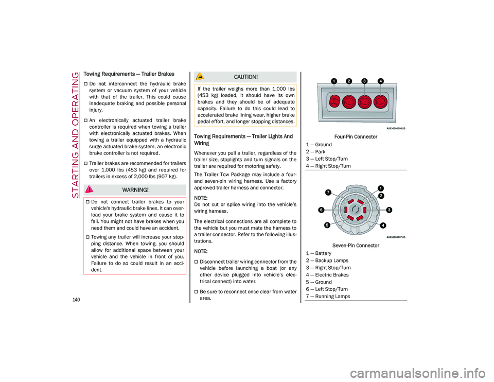
a trailer connector. Refer to the following illus -
trations.
NOTE:
Disconnect trailer wiring connector from the
vehicle before launching a boat (or any
other device plugged into vehicle’s elec -
trical connect) into water.
Be sure to reconnect once clear from water
area. Four-Pin Connector
Seven-Pin Connector
WARNING!
Do not connect trailer brakes to your
vehicle's hydraulic brake lines. It can over -
load your brake system and cause it to
fail. You might not have brakes when you
need them and could have an accident.
Towing any trailer will increase your stop -
ping distance. When towing, you should
allow for additional space between your
vehicle and the vehicle in front of you.
Failure to do so could result in an acci -
dent.
CAUTION!
If the trailer weighs more than 1,000 lbs
(453 kg) loaded, it should have its own
brakes and they should be of adequate
capacity. Failure to do this could lead to
accelerated brake lining wear, higher brake
pedal effort, and longer stopping distances.
1 — Ground
2 — Park
3 — Left Stop/Turn
4 — Right Stop/Turn
1 — Battery
2 — Backup Lamps
3 — Right Stop/Turn
4 — Electric Brakes
5 — Ground
6 — Left Stop/Turn
7 — Running Lamps
21_GU_OM_EN_USC_t.book Page 140
Page 145 of 280
143
Traffic And Road Conditions
High fuel consumption is caused by heavy
traffic, for instance when traveling in traffic
with frequent use of low gears or in cities with
many traffic lights. Winding mountain roads
and rough road surfaces also adversely affect
consumption.
Stops In Traffic
During prolonged stops (e.g. railway cross-
ings), turn off the engine.
Performance — Quadrifoglio
This vehicle is equipped with an engine
capable of delivering exceptionally fast accel -
eration and speed:
Peak power: 505 HP at 6,500 RPM.
Peak torque: 443 ft-lbs at 2,500–5,000 RPM.
Top speed: 176 mph (283 km/h).
Acceleration from 0 to 60 mph (0 to 100 km/h):
3.6 seconds.
For safe driving, it is essential, particularly
during the first days of use, to get to know the
car by driving carefully and gradually discov -
ering its performance.
Brakes
The car braking system may be available with
four carbon-ceramic material brake discs, one
on each wheel. In order to guarantee the maximum braking
capacity for the first use, Alfa Romeo performs
a "run-in" procedure for discs and pads directly
at the factory.
The use of carbon-ceramic material brake
discs guarantees braking features (better
deceleration/pedal load ratio, braking
distances, fading resistance) proportional to
the dynamic features of the car in addition to
considerably decreasing the unsprung compo
-
nent weight.
The materials used and the structural features
of the system could generate unusual noises
which have absolutely no adverse effect on
correct operation and reliability of the braking
system.
Greater pressure may need to be applied to
the brake pedal the first time to keep the same
braking capacities in presence of condensa -
tion or salt on the braking surfaces, for
example after washing or if the car is not used
for a long time.
NOTE:
Given the high technological level of this
system, any servicing on it must be performed
by an authorized dealer which exclusively has
the skills needed for the repair and mainte -
nance operations. In case of intensive, high-performance use of
the car, have the efficiency of the
carbon-ceramic material braking system
inspected as shown on the Maintenance Plan
at an authorized dealer.
Driving On Race Tracks
Before driving on a track using a racing style, it
is necessary to:
Attend a race track driving course.
Check the liquid levels in the engine
compartment
Ú
page 208.
Have the car inspected at an authorized
dealer.
Remember that the car was not designed to be
driven exclusively on the race track and that
this use increases stress and component
wear.
NOTE:
Quadrifoglio front brakes are equipped with
Non-Asbestos Organic (NAO) type pads. These
pads are NOT suitable for high thermal loads
(for example track use). If you want to use
vehicle on a track it is recommended to use
the optional CCM Brakes (Carbon Ceramic
Brake disc).
21_GU_OM_EN_USC_t.book Page 143