2021 ALFA ROMEO STELVIO spare tire location
[x] Cancel search: spare tire locationPage 198 of 280

IN CASE OF EMERGENCY
196
Changing Procedure
1. Park the vehicle on a firm, level surface.Avoid ice or slippery areas.
2. Turn on the Hazard Warning Flashers.
3. Apply the electric park brake.
4. Place the gear selector into PARK (P).
5. Place the ignition in the OFF mode.
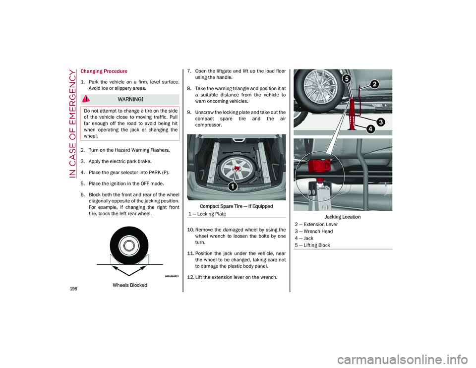
6. Block both the front and rear of the wheel diagonally opposite of the jacking position.
For example, if changing the right front
tire, block the left rear wheel.
Wheels Blocked 7. Open the liftgate and lift up the load floor
using the handle.
8. Take the warning triangle and position it at a suitable distance from the vehicle to
warn oncoming vehicles.
9. Unscrew the locking plate and take out the compact spare tire and the air
compressor.
Compact Spare Tire — If Equipped
10. Remove the damaged wheel by using the wheel wrench to loosen the bolts by one
turn.
11. Position the jack under the vehicle, near the wheel to be changed, taking care not
to damage the plastic body panel.
12. Lift the extension lever on the wrench. Jacking Location
WARNING!
Do not attempt to change a tire on the side
of the vehicle close to moving traffic. Pull
far enough off the road to avoid being hit
when operating the jack or changing the
wheel.
1 — Locking Plate
2 — Extension Lever
3 — Wrench Head
4 — Jack
5 — Lifting Block
21_GU_OM_EN_USC_t.book Page 196
Page 199 of 280

197
13. Rotate the extension lever clockwise untilthe round pin on the jack engages in the
hole in the lifting block located about
6 inches (15 cm) from the outside edge of
the body. The lifting points are marked by
triangles visible on the plastic body
panel.
Jacking Point Indicators
14. Raise the vehicle by turning the jack screw clockwise, using the swivel wrench. Raise
the vehicle only until the tire just clears the
surface and enough clearance is obtained
to install the compact spare tire. Minimum
tire lift provides maximum stability. 15. Remove the five wheel bolts and take the
wheel off.
16. Make sure the contact surfaces between compact spare tire and hub are clean so
that the fastening bolts will not come
loose.
17. Fit the compact spare tire by inserting the first wheel bolt for two threads into the
hole closest to the valve.
18. Take the wheel wrench and tighten the wheel bolts.
19. Inflate the compact spare tire by removing the cap from its inflation valve and
screwing on the compressor inflation hose
fitting. 20. Make sure that the switch on the
compressor is in the (off) O position, open
the liftgate and insert the plug into the
power socket in the cargo area, or on the
center console and start the engine. Place
the on/off switch in the (on) I position.
Attaching Compressor To Tire
21. Inflate the compact spare tire to a pres -
sure of 43.5 psi (3 bar).
NOTE:
If spare tire is overinflated, be sure to lower
the psi in the tire to the recommended amount
by using the deflation button on the air
compressor.
22. Operate the wheel wrench on the jack to lower the vehicle.
CAUTION!
Do not attempt to raise the vehicle by
jacking on locations other than those
indicated in the Jacking Instructions for this
vehicle.
WARNING!
Raising the vehicle higher than necessary
can make the vehicle less stable. It could
slip off the jack and hurt someone near it.
Raise the vehicle only enough to remove
the tire.
CAUTION!
Be sure to mount the spare tire with the
valve stem facing outward. The vehicle
could be damaged if the spare tire is
mounted incorrectly.
6 — Air Compressor
7 — Pressure Gauge
8 — Power Button
21_GU_OM_EN_USC_t.book Page 197
Page 200 of 280

IN CASE OF EMERGENCY
198
23. Remove the jack.
24. Use the wheel wrench to fully tighten thebolts, passing alternately from one bolt to
the diagonally opposite one.
To obtain a more accurate reading, it is advis -
able to check the pressure of the compact
spare tire on the pressure gauge with the
compressor off.
NOTE:
Do not stow the deflated tire in the compact
spare tire location.
The compressor was designed for inflating the
compact spare tire. Do not use it for inflating
mattresses, rafts, etc.
NOTE:
Spare tires are intended for temporary use
only.
Have the full-sized tire repaired or replaced, as
soon as possible.
TIRE SERVICE KIT — IF
EQUIPPED
Description
If a tire is punctured, you can make an emer -
gency repair using the Tire Service Kit located
in the rear storage area under the load plat -
form.
1. Stop the vehicle in a position where you can repair the tire safely. You should be as
far as possible from the side of the road,
and in a position that is not dangerous for
oncoming traffic. Turn on the Hazard
Warning Flashers, remove the safety
triangle from the luggage compartment,
and place it at a suitable distance from the
vehicle to make other drivers aware of
your presence.
2. Verify that the valve stem (on the wheel with the deflated tire) is in a position that
is near to the ground. This will allow the tire repair kit hoses to reach the valve stem
and keep the tire service kit flat on the
ground.
3. Place the gear selector in PARK (P).
4. Apply the electric park brake and turn the engine OFF.
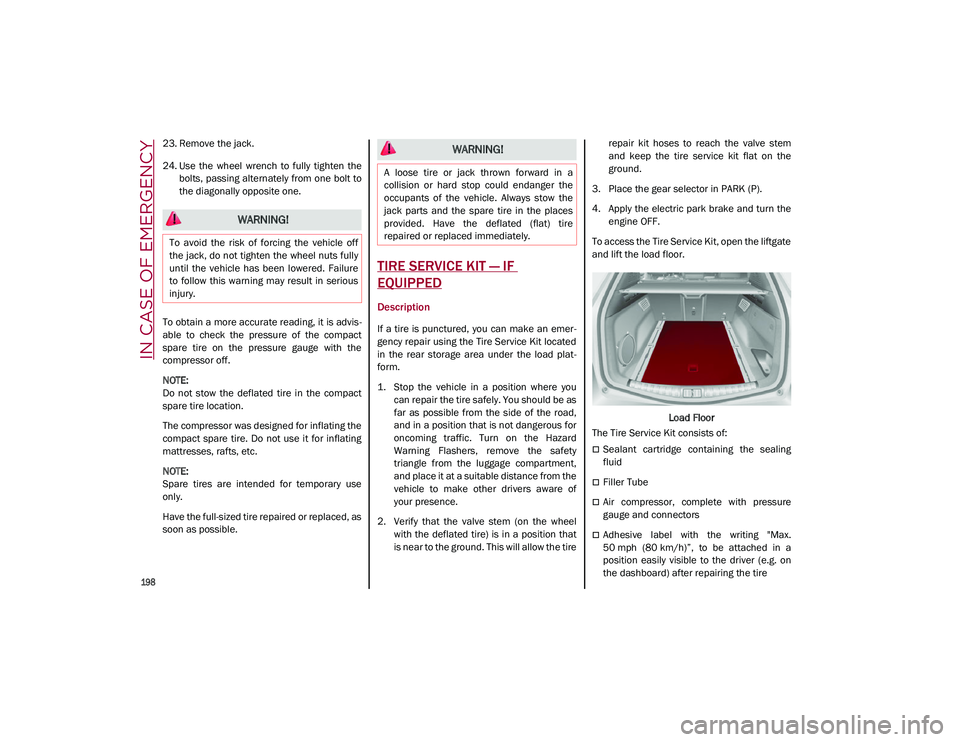
To access the Tire Service Kit, open the liftgate
and lift the load floor.
Load Floor
The Tire Service Kit consists of:
Sealant cartridge containing the sealing
fluid
Filler Tube
Air compressor, complete with pressure
gauge and connectors
Adhesive label with the writing "Max.
50 mph (80 km/h)”, to be attached in a
position easily visible to the driver (e.g. on
the dashboard) after repairing the tire
WARNING!
To avoid the risk of forcing the vehicle off
the jack, do not tighten the wheel nuts fully
until the vehicle has been lowered. Failure
to follow this warning may result in serious
injury.
WARNING!
A loose tire or jack thrown forward in a
collision or hard stop could endanger the
occupants of the vehicle. Always stow the
jack parts and the spare tire in the places
provided. Have the deflated (flat) tire
repaired or replaced immediately.
21_GU_OM_EN_USC_t.book Page 198
Page 239 of 280

237
Tire Loading And Tire Pressure
NOTE:
The proper cold tire inflation pressure is listed
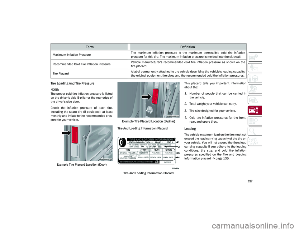
on the driver’s side B-pillar or the rear edge of
the driver's side door.
Check the inflation pressure of each tire,
including the spare tire (if equipped), at least
monthly and inflate to the recommended pres-
sure for your vehicle.
Example Tire Placard Location (Door) Example Tire Placard Location (B-pillar)
Tire And Loading Information Placard
Tire And Loading Information Placard This placard tells you important information
about the:
1. Number of people that can be carried in
the vehicle.
2. Total weight your vehicle can carry.
3. Tire size designed for your vehicle.
4. Cold tire inflation pressures for the front, rear, and spare tires.
Loading
The vehicle maximum load on the tire must not
exceed the load carrying capacity of the tire on
your vehicle. You will not exceed the tire's load
carrying capacity if you adhere to the loading
conditions, tire size, and cold tire inflation
pressures specified on the Tire and Loading
Information placard
Ú
page 135.
Maximum Inflation Pressure
The maximum inflation pressure is the maximum permissible cold tire inflation
pressure for this tire. The maximum inflation pressure is molded into the sidewall.
Recommended Cold Tire Inflation Pressure Vehicle manufacturer's recommended cold tire inflation pressure as shown on the
tire placard.
Tire Placard A label permanently attached to the vehicle describing the vehicle’s loading capacity,
the original equipment tire sizes and the recommended cold tire inflation pressures.
TermDefinition
21_GU_OM_EN_USC_t.book Page 237
Page 271 of 280

269
A
Accessories Purchased By The Owner.......... 4
Active Blind Spot Assist .............................152
Active Safety Systems ................................ 145
Active Torque Vectoring (ATV) System ......145
Adaptive Cruise Control (ACC)
(Cruise Control) .................................104, 106Off ........................................................... 108
On............................................................108
Additives, Fuel ............................................ 261
Adjust Forward.............................................. 31, 33
Rearward ........................................... 31, 33
Air Bag......................................................... 170 Air Bag Operation ...................................171Air Bag Warning Light ............................169
Driver Knee Air Bag................................ 172Enhanced Accident Response .....175, 207
Event Data Recorder (EDR) ...................207
Front Air Bag...........................................170
If Deployment Occurs ............................175
Knee Impact Bolsters ............................172
Maintaining Your Air Bag System.......... 177
Maintenance ..........................................177
Redundant Air Bag Warning Light.........170
Side Air Bags ..........................................172
Transporting Pets...................................189
Air Bag Light ......................................169, 189
Air Pressure Tires ........................................................240
Alfa Active Suspension (AAS).....................101
Alfa DNA System .......................................... 98
Antifreeze (Engine Coolant) ....................... 262
Anti-Lock Braking (ABS) System ................ 145
Anti-Lock Warning Light ............................... 75 Automatic Climate Controls ........................ 49
Automatic Dimming Mirror .......................... 37
Automatic Door Locks ................................. 27
Automatic Headlights .................................. 43
Automatic Temperature Control (ATC)........ 49
Automatic Transmission .............................. 92
Auxiliary Driving Systems .......................... 149
Auxiliary Power Outlet .................................. 56
B
Battery ................................................. 78, 217 Charging System Light ............................ 78
Keyless Key Fob Replacement ............... 18
Battery Recharging .................................... 218
Belts, Seat .................................................. 189
Blind Spot Monitoring ................................ 150
Bodywork (Cleaning And Maintenance) ... 249
B-Pillar Location ......................................... 237
Brake System Warning Light .....................................74, 75
Brakes ........................................................ 255 Brake Fluid Level ................................... 217
Brightness, Interior Lights ........................... 46
Bulbs, Light ................................................ 190
C
Camera, Rear ............................................. 132
Capacities, Fluid ........................................ 262
Carbon Monoxide Warning ............... 190, 191
Certification Label...................................... 135
Chart, Tire Sizing ........................................ 234
Check Engine Light (Malfunction
Indicator Light) ............................................. 85
Checking Levels ................................ 214, 215
Checking Your Vehicle For Safety ............. 188 Checks, Safety ........................................... 188
Child Restraint ........................................... 178
Child Restraints
Booster Seats ........................................ 180
Child Seat Installation........................... 187
How To Stow An unused ALR Seat Belt ..................................................... 185
Infant And Child Restraints................... 179
LATCH Positions .................................... 182
Lower Anchors And Tethers For Children ............................................. 181
Older Children And Child Restraints .... 179
Seating Positions................................... 181
Clean Air Gasoline ..................................... 260
Cleaning Wheels ................................................... 245
Climate Control ...................................... 48, 54 Automatic..................................................49
Compact Spare Tire................................... 245
Contract, Service ....................................... 267
Cooling System Cooling Capacity .................................... 262
Selection Of Coolant (Antifreeze) ......... 262
Cruise Control (Speed Control) ........ 104, 106
Customer Assistance ................................ 266
D
Daytime Running Lights ...............................42
Defroster, Windshield ............................... 189
Dimensions ................................................ 257
Disabled Vehicle Towing ........................... 205
Door Ajar ................................................ 79, 80
Door Ajar Light ....................................... 79, 80
Door Locks ....................................................27 Automatic..................................................27
21_GU_OM_EN_USC_t.book Page 269