Page 57 of 198
5-25
5
EBU31503Glove compartmentStore lightweight or frequently used items,
such as your driving gloves or vehicle docu-
ments, in this compartment.
NOTICEECB02071To protect from damage, do not put metal
items, like tools, or sharply edged items di-
rectly in the glove compartment. If they
must be stored, wrap them in appropriate
cushioning material. EBU38570Storage compartments
1. Unlock.
2. Open.Glove compartment load limit: 4.5 kg (9 lb)
1
2
1. Storage compartment
1
UB5J7BE0.book Page 25 Tuesday, June 18, 2019 10:07 AM
Page 58 of 198

5-26
5
When storing any documents in the storage
compartments, be sure to wrap them in a
plastic bag so that they will not get wet. When
washing the vehicle, be careful not to let any
water enter the storage compartments. To
access the underseat storage compartment,
remove the seat cushion. (See page 5-21.)
NOTICEECB02241To protect from damage, do not put metal
items, like tools, or sharply edged items di-
rectly in the storage compartment. If these
items must be stored, wrap them in appro-
priate cushioning material. EBU31520Cup holdersBe sure to tightly close the cap of any plastic
bottle before placing it in a cup holder.
Some plastic bottles may not fit into the cup
holders depending on their size and shape.
WARNING
EWB03240 Never ride with any open or glass con-
tainers in the cup holders; otherwise, the
contents may spill and the glass contain-
ers may be thrown about and break, and
possibly injure people in the vehicle dur-
ing sudden braking or an accident.
1. Storage compartment
1
UB5J7BE0.book Page 26 Tuesday, June 18, 2019 10:07 AM
Page 59 of 198
5-27
5
Do not place any other items than seal-
able plastic containers in the cup hold-
ers; otherwise, they may be thrown
about and possibly injure people in the
vehicle during sudden braking or an ac-
cident. EBU35022Cargo bed
WARNING
EWB03250Never carry passengers in the cargo
bed.
Do not exceed the specified maximum
load limits. Heavier cargo could cause
loss of control because of improper
weight balance.
There are four cargo hooks in the cargo bed.
For additional loading information, see page
7-9.
1. Cup holder
1
1. Cargo hookMaximum load limit: 136.0 kg (300 lb)
1
1
UB5J7BE0.book Page 27 Tuesday, June 18, 2019 10:07 AM
Page 60 of 198
5-28
5
EBU35660Flag pole bracketThis model is equipped with a flag pole brack-
et.NOTICEECB03010Do not use the flag pole bracket as a cargo
hook.
EBU35035Front shock absorbersThe shock absorber assemblies are equipped
with a spring preload adjusting nut, a rebound
damping force adjusting screw, a fast com-
pression damping force adjusting bolt, and a
slow compression damping force adjusting
screw.
WARNING
EWB02492Suspension components become hot
during operation. Never touch the com-
pression damping force adjusting bolt
and screw, the rebound damping force
adjusting screw or the oil reservoir with
your bare hand or skin until suspension
components have cooled.
Always adjust the shock absorber as-
semblies on the left and right side to the
same setting. Uneven adjustment can
cause poor handling and loss of stability,
which could lead to an accident.
1. Flag pole bracket
1
1
UB5J7BE0.book Page 28 Tuesday, June 18, 2019 10:07 AM
Page 61 of 198

5-29
5
NOTICEECB00091Never turn an adjusting mechanism be-
yond the minimum and maximum settings. TIPAlthough the total number of clicks or turns of
a damping force adjusting mechanism may
not exactly match the following specifications
due to small differences in production, the ac-
tual number of clicks or turns always repre-
sents the entire adjusting range. To obtain a
precise adjustment, it would be advisable to
check the number of clicks or turns of each
damping force adjusting mechanism and to
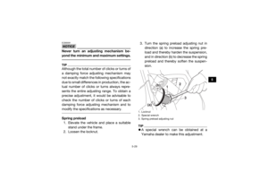
modify the specifications as necessary. Spring preload1. Elevate the vehicle and place a suitable
stand under the frame.
2. Loosen the locknut. 3. Turn the spring preload adjusting nut in
direction (a) to increase the spring pre-
load and thereby harden the suspension,
and in direction (b) to decrease the spring
preload and thereby soften the suspen-
sion.
TIPA special wrench can be obtained at a
Yamaha dealer to make this adjustment.1. Locknut
2. Special wrench
3. Spring preload adjusting nut
2
1
3
(a)
(b)
UB5J7BE0.book Page 29 Tuesday, June 18, 2019 10:07 AM
Page 62 of 198
5-30
5
The spring preload setting is determined by
measuring distance A, shown in the illustra-
tion. The shorter distance A is, the higher
the spring preload; the longer distance A is,
the lower the spring preload.
4. Tighten the locknut to the specified
torque. NOTICE: Always tighten the
locknut against the adjusting nut, and
then tighten it to the specified torque.
[ECB00082]
Spring preload setting: Minimum (soft):Distance A = 437.6 mm (17.23 in)
Standard: Distance A = 424.9 mm (16.73 in)
Maximum (hard): Distance A = 412.2 mm (16.23 in)
1. Distance ATightening torque:Locknut:41 N·m (4.1 kgf·m, 30 lb·ft)
1
UB5J7BE0.book Page 30 Tuesday, June 18, 2019 10:07 AM
Page 63 of 198
5-31
5
Rebound damping force
Turn the rebound damping force adjusting
screw in direction (a) to increase the rebound
damping force and thereby harden the damp-
ing, and in direction (b) to decrease the re-
bound damping force and thereby soften the
damping.
TIPWhen adjusting the damping force settings,
turn the adjuster in direction (a) until it stops,
and then count the turns or clicks in direction
(b). Compression damping force
Fast compression damping forceTo increase the fast compression damping
force and thereby harden the compression
damping, turn the fast compression damping
force adjusting bolt in direction (a). To de-
1. Rebound damping force adjusting screw
1
(a)(b)
Rebound damping setting: Minimum (soft):26 click(s) in direction (b)
Standard: 12 click(s) in direction (b)
Maximum (hard): 1 click(s) in direction (b)
UB5J7BE0.book Page 31 Tuesday, June 18, 2019 10:07 AM
Page 64 of 198
5-32
5
crease the fast compression damping force
and thereby soften the compression damp-
ing, turn the adjusting bolt in direction (b).Slow compression damping force
To increase the slow compression damping
force and thereby harden the compression
damping, turn the slow compression damp-
ing force adjusting screw in direction (a). To
decrease the slow compression damping for-
ce and thereby soften the compression
damping, turn the adjusting screw in direction
(b).
1. Fast compression damping force adjusting boltFast compression damping force settings:
Minimum (soft):4 turn(s) out from the fully turned in posi-
tion
Standard: 2 turn(s) out from the fully turned in posi-
tion
Maximum (hard): Adjusting bolt fully turned in
1
(a)
(b)
1. Slow compression damping force adjusting screw
1
(a)
(b)
UB5J7BE0.book Page 32 Tuesday, June 18, 2019 10:07 AM