Page 217 of 427

Multi Around Monitor (if so equipped) 5-136 Features and controls
5
N00587400060
Views of the surroundings of the vehicle and behind the vehicle are displayed. Views of the passenger’s side of the vehicle and behind the vehicle are displayed.
Views of the surroundings of the vehicle and the front of the vehicle are displayed.
Views of the passenger’s side of the vehicle and the front of the vehicle are displayed.
Types of views of the Multi Around Monitor
Bird’s eye-view/Rear-view mode
Side-view/Rear-view mode
Bird’s eye-view/Front-view mode
Side-view/Front-view mode
CAUTION The camera uses a special lens. As a result, images and distances shown on the screen are not exact.NOTE
Because the cameras have a special lens, the lines on the ground between parking spacesmay not look parallel on the screen. Under certain circumstances, it may become difficult to see an image on the screen, even when the system is
functioning correctly.
• In a dark area, such as at night. • When water drops or condensation are on the lens.
BK0277700US.book
136 ページ 2019年3月8日 金曜日 午前9時23分
Page 218 of 427

Multi Around Monitor (if so equipped)
Features and controls 5-137
5
N00587500074
The Multi Around Monitor can only be used when the operation mode is put in ON. When you move the selector lever to the “R” (REVERSE) position, the bird’s eye-view/rear-view is displayed on the Smart- phone Link Display A
udio. When you move
the selector lever to any other position, thedisplay disappears.
When the camera switch (A) is pressed, the bird’s eye-view/front-view is displayed.
If the camera switch is pressed, the mode of Multi Around Monitor is switched as follows. Bird’s eye-view/Rear-view mode
Side-
view/Rear-view mode If the camera switch is pressed, the mode of Multi Around Monitor is switched, Bird’s eye-view/Front-view mode
Side-
view/Front-view mode
OFF
• When sun light or headlights shine directly into the lens. • When a fluorescent light shines directly into the lens.
If the atmospheric temperature is extremely hot or extremely cold, the camera imagesmay not be clear. There is no abnormality. If a wireless device is installed near the cam- era, the camera images may cause electrical system interference and the system may stopfunctioning properly.
How to use the Multi Around Monitor
Operation with the selector lever
NOTE
NOTE
The passenger’s side screen can be switched to the side-view by pressing the camera switch on the steering wheel.
Operation with the switch
NOTE
If there is no operation for 3 minutes after the Multi Around Monitor is displayed by pressing the switch with the selector lever inother than “R” (REVERSE), the display dis- appears.
Switching of the screen (Selector lever is “R” (REVERSE))
Switching of the screen (Selector lever is other than “R” (REVERSE))
NOTE
When you move the selector lever to the “R” (REVERSE) position with the front-view mode displayed on the driver’s side screen,the driver’s side screen switches to the rear- view mode. When you shift the selector lever to any other position, the driver’s side screen switches to the front-view mode. When the camera switch
is pressed at the
vehicle speed of approximately 6 mph (10 km/h) or higher, only the side-view canbe displayed on the passenger’s side screen.
BK0277700US.book
137 ページ 2019年3月8日 金曜日 午前9時23分
Page 219 of 427

Multi Around Monitor (if so equipped) 5-138 Features and controls
5
N00587600059
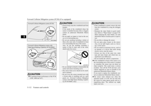
In any mode other than the Bird’s eye-view mode, the lines in the screen give the follow- ing information. Use them only as a guide. Reference lines for the distance and the vehi- cle width and upper surface of the front bum- per (A) are displayed on the screen. The Red line (B) indicates approximately 20 inches (50 cm) from the front edge of the front bumper.
The Two Green lines (C) indicate the approximate vehicle width. The Orange lines (D) indicates an expected course when the vehicle movesforward with the steering wheel turned. It disappears when the steering wheel is in the neutral position. The approximate distance from the vehi- cle body is as follows:
N00587700034
Reference lines for the distance and the vehi- cle width and upper surface of the rear bum-per (A) are displayed on the screen. The Red line (B) indicates approximately 20 inches (50 cm) behind the rear edge of the rear bumper. The Two Green lines (C) indicate the approximately vehicle width. The Orange line (D) indicates an expected course when the vehicle is reserved with the steering wheel turned. It disappears when the steering wheel is in the neutralposition. The approximate distance from the vehi- cle body is as follows:
The front-view will not be displayed when the vehicle speed exceeds approximately 6 mph (10 km/h). The display of the view may be delayed dur- ing switching of the screen.
How to read the screen
CAUTION If the camera and/or its surrounding area have experienced an impact, the Multi Around Monitor system may not functioncorrectly. Have the vehicle inspected by an authorized Mitsubishi Motors dealer.
Front-view mode
NOTE
1- Approximately 39 inches (100 cm) from
the front edge of the front bumperNOTE
When the expected course lines are dis- played in the front-view, the expected courselines are also displayed in the bird’s eye- view (Front: solid line, Rear: broken line).
Rear-view mode
NOTE
BK0277700US.book
138 ページ 2019年3月8日 金曜日 午前9時23分
Page 220 of 427

Multi Around Monitor (if so equipped)
Features and controls 5-139
5
1- Approximately 39 inches (100 cm)
from the rear edge of the rear bumper
2- Approximately 79 inches (200 cm)
from the rear edge of the rear bumperCAUTION The rear-view camera uses a wide-angle lens. As a result, images and distances shownon the screen are not exact. Never rely solely on the reference lines. The reference lines indicating distance and vehi- cle width are based on a level, flat road sur- face.Actual distance may be different from dis- tance indicated by the lines on the screen, depending on the loading condition of thevehicle and road surface condition. Also, your vehicle widt
h indicated by the
reference lines may be different from theactual vehicle width.
For example; In the following cases, objects shown on the screen will appear to be farther off than they actually are.• When the rear of the vehicle is weigheddown with the weight of passengers and luggage in the vehicle. A: Actual objects B: Objects shown on the screen• When there is an upward slope behind thevehicle. A: Actual objects B: Objects shown on the screenCAUTION
• When there is a downward slope behind the vehicle, objects shown on the screen will appear to be closer than they actually are. A: Actual objects B: Objects shown on the screenCAUTION
BK0277700US.book
139 ページ 2019年3月8日 金曜日 午前9時23分
Page 221 of 427
Multi Around Monitor (if so equipped) 5-140 Features and controls
5
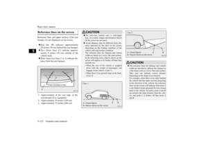
• When the vehicle is approaching a truck, the reference lines indicate that your vehi- cle will clear the truck. In reality, the truck is in your path.CAUTION
• When there is an object behind the vehiclethat has upper sections projecting in the direction of the vehicle, the reference lines on the screen will indicate that point A is the farthest point and point B is the closestpoint to the vehicle. In reality, point A and B are actually the same distance from the vehicle, and point C is farther off than pointA and B.CAUTION
NOTE
When the expected course lines are dis- played in the rear-view, the expected course lines are also displayed in the bird’s eye- view (Front: broken line, Rear: solid line).
BK0277700US.book
140 ページ 2019年3月8日 金曜日 午前9時23分
Page 222 of 427

Multi Around Monitor (if so equipped)
Features and controls 5-141
5
N00587900036
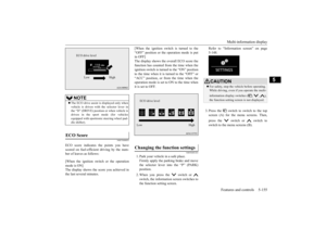
Reference lines for the vehicle width and the front end of the vehicle are displayed on thescreen.
N00588000034
An overhead view in which the vehicle islooked down is displayed so that you can eas-ily identify the location of your vehicle and the course to enter the parking space.
Side-view mode
1- Approximate vehicle width including
the door mirror.
2- Approximate location of the axle center
of the front wheel.
3- Approximate 20 inches (50 cm) from the
front edge of the front bumper.
Bird’s eye-view mode
CAUTION The bird’s eye-view is a composite image from images captured by the “Front-view camera”, “Side-view cameras (right and left)” and “Rear-view camera”. As a result, objects may appear to be farther away thanthey actually are. Also, an object may appear to be in a direction and/or location different from actual. In addition, blind spots exist inproximity of the vehicle. Even if the screen indicates that there is a space between your vehicle and an object,there may actually be less or no space. Always check visually behind and all around your vehicle. The view at a section
near each corner on the
Bird's eye-view is combined from the edgeof the view captured by each camera. As result, an object indicated in the section may be unclear, and it may disappear/reappear onthe screen.NOTE
In the Bird’s eye-view mode, since the views captured by the four cameras, “Front-view camera”, “Side-view cameras (right and left)” and “Rear-view camera” are processedbased on a level flat road surface, an image may be displayed as follows: • An object appears to have fallen down and looks longer or larger.
BK0277700US.book
141 ページ 2019年3月8日 金曜日 午前9時23分
Page 223 of 427

Instrument cluster 5-142 Features and controls
5
N00594200028
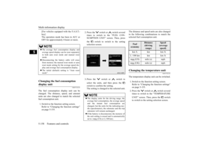
It is possible to change the vehicle icon color in the bird’s eye-view. 1. Stop the vehicle in a safe place.
2. Press the switch (A) to display the bird’s eye-view/front-view. 3. Press and hold down the switch (A) until the vehicle icon blinks to enter the selec- tion mode of the vehicle icon color in the bird’s eye-view.4. Press the switch until the desired color appears on the display. Each time you press the switch, the vehi-cle icon color in the bird’s eye-view willchange to the next one. 5. When it is changed to your desired color, press and hold the switch (A) for a fewseconds. This completes the setting.
N00519001444
• An object having a height from the road surface may seem to appear from the joint of the view composition processing regions.
The brightness of the views from each cam- era may vary depending on the illuminance conditions. An object above the camera is not displayed. The object displayed in the Front-view mode or the Rear-view mode may not be displayed in the Bird’s eye-view mode. The view in the Bird’s eye-view mode may be displaced from its true position when themounting location and angle of each camera are changed. The lines on the road may appear to be dis- placed or bent at the joint of the views.
To change the vehicle icon color in the bird’s eye-view
CAUTION For reasons of safety, do not operate the switch while driving.NOTE
NOTE
When the selection mode is in the following situations, the vehicle icon color does not change.
• When you place the gearshift lever or theselector lever in the “R” (REVERSE) posi- tion. • When you do not operate anything for 30 seconds. • The operation mode is put in OFF.
Instrument cluster 1- Tachometer
P.5-143
2- Multi-information display
P.5-144 Information screen display list
P.5-164
3- Speedometer
P.5-143
4- Rheostat illumination button
P.5-143NOTE
BK0277700US.book
142 ページ 2019年3月8日 金曜日 午前9時23分
Page 224 of 427

Instrument cluster
Features and controls 5-143
5
N00519101272
The speedometer shows the vehicle speed in miles per hour (mph) or kilometers per hour(km/h).
N00519201303
The tachometer shows engine revolutions perminute. This allows the driver to determinethe most efficient selector position and engine speed combinations. This gauge also assists in evaluating engineperformance.
N00554901293
Each time you press this button, there is asound and the brightness of the instrumentschanges.
Speedometer Type AType B
Tachometer
CAUTION The red zone indicates an engine speed beyond the range of safe operation. Select the correct selector position to control the engine speed so that the tachometer indi- cator does not enter the red zone.
Meter illumination control 1- Brightness level 2- Rheostat illumination button
NOTE
You can adjust to 8 different levels for when the front side-marker lights are illuminatedand when they are not. If the vehicle is equipped with the automatic light control, the light switch is in a position other than the “OFF” position and it is suffi- ciently dark outside the vehicle, the meterillumination switches automatically to the adjusted brightness.
BK0277700US.book
143 ページ 2019年3月8日 金曜日 午前9時23分