Page 129 of 228
 WARNING
148)If the replaced fuse blows again,
contact a Fiat Dealership.
149)Never replace a fuse with metal wires
or anything else.
150)Never replace a fuse with another with
a higher amp rating; DAN")
WARNING
148)If the replaced fuse blows again,
contact a Fiat Dealership.
149)Never replace a fuse with metal wires
or anything else.
150)Never replace a fuse with another with
a higher amp rating; DANGER OF FIRE.
151)If a general fuse (MEGA-FUSE,
MIDI-FUSE, MAXI-FUSE) blows contact a
Fiat Dealership.
152)Before replacing a fuse, make sure
that the ignition key has been removed and
that all the other services are switched off
and/or disengaged.
153)Contact Fiat Dealership if a safety
system (airbags, brakes), engine system
(engine, gearbox) or steering system
general protection fuse blows.
WARNING
52)If you need to wash the engine
compartment, take care not to directly hit
the engine compartment fuse box with
the water jet.
REPLACING A
WHEEL
GENERAL
INSTRUCTIONS
154) 155) 156) 157) 158) 159) 160) 161) 162)
JACK
Please note that:
the jack weight is 1.76 kg;
the jack requires no adjustment;
the jack cannot be repaired and in
the event of a fault it must be replaced
by another genuine one;
no tool other than its cranking
device may be fitted on the jack.
MAINTENANCE
prevent any dirt from depositing on
the "worm screw"
keep the "worm screw" lubricated
never modify the jack.
CONDITIONS OF
NON-USE
at temperatures lower than -40°C on
a sandy or muddy ground
on uneven ground
on steep roads
in extreme weather conditions:
thunderstorms, typhoons, hurricanes,
blizzards, storms, etc.
in direct contact with the engine or
for repairs under the car
on boats.
RAISING WITH A JACK
AND REPLACING A
WHEEL
To change a wheel, proceed as follows:
stop the car in a position that is
not dangerous for oncoming traffic
where you can change the wheel safely.
The ground must be flat and sufficiently
compact;
stop the engine, pull up the
handbrake and engage the first gear or
reverse. Wear the reflective safety
jacket (compulsory by law) before
getting out of the car;
raise the mat on the floor of the
luggage compartment;
undo the fastener B fig. 112;
take out the tool box C fig. 112 and
place it next to the wheel to be
changed;
take the space-saver wheel D fig.
112;
for vehicles with wheel cap: use the
screwdriver provided, applying leverage
to the dedicated opening on the outer
edge;
127
Page 130 of 228
 for cars equipped with 15\" steel
wheels with aesthetic hub caps: take
the extractor A fig. 113 from the Owner
Handbook compartment;
163)
hold the extractor with two fingers,
insert the tab between")
for cars equipped with 15" steel
wheels with aesthetic hub caps: take
the extractor A fig. 113 from the Owner
Handbook compartment;
163)
hold the extractor with two fingers,
insert the tab between the tyre and hub
cap A fig. 114 and pull towards
yourself, perpendicularly to the wheel;
for cars fitted with alloy wheels:
remove the press-fitted hub cap using
the screwdriver provided;
loosen the retaining bolts for the
wheel to be changed by about one turn
using the spanner provided;
if the car is equipped with side
skirts, to let the jack pass under the car,
the latter must be tilted (as shown in
fig. 115);
53)
turn the jack handle to partially open
it;
position the jack near the wheel to
be repaired at the reference point
on
the side member;
Lifting the front wheel: fig. 116.
Lifting the rear wheel: fig. 117.
make sure that the jack fig. 118 is
positioned correctly;
alert any bystander that the car is
about to be raised; all persons should
be kept away from the car and nobody
must touch it until it has been lowered;
112F0S0127
113F0S0671
114F0S0670
115F0S0328
116F0S0630
128
IN AN EMERGENCY
Page 131 of 228
 fit the handle to operate the jack and
raise the car until the wheel is a few
centimetres above the ground. When
turning the jack handle, make sure that
it can turn freely without scraping
your hand a")
fit the handle to operate the jack and
raise the car until the wheel is a few
centimetres above the ground. When
turning the jack handle, make sure that
it can turn freely without scraping
your hand against the ground. The
moving components of the jack (screws
and joints) can also cause injuries:
avoid touching them. If you come into
contact with lubricating grease, clean
yourself thoroughly;
loosen the bolts completely and
remove the wheel to be replaced;
make sure the contact surfaces
between space-saver wheel and hub
are clean so that the fastening bolts will
not come loose;
fit the space-saver wheel aligning
the pin with one of the holes on the
wheel;
screw in the 4 fastening bolts;
turn the jack handle to lower the car
and remove the jack;
fasten the bolts completely, passing
alternately from one bolt to the opposite
one.
REFITTING THE
STANDARD WHEEL
54)
Following the procedure described
previously, raise the car and remove the
space-saver wheel.
Versions with steel wheels
Proceed as follows:
make sure the contact surfaces
between standard wheel and hub are
clean so that the fastening bolts will not
come loose;
fit the standard wheel inserting the 4
bolts into the holes;
using the wrench provided, tighten
the fastening bolts;
lower the vehicle and remove the
jack;
use the wrench provided to fully
tighten the bolts, passing alternately
from one bolt to the opposite one;
insert the pressure-fit cup making
the suitable slot coincide with the
inflation valve;
place the inner part of the hub cap
on the wheel rim;
engage the hub cap by applying an
axial force in several points as shown
in fig. 119 to allow the correct coupling
between hub cap and wheel.
For cars equipped with 15" steel
wheels with aesthetic hub caps:
163)
once the normal wheel has been
fitted, insert the press-fit hub cap,
aligning the slot with the inflation valve;
117F0S0631
118F0S0653
119F0S0632
129
Page 132 of 228
 place the inner part of the hub cap
on the wheel rim;
engage the hub cap by applying an
axial force in several points as shown
in fig. 120 to allow the correct coupling
between hub cap and wheel.
Vers")
place the inner part of the hub cap
on the wheel rim;
engage the hub cap by applying an
axial force in several points as shown
in fig. 120 to allow the correct coupling
between hub cap and wheel.
Versions with alloy rims
Proceed as follows:
insert the wheel on the hub and use
the spanner provided to tighten the
bolts;
lower the vehicle and remove the
jack;
use the wrench provided to fully
tighten the bolts in an alternating
sequence;
reinsert the press-fitted hub cap,
making sure that the reference hole on
the wheel is aligned with the reference
pin on the cap.IMPORTANT If it is not fitted correctly,
the hub cap may detach when the
vehicle is running.
WARNING
154)The space-saver wheel (for
versions/markets where provided) is
specific to your car, do not use it on other
models, or use the space-saver wheel
of other models on your car. The
space-saver wheel must only be used in
the event of an emergency. Never use it for
more than strictly necessary and never
exceed 80 km/h.
155)On the space-saver wheel there is an
orange label, summarising the main
warnings regarding space-saver wheel
usage restrictions. Never remove or cover
the label. The label contains the following
indications in four languages: "Warning! For
temporary use only! 80 km/h max.!
Replace with standard wheel as soon as
possible. Never cover this indication."
Never apply a wheel cap on a space-saver
wheel.
156)If you change the type of wheel (alloy
rims instead of steel rims and vice versa)
you will have to change the entire set
of fastening bolts with another set of
suitably sized bolts.157)Alert other drivers that the car is
stationary in compliance with local
regulations: hazard warning lights, warning
triangle, etc. Any passengers on board
should leave the car, especially if it is
heavily laden. Passengers should stay
away from on-coming traffic while the
wheel is being changed. On hills or uneven
roads, use chocks or appropriate objects
to block the wheels of the vehicle.
158)The driving features of the car may
change when a space-saver wheel is fitted.
Avoid violent acceleration and braking,
abrupt steering and fast cornering. The
total life of a space-saver wheel is
approximately 3,000 km, after which it
must be replaced by another wheel of the
same type. Never install a traditional tyre
on a rim designed to be used as a
space-saver wheel. Have the wheel
repaired and refitted as soon as possible.
Using two or more space-saver wheels
at the same time is forbidden. Do not apply
grease to the bolt threads before fitting:
they could come unscrewed.
120F0S0669
130
IN AN EMERGENCY
Page 133 of 228
 159)The jack is a tool developed and
designed only for changing a wheel, if a
tyre gets punctured or damaged, on the
vehicle with which it is supplied or on other
vehicles of the same model. Any other")
159)The jack is a tool developed and
designed only for changing a wheel, if a
tyre gets punctured or damaged, on the
vehicle with which it is supplied or on other
vehicles of the same model. Any other
use, e.g. to jack up other vehicle models or
different things, is strictly prohibited. Never
use it to carry out maintenance or repairs
under the vehicle or to change summer/
winter wheels and vice versa. Never go
under the raised vehicle. If any work under
the vehicle is necessary, contact the Fiat
Service Network. Incorrect placing of
the jack can cause the vehicle to drop: use
it only in the positions indicated. Do not
use the jack for loads higher than the one
shown on its label. Never start the engine
with vehicle raised. If the vehicle is raised
more than necessary, everything can
become more unstable, with the risk of the
vehicle dropping violently. Thus, lift the
vehicle only as needed in order to access
the spare tyre.
160)Snow chains cannot be fitted to the
space-saver wheel. So, if a front (drive)
wheel is punctured and chains are needed,
a rear wheel should be fitted to the front
of the car and the space-saver wheel
should be fitted to the rear. In this way,
equipped with two normal drive wheels at
the front, they can be fitted with snow
chains, thus resolving the emergency
situation.
161)If the hub cap is not fitted correctly, it
may come off when the car is travelling.
Never tamper with the inflation valve. Never
introduce tools of any kind between rim
and tyre. Check tyre and space-saver
wheel pressures regularly, complying with
the values given in the "Technical
specifications" chapter.162)It is extremely dangerous to attempt
to change a wheel on the side of the
vehicle next to the driving lane: make sure
that the vehicle is at a sufficient distance
from the road, to avoid being run over.
163)Be very careful when removing/
refitting the hub cap due to the proximity of
the brake disc. We recommend using
heat protection gloves.
WARNING
53)When turning the jack handle make
sure that it can turn freely without scraping
your hand against the ground. The moving
components of the jack ("worm screw"
and joints) can also cause injuries: do not
touch them. If you come into contact
with lubricating grease, clean yourself
thoroughly.
54)Contact a Fiat Dealership as soon as
possible to have the correct tightening
of the wheel bolts checked.
Fix&Go kit
(where provided)
164) 165)
55)
DESCRIPTION
The Fix&Go quick tyre repair kit fig. 121
is located in the boot, inside a
dedicated container and consists of:
one cartridge 1 containing sealant
and fitted with: transparent tube for
injecting the sealant 4 and sticker
3 with the wording “Max 80 km/h” to
be placed in a clearly visible position
(e.g. on the dashboard) after repairing
the tyre;
one compressor 2;
one leaflet containing instructions for
using the kit;
a pair of gloves located in the hose
compartment of the cartridge 4.
121P2000158
131
Page 134 of 228
 REPAIR PROCEDURE
Proceed as follows:
stop the car in a position that is not
dangerous for oncoming traffic where
you can carry out the procedure safely.
The ground must be flat and sufficiently
compac")
REPAIR PROCEDURE
Proceed as follows:
stop the car in a position that is not
dangerous for oncoming traffic where
you can carry out the procedure safely.
The ground must be flat and sufficiently
compact;
stop the engine, engage the hazard
warning lights and the parking brake;
wear the reflective safety jacket
before getting out of the car (anyway
comply with the laws in force in the
country you are driving in);
Insert the cartridge 1 containing the
sealant in the proper compartment of
the compressor 2, pressing it down
hard fig. 121. Remove the speed limit
sticker 3 and apply it in a clearly visible
position fig. 122;
wear the gloves;
remove the cap from the tyre valve
and connect and firmly tighten the
transparent tube of the sealing fluid 4
fig. 121. If a 250 ml cartridge is present
the housing of the transparent tube is
provided with removable ring to
facilitate extraction. Make sure that the
ON-OFF button 5 fig. 123 is in the off
position (button not pressed);
plug the electric connector 3 fig. 124
into the 12V socket of the vehicle and
start the vehicle engine;
operate the compressor by pressing
the ON-OFF button 5 fig. 123. When
the pressure shown in the "Wheels"
paragraph in the “Technical data”
chapter or on the specific label appears
on the pressure gauge 7, stop the
compressor by pressing the ON-OFF
button 5 again;
disconnect the cartridge 1 from the
compressor, by pressing the release
button 8 and lifting the cartridge 1
upwards fig. 125.
122P2000162
123P2000160
124P2000159
125P2000161
132
IN AN EMERGENCY
Page 135 of 228
 If the pressure gauge 7 fig. 123
indicates a pressure lower than 1.8 bar
/ 26 psi 15 minutes after starting the
compressor, switch off the compressor,
disconnect the sealing fluid tube 4
from the tyre")
If the pressure gauge 7 fig. 123
indicates a pressure lower than 1.8 bar
/ 26 psi 15 minutes after starting the
compressor, switch off the compressor,
disconnect the sealing fluid tube 4
from the tyre valve and remove
the cartridge 1 from the compressor fig.
121. Move the vehicle by approximately
10 m to promote the distribution of
sealant; stop the vehicle safely, operate
the handbrake and restore pressure
using the black inflation pipe 9 fig. 126
to reach the required pressure. If also
in this case, the pressure is lower
than 1.8 bar / 26 psi 15 minutes after
turning on, do not resume driving
but contact a Fiat Dealership.After driving for about 8 km / 5 miles,
position the vehicle in a safe and
suitable area and engage the
handbrake. Take the compressor and
restore pressure using the black
inflation tube 9 fig. 126.
If the pressure shown is higher than 1.8
bar / 26 psi, restore the pressure and
drive safely to a Fiat Dealership as soon
as possible.
If, however, the pressure is lower than
1.8 bar / 26 psi, do not resume driving
but contact a Fiat Dealership.
PROCEDURE FOR
RESTORING THE
PRESSURE
Proceed as follows:
stop the vehicle safely, as shown
above, and operate the handbrake;
extract the black inflation tube 9 fig.
126 and screw it firmly onto the tyre
valve. Follow the instructions shown in
fig. 124 and fig. 126.
Press the air release button 10 fig. 123
to adjust any tyre overpressure.
CARTRIDGE
REPLACEMENT
Proceed as follows:
only use original Fix&Go cartridges,
which can be purchased from the
Fiat Dealership.
to remove the cartridge,fig. 125
press the release button 8 and lift it.
WARNING
164)The information required by the
applicable regulation is indicated on the
Fix&Go kit package label. Carefully read
the label on the cartridge before use, avoid
improper use. The kit should be used by
adults and cannot be used by children.
165)IMPORTANT: Do not exceed 80 km/h.
Avoid sudden acceleration or braking.
The kit provides a temporary repair,
therefore the tyre must be examined and
repaired by a specialist as soon as
possible. Before using the kit, ensure that
the tyre is not excessively damaged and
that the rim is in good condition, otherwise
do not use it and call roadside assistance.
Do not remove foreign bodies from the
tyre. Do not let the compressor turned on
for more than 20 consecutive minutes -
overheating hazard.
WARNING
55)The sealant fluid is effective with
external temperatures between -40°C and
+55°C. The sealant fluid has an expiry
date. It is possible to repair tyres which
have been damaged on tread up to a
diameter of 6 mm. Show the cartridge and
the label to the personnel charged with
handling the tyre treated with the tyre
repair kit.
126P2000163
133
Page 136 of 228
 JUMP STARTING
If the battery is flat, a jump starting can
be performed using the battery and
the cables of another car, or using an
auxiliary battery. In all cases, the battery
used must have a capaci")
JUMP STARTING
If the battery is flat, a jump starting can
be performed using the battery and
the cables of another car, or using an
auxiliary battery. In all cases, the battery
used must have a capacity equal to or
a little higher than the flat one.
Jump starting may be dangerous if
carried out incorrectly: carefully follow
the procedures described below.
IMPORTANT NOTES
After turning the ignition key to STOP
and having closed the driver's side
door, wait at least one minute before
disconnecting the battery and then
reconnecting the electrical supply to the
battery.
Do not use an auxiliary battery or any
other source of external supply with
a voltage above 12 V: the battery, the
starter, the alternator and the electrical
system of the car could be damaged.
Do not attempt jump starting if the
battery is frozen. The battery could
break and explode!JUMP STARTING166) 167) 168)
56) 57) 58)
If the battery is flat, the engine may be
started using an auxiliary battery fig.
127, with the same capacity or a little
higher than the flat one.
Proceed as follows to start the car:
connect the positive terminals (+
mark near the terminal) of the two
batteries using a suitable lead;
with a second lead, connect the
negative terminal – of the auxiliary
battery to an earth point
on
the engine or the gearbox of the car to
be started;
start the engine;
when the engine has been started,
remove the leads reversing the order
above.For versions with Start&Stop
In the case of emergency starting,
NEVER connect the negative lead (–) of
the auxiliary battery to negative pole
(–) of the battery, but only to an earth
point on the engine/gearbox assembly.
If after a few attempts the engine does
not start, do not persist but contact
a Fiat Dealership.
IMPORTANT Do not directly connect
the negative terminals of the two
batteries: sparks could ignite explosive
gas released from the battery. If the
auxiliary battery is installed on another
car, prevent accidental contact
between metallic parts of the two cars.
BUMP STARTING
Never bump start the engine by
pushing, towing or driving downhill.
This could cause fuel to flow into the
catalytic converter and damage it
beyond repair.
IMPORTANT Remember that the brake
servo and electrical power steering
system (for versions/markets, where
provided) are not active until the engine
is started. A much greater effort will
therefore be required to use the brake
pedal or turn the steering wheel.
127F0S0093
134
IN AN EMERGENCY
 1
1 2
2 3
3 4
4 5
5 6
6 7
7 8
8 9
9 10
10 11
11 12
12 13
13 14
14 15
15 16
16 17
17 18
18 19
19 20
20 21
21 22
22 23
23 24
24 25
25 26
26 27
27 28
28 29
29 30
30 31
31 32
32 33
33 34
34 35
35 36
36 37
37 38
38 39
39 40
40 41
41 42
42 43
43 44
44 45
45 46
46 47
47 48
48 49
49 50
50 51
51 52
52 53
53 54
54 55
55 56
56 57
57 58
58 59
59 60
60 61
61 62
62 63
63 64
64 65
65 66
66 67
67 68
68 69
69 70
70 71
71 72
72 73
73 74
74 75
75 76
76 77
77 78
78 79
79 80
80 81
81 82
82 83
83 84
84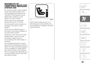 85
85 86
86 87
87 88
88 89
89 90
90 91
91 92
92 93
93 94
94 95
95 96
96 97
97 98
98 99
99 100
100 101
101 102
102 103
103 104
104 105
105 106
106 107
107 108
108 109
109 110
110 111
111 112
112 113
113 114
114 115
115 116
116 117
117 118
118 119
119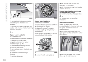 120
120 121
121 122
122 123
123 124
124 125
125 126
126 127
127 128
128 129
129 130
130 131
131 132
132 133
133 134
134 135
135 136
136 137
137 138
138 139
139 140
140 141
141 142
142 143
143 144
144 145
145 146
146 147
147 148
148 149
149 150
150 151
151 152
152 153
153 154
154 155
155 156
156 157
157 158
158 159
159 160
160 161
161 162
162 163
163 164
164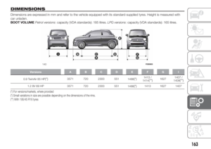 165
165 166
166 167
167 168
168 169
169 170
170 171
171 172
172 173
173 174
174 175
175 176
176 177
177 178
178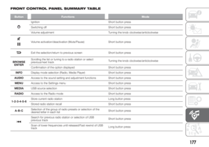 179
179 180
180 181
181 182
182 183
183 184
184 185
185 186
186 187
187 188
188 189
189 190
190 191
191 192
192 193
193 194
194 195
195 196
196 197
197 198
198 199
199 200
200 201
201 202
202 203
203 204
204 205
205 206
206 207
207 208
208 209
209 210
210 211
211 212
212 213
213 214
214 215
215 216
216 217
217 218
218 219
219 220
220 221
221 222
222 223
223 224
224 225
225 226
226 227
227