Page 145 of 196
143
Special features
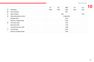
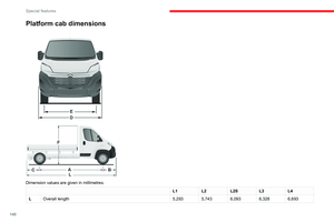
10Double chassis cab/double platform cab dimensions
Dimension values are given in millimetres.
Page 146 of 196
144
Special features
Double chassis cabDouble platform cab
L3 L4L2L3L4
L Overall length 5,8436,2085,7386,2286,678
A Wheelbase 4,0353,4504,035
B Front overhang 948948
C Rear overhang 8601,2251,3401,2451,695
D Width (with/without mirrors) 2,508/2,050-/2,100
- Buildable width --
- Maximum buildable width --
E Front track width 1,8101,810
- Rear track width 1,7901,790
- Increased rear track width 1,9801,980
F Overall height 2,2542,153
- Maximum buildable height --Tipper truck
The lifting of the tipper is provided by a hydro-
electric unit powered by the vehicle's battery.
The ascent or descent is done by holding the
corresponding buttons of the magnetic and
removable remote control located on a support
inside the cab.
Page 147 of 196

145
Special features
10Tipper truck
The lifting of the tipper is provided by a hydro-
electric unit powered by the vehicle's battery.
The ascent or descent is done by holding the
corresponding buttons of the magnetic and
removable remote control located on a support
inside the cab.
The lifting of the tipper is powered by unit's
motor.
The descent is powered by a solenoid valve
opening the strut's oil return.
An anti-drop system makes the descent of the
tipper safe whether static or lifting.
Safety recommendations
Never drive with the tail board down.
Ensure that there are no people or
obstacles present (on the ground and higher
up) when unloading.
Never leave the tipper raised when not in use.
Always tip with the upper part of the rear tail
board locked.
Observe the payload on the tare plate on the
vehicle.
Regularly check that the suspensions are in
good condition and that the tyres are inflated
to the recommended pressure.
Spread the load evenly in the tipper.
Transport homogeneous products which flow
easily.
Never drive, even slowly, with the tipper
raised.
Tip on a flat and hard surface: sloping or loose ground can cause a displacement
of the centre of gravity which affects the stability
of the whole unit.
Page 148 of 196

146
Special features
Specifications
EquipmentDetails
Tipper truck Tipper truck bed consisting of 2 high strength steel blanks, 2.5 mm thickness, zinc-coated, joined by central and
longitudinal laser welding.
Body-coloured tipper truck.
Structure of the tipper truck 2 main sidemembers in galvanised high strength steel.
1 ram-head crossmember made of steel tube.
Galvanised high strength steel crossmembers. Assembly protected against corrosion by the application of a
powder paint coating.
Sub-frame 2 “C”-shaped sidemembers in high strength steel, 2.5 mm thickness, secured internally by widened lower wing.
Mounted on base vehicle with high strength steel stamped brackets.
1 ram-foot crossmember made of steel and mechanically-welded tube, hot-dip galvanised.
1 rear hinge crossmember in galvanised steel.
Support stops on sidemember ends.
Rear lamp protection grille.
Truck side guards and wing supports in galvanised steel.
Boards High strength steel boards, 15/10 thickness, cold-formed and assembled by continuous laser welding.
Anti-corrosion protection guaranteed by a powder coating treatment.
Locking handles with reinforced zinc coating, integrated in the recess of the board.
Ladder-carrier Galvanised steel rails. Panels and crossmembers in lacquered steel with crimped bolts.
Electropump unit 12 Volts/2 kW.
Operating temperature: -20 to +70°C.
Hydraulic ram Expansion, nitride rod, 3 bodies, Diam: 107 mm.
Maximum pressure: 20 bar.
Hydraulic oil ISO HV 46 type mineral or equivalent.
Dimensions
This adaptation is available only on L2 single
cab; refer to the table below for the specifications
of the tipper truck.
Tipper truck (in mm)
Useable length 3,200
Overall length 3,248
Useable width 2,000
Overall width 2,100
Height of boards 350
Weight of the conversion (in
kg) 550
For the L2 chassis cab specifications,
refer to the Dimensions section of the
platform version.
Weights and towed loads
(kg)
The braked trailer weight with load transfer can
be increased, provided that the equivalent of this
load is removed from the vehicle so as not to
exceed the GTW. Warning! Towing using a lightly
loaded vehicle can adversely affect roadholding.
The kerb weight is equal to the unladen weight +
driver (75 kg) + tank full to 90%.
Page 149 of 196

147
Special features
10Dimensions
This adaptation is available only on L2 single
cab; refer to the table below for the specifications
of the tipper truck.
Tipper truck (in mm)
Useable length 3,200
Overall length 3,248
Useable width 2,000
Overall width 2,100
Height of boards 350
Weight of the conversion (in
kg) 550
For the L2 chassis cab specifications,
refer to the Dimensions section of the
platform version.
Weights and towed loads
(kg)
The braked trailer weight with load transfer can
be increased, provided that the equivalent of this
load is removed from the vehicle so as not to
exceed the GTW. Warning! Towing using a lightly
loaded vehicle can adversely affect roadholding.
The kerb weight is equal to the unladen weight +
driver (75 kg) + tank full to 90%.
Before towing a trailer, check that:
– the vertical force exerted on the towball is
not greater than the value (S) indicated on the
trailer’s tare plate;
– the Towed Weight (TW) is less than the value
indicated on the trailer’s tare plate and the Gross Vehicle Weight (GVW) does not exceed the
value indicated on the vehicle’s tare plate.
– in the case of a self-supporting trailer, the
Gross Train Weight (GTW) must not exceed the
value indicated on the vehicle's tare plate.
Hydraulic system
These precautions are mandatory for any
work on the hydraulic system.
– When carrying out maintenance work under
the tipper body, place the tipper body in the
safety position secured with its stay (position
indicated by a red arrow under the back of the
tipper body),
Page 150 of 196

148
Special features
– Never work under a tipper body that is not
supported,
– Switch off the power supply to the electro-
hydraulic unit using the circuit breaker,
– Vehicle stationary, engine off.
For safety reasons, we very strongly
advise against doing anything under the
tipper body while it is being operated or while
it is being serviced.
Maintenance
Reservoir
Regularly check and top up the engine oil level.
Change the oil once a year. If the oil contains
water, change it.
Regularly check the condition of the hose and
ensure the hydraulic system is properly sealed.
Pump and motor
No servicing required. The rolling elements are
permanently lubricated and the bearings are
lubricated by the pumped oil.
Lubrication
The pins of the tipper truck and the ram do not
contain lubricant. Regularly lubricate the hinges
and the grab handles of the side boards as well
as the retaining hooks of the rear board.
Sub-frame and tipper truck
For maximum service life, you are advised to
maintain your tipper truck by regularly washing it
using a power washer.
Carry out any required paint touch-ups quickly to
prevent the spread of rust.
After 8 months of use, check the tightening torque of the connection
between the chassis and the underbody (in
accordance with the manufacturer's
bodybuilding recommendations).
Cleaning the slide valve
► Loosen cap 244A, taking care with the ball
and retrieving it.
► Using a wide screwdriver, unscrew the banjo
bolt/piston assembly.
► Check that the piston slides freely and
remove any foreign bodies. Use a magnet to
remove any metal filings.
► Refit the assembly and make sure that the
piston slides freely. Retain the ball with a little
grease on the cap for refitting.
► Bleed the hydraulic unit.
Bleeding the hydraulic unit
► Unscrew hexagonal cap 257.
► Loosen internal screw 587 by half a turn,
using a 6 mm hex key.
► Operate the unit for a few seconds by
pressing the raise button.
The tipper truck does not rise or rises very
slowly. When the oil exits through this opening,
the unit is bled.
► Retighten screw 587 and replace cap 257.
Check that the tipper truck lowers correctly.
Detailed diagram of the UD2386 hydraulic
unit
Diagnostics
Symptoms ElectricHydraulic Verification/Check
The hydraulic unit does not work. XPower harness and unit relay.
X Control harness (control unit).
X Circuit-breaker.
Very noisy unit, rises slowly. XSuction strainer clogged or crushed at the bottom of the tank.
Very noisy new unit, rises quickly. XPump alignment, change the unit.
The ram lowers by itself. XLowering valve crushed or blocked.
The ram does not lower. XYes, check the slide valve and bleed.
Refer to the "Maintenance" section.
X No, check the coil and the electrical connections of the valve.
X No, replace the solenoid valve.
X No, check the alignment of the ram.
The unit works but its pressure does
not increase. X
Slide valve jammed if no solenoid valve on the unit.
Refer to the "Maintenance" section.
X Pressure relief device, setting, dirt.
X Pump seal out of service.
X Motor/pump coupling.
X Pump loose from its support.
The hydraulic unit does not work. XSolenoid valve blocked, replace it or retighten the nut behind the strainer .
The control unit does not work. XCheck connection and contacts.
Emulsion in the tank. XIncorrectly positioned return pipe.
X Insufficient oil level.
Page 151 of 196

149
Special features
10Diagnostics
SymptomsElectricHydraulic Verification/Check
The hydraulic unit does not work. XPower harness and unit relay.
X Control harness (control unit).
X Circuit-breaker.
Very noisy unit, rises slowly. XSuction strainer clogged or crushed at the bottom of the tank.
Very noisy new unit, rises quickly. XPump alignment, change the unit.
The ram lowers by itself. XLowering valve crushed or blocked.
The ram does not lower. XYes, check the slide valve and bleed.
Refer to the "Maintenance" section.
X No, check the coil and the electrical connections of the valve.
X No, replace the solenoid valve.
X No, check the alignment of the ram.
The unit works but its pressure does
not increase. X
Slide valve jammed if no solenoid valve on the unit.
Refer to the "Maintenance" section.
X Pressure relief device, setting, dirt.
X Pump seal out of service.
X Motor/pump coupling.
X Pump loose from its support.
The hydraulic unit does not work. XSolenoid valve blocked, replace it or retighten the nut behind the strainer .
The control unit does not work. XCheck connection and contacts.
Emulsion in the tank. XIncorrectly positioned return pipe.
X Insufficient oil level.
Page 152 of 196
150
Special features
SymptomsElectricHydraulic Verification/Check
The oil flows back through the oil
breather pipe. X
Oil level too high.
X Tolerance of the oil breather pipe membrane too high, to be replaced.
Valid only for UD2386 units.
The fuse blows while lowering. XReplace the lowering coil.