2020 Alfa Romeo 4C Owner handbook (in English)
-
 1
1 -
 2
2 -
 3
3 -
 4
4 -
 5
5 -
 6
6 -
 7
7 -
 8
8 -
 9
9 -
 10
10 -
 11
11 -
 12
12 -
 13
13 -
 14
14 -
 15
15 -
 16
16 -
 17
17 -
 18
18 -
 19
19 -
 20
20 -
 21
21 -
 22
22 -
 23
23 -
 24
24 -
 25
25 -
 26
26 -
 27
27 -
 28
28 -
 29
29 -
 30
30 -
 31
31 -
 32
32 -
 33
33 -
 34
34 -
 35
35 -
 36
36 -
 37
37 -
 38
38 -
 39
39 -
 40
40 -
 41
41 -
 42
42 -
 43
43 -
 44
44 -
 45
45 -
 46
46 -
 47
47 -
 48
48 -
 49
49 -
 50
50 -
 51
51 -
 52
52 -
 53
53 -
 54
54 -
 55
55 -
 56
56 -
 57
57 -
 58
58 -
 59
59 -
 60
60 -
 61
61 -
 62
62 -
 63
63 -
 64
64 -
 65
65 -
 66
66 -
 67
67 -
 68
68 -
 69
69 -
 70
70 -
 71
71 -
 72
72 -
 73
73 -
 74
74 -
 75
75 -
 76
76 -
 77
77 -
 78
78 -
 79
79 -
 80
80 -
 81
81 -
 82
82 -
 83
83 -
 84
84 -
 85
85 -
 86
86 -
 87
87 -
 88
88 -
 89
89 -
 90
90 -
 91
91 -
 92
92 -
 93
93 -
 94
94 -
 95
95 -
 96
96 -
 97
97 -
 98
98 -
 99
99 -
 100
100 -
 101
101 -
 102
102 -
 103
103 -
 104
104 -
 105
105 -
 106
106 -
 107
107 -
 108
108 -
 109
109 -
 110
110 -
 111
111 -
 112
112 -
 113
113 -
 114
114 -
 115
115 -
 116
116 -
 117
117 -
 118
118 -
 119
119 -
 120
120 -
 121
121 -
 122
122 -
 123
123 -
 124
124 -
 125
125 -
 126
126 -
 127
127 -
 128
128 -
 129
129 -
 130
130 -
 131
131 -
 132
132 -
 133
133 -
 134
134 -
 135
135 -
 136
136 -
 137
137 -
 138
138 -
 139
139 -
 140
140 -
 141
141 -
 142
142 -
 143
143 -
 144
144 -
 145
145 -
 146
146 -
 147
147 -
 148
148 -
 149
149 -
 150
150 -
 151
151 -
 152
152 -
 153
153 -
 154
154 -
 155
155
 23
ELECTRIC WINDOWS
These operate when the ignition key is
turned to MAR and for about three
minutes after the ignition key is turned to
STOP or removed unless one of the doors
is opened.
The buttons")
 KNOWING YOUR CAR
24
BOOT / BONNET
15)
OPENING
IMPORTANT Temperatures higher than
65°C may be reached in the boot during
normal use. Be careful when transporting
objects which may be damaged by
temper")
 25
CLOSING
Procedure
19)
❒ hold the tailgate up with one hand and
use the other to remove rod 2 fig. 23
from housing 4 fig. 24 and reinsert it in
its locking device 3 fig. 23;
❒ lower the tai")
 KNOWING YOUR CAR
26
❒ introducing the hand in the opening
cleared by the flap, find out the pressure-
fit protective cap 2 fig. 26 and remove it;
❒ in the luggage compartment find the
supplied s")
 27
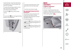
Alfa DNA SYSTEM
(Car dynamic control system)
This device allows, using lever 1 fig. 28
(on the central tunnel), four car response
modes to be selected according to
driving style and road condition")
 KNOWING YOUR CAR
28
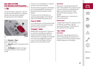
Deactivation
To deactivate “Race” mode and return to
“Dynamic”, move lever 1 fig. 28
downwards (to letter “a”) and keep it in
this position for half a second.
“ALL WE")
 KNOWING THE INSTRUMENT
PANEL TOOLS
ON BOARD PANEL AND INSTRUMENTS ................................................... 29
DISPLAY .....................................................................")
 KNOWING THE INSTRUMENT PANEL TOOLS
30
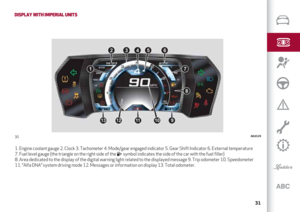
CONTROL PANEL AND ON-BOARD INSTRUMENTS
DISPLAY WITH METRIC UNITS
1. Engine coolant gauge 2. Clock 3. Tachometer 4. Mode/gear engaged indicator 5. Gear Shift Indic")