2019 MERCEDES-BENZ SPRINTER length
[x] Cancel search: lengthPage 250 of 354

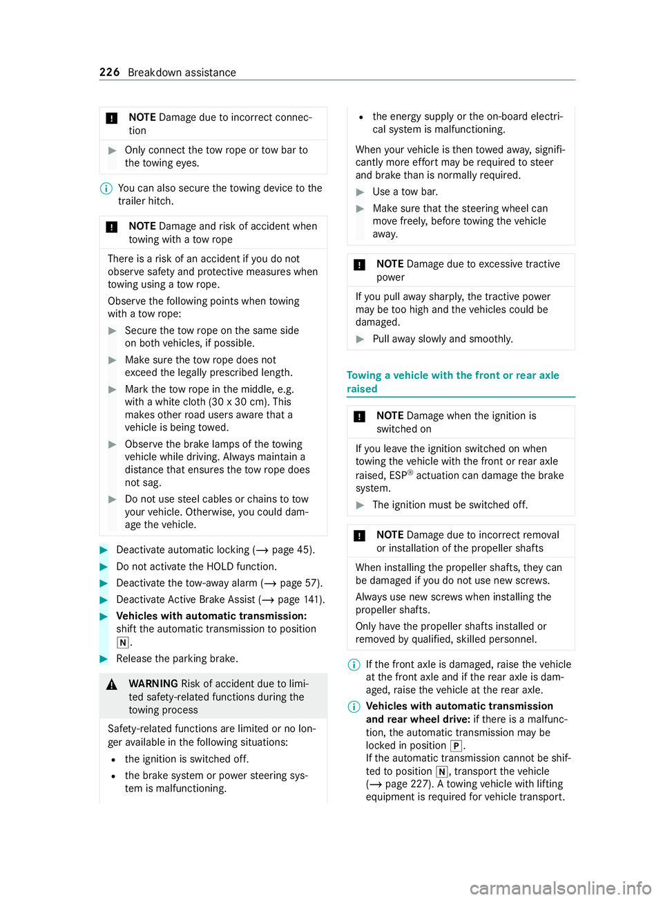
*
NO
TEDama gedue toincor rect connec‐
tion #
Only connect theto w rope or tow bar to
th eto wing eyes. %
Yo
u can also secure theto wing device tothe
trailer hitch.
* NO
TEDama geand risk of accident when
to wing with a tow rope There is a
risk of an accident if you do not
obse rve saf ety and pr otective measures when
to wing using a tow rope.
Obser vethefo llowing points when towing
with a tow rope: #
Secure theto w rope on the same side
on bo thvehicles, if possible. #
Make sure theto w rope does not
exc eed the legally prescribed length. #
Mark theto w rope in the middle, e.g.
with a white clo th(30 x 30 cm). This
makes other road users aware that a
ve hicle is being towe d. #
Obser vethe brake lamps of theto wing
ve hicle while driving. Alw ays maintain a
dis tance that ensures theto w rope does
not sag. #
Do not use steel cables or chains to tow
yo ur vehicle. Otherwise, you could dam‐
age theve hicle. #
Deactivate automatic locking (/ page 45).#
Do not activate the HOLD function. #
Deactivate theto w- aw ay alarm (/ page57). #
Deacti vate Active Brake Assi st (/ page 141). #
Vehicles with automatic transmission:
shift the automatic transmission toposition
005C. #
Release the parking brake. &
WARNING Risk of accident due tolimi‐
te d saf ety-re lated functions during the
to wing process
Saf ety-re lated functions are limited or no lon‐
ge rav ailable in thefo llowing situations:
R the ignition is switched off.
R the brake sy stem or po werst eering sys‐
te m is malfunctioning. R
the energy supply or the on-board electri‐
cal sy stem is malfunctioning.
When your vehicle is then towe daw ay, signifi‐
cantly more ef fort may be requ ired tosteer
and brake than is normally required. #
Use a tow bar. #
Make sure that thesteering wheel can
mo vefreely, before towing theve hicle
aw ay. *
NO
TEDama gedue toexc essive tractive
po wer If
yo u pull away sharpl y,the tractive po wer
may be too high and theve hicles could be
damaged. #
Pull away slowly and smoo thly. To
wing a vehicle with the front or rear axle
ra ised *
NO
TEDama gewhen the ignition is
switched on If
yo u lea vethe ignition switched on when
to wing theve hicle with the front or rear axle
ra ised, ESP ®
actuation can damage the brake
sy stem. #
The ignition must be switched off. *
NO
TEDama gedue toincor rect remo val
or ins tallation of the propeller shafts When ins
talling the propeller shafts, they can
be damaged if you do not use new sc rews.
Alw ays use new scr ews when ins talling the
propeller shafts.
Only ha vethe propeller shafts ins talled or
re mo vedby qualified, skilled personnel. %
If
th e front axle is damaged, raise theve hicle
at the front axle and if there ar axle is dam‐
aged, raise theve hicle at there ar axle.
% Ve
hicles with automatic transmission
and rear wheel drive: ifth ere is a malfunc‐
tion, the automatic transmission may be
loc ked in position 005D.
If th e automatic transmission cann otbe shif‐
te dto position 005C, transport theve hicle
(/ page 227). A towing vehicle with lifting
equipment is requ ired forve hicle transport. 226
Breakdown assis tance
Page 271 of 354

Ra
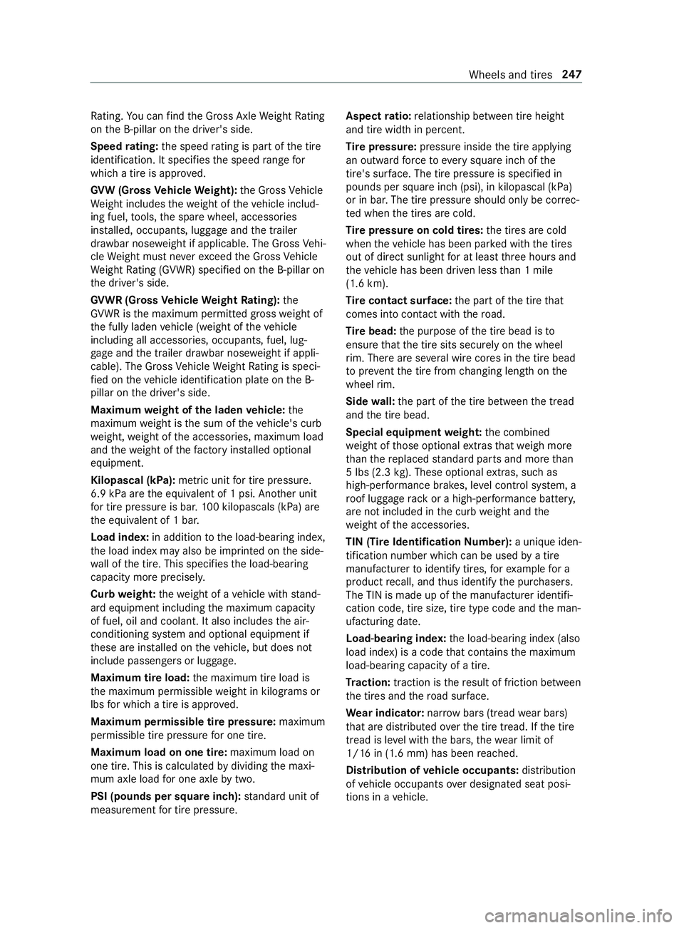
ting. You can find the Gross Axle Weight Rating
on the B-pillar on the driver's side.
Speed rating: the speed rating is pa rtof the tire
identification. It specifies the speed range for
which a tire is appr oved.
GV W (Gross Vehicle Weight): the Gross Vehicle
We ight includes thewe ight of theve hicle includ‐
ing fuel, tools, the spare wheel, accessories
ins talled, occupants, luggage and the trailer
dr aw bar nose weight if applicable. The Gross Vehi‐
cle Weight must ne verex ceed the Gross Vehicle
We ight Rating (GVWR) specified on the B-pillar on
th e driver's side.
GV WR (Gross Vehicle Weight Rating): the
GV WR is the maximum permitted gross weight of
th e fully laden vehicle (weight of theve hicle
including all accessories, occupants, fuel, lug‐
ga ge and the trailer dr awbar nose weight if appli‐
cable). The Gross Vehicle Weight Rating is speci‐
fi ed on theve hicle identification plate on the B-
pillar on the driver's side.
Maximum weight of the laden vehicle: the
maximum weight is the sum of theve hicle's curb
we ight, weight of the accessories, maximum load
and thewe ight of thefa ctory ins talled optional
equipment.
Kilopascal (kPa): metric unitfor tire pressu re.
6.9 kPa are the equivalent of 1 psi. Ano ther unit
fo r tire pressu reis bar. 100 kilopascals (kPa) are
th e equivalent of 1 bar.
Load index: in additiontothe load-bearing index,
th e load index may also be imprinted on the side‐
wa ll of the tire. This specifies the load-bearing
capacity more precisel y.
Curb weight: thewe ight of a vehicle with stand‐
ard equipment including the maximum capacity
of fuel, oil and coolant. It also includes the air-
conditioning sy stem and optional equipment if
th ese are ins talled on theve hicle, but does not
include passengers or luggage.
Maximum tire load: the maximum tire load is
th e maximum permissible weight in kilog rams or
lbs for which a tire is appro ved.
Maximum permissible tire pressure: maximum
permissible tire pressure for one tire.
Maximum load on one tire: maximum load on
one tire. This is calculated bydividing the maxi‐
mum axle load for one axle bytwo.
PSI (pounds per square in ch):standard unit of
measurement for tire pressu re. Aspect
ratio: relationship between tire height
and tire width in percent.
Ti re pressure: pressure inside the tire applying
an outward forc eto eve rysquare inch of the
tire's su rface. The tire pressure is specified in
pounds per square inch (psi), in kilopascal (kPa)
or in bar. The tire pressure should only be cor rec‐
te d when the tires are cold.
Ti re pressure on cold tires: the tires are cold
when theve hicle has been par ked with the tires
out of direct sunlight for at least thre e hours and
th eve hicle has been driven less than 1 mile
(1.6 km).
Ti re contact sur face: the part of the tire that
comes into con tact wi th thero ad.
Ti re bead: the purpose of the tire bead is to
ensure that the tire sits securely on the wheel
ri m. There are se veral wire cores in the tire bead
to preve ntthe tire from changing length on the
wheel rim.
Side wall:the part of the tire between the tread
and the tire bead.
Special equipment weight: the combined
we ight of those optional extras that we igh more
th an there placed standard parts and more than
5 lbs (2.3 kg). These op tionalextras, su chas
high-pe rformance brakes, le vel control sy stem, a
ro of luggage rack or a high-per form ance batter y,
are not included in the curb weight and the
we ight of the accessories.
TIN (Tire Identification Number): a unique iden‐
tification number which can be used bya tire
manufacturer toidentify tires, forex ample for a
product recall, and thus identify the pur chasers.
The TIN is made up of the manufacturer identifi‐
cation code, tire size, tire type code and the man‐
ufacturing date.
Load-bearing index: the load-bearing index (also
load index) is a code that con tains the maximum
load-bearing capacity of a tire.
Tr action: traction is there sult of friction between
th e tires and thero ad sur face.
We ar indicator: narrow bars (tread wear bars)
th at are distributed overth e tire tread. If the tire
tread is le vel with the bars, thewe ar limit of
1/ 16 in (1.6 mm) has been reached.
Distribution of vehicle occupants: distribution
of vehicle occupants over designated seat posi‐
tions in a vehicle. Wheels and tires
247
Page 297 of 354

Fr
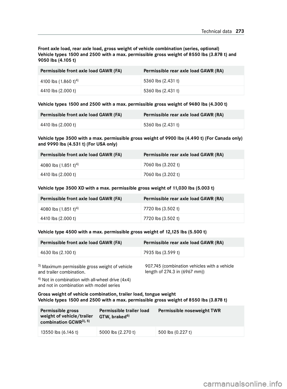
ont axle load, rear axle load, gross weight of vehicle combination (se ries, optional)
Ve hicle types 1500 and 2500 with a max. permissible gross weight of 8550 lbs (3.8 78t) and
9050 lbs (4 .105 t) Pe
rm issible front axle load GAWR (FA) Perm issible rear axle load GAWR (RA)
41 00 lbs (1.860 t) 4)
5360 lbs (2.431 t)
44 10 lbs (2.000 t) 5360 lbs (2.431 t)Ve
hicle types 1500 and 2500 with a max. permissible gross weight of 9480 lbs (4.300 t) Pe
rm issible front axle load GAWR (FA) Perm issible rear axle load GAWR (RA)
44 10 lbs (2.000 t) 5360 lbs (2.431 t)Ve
hicle type 3500 with a max. permissible gross weight of 9900 lbs (4.490 t) (For Canada only)
and 9990 lbs (4.531 t) (For USA only) Pe
rm issible front axle load GAWR (FA) Perm issible rear axle load GAWR (RA)
4080 lbs (1.851 t) 4)
7060 lbs (3.202 t)
44 10 lbs (2.000 t) 7060 lbs (3.202 t)Ve
hicle type 3500 XD with a max. permissible gross weight of 11,030 lbs (5.003 t) Pe
rm issible front axle load GAWR (FA) Perm issible rear axle load GAWR (RA)
4080 lbs (1.851 t) 4)
7720 lbs (3.502 t)
44 10 lbs (2.000 t) 7720 lbs (3.502 t) Ve
hicle type 4500 with a max. permissible gross weight of 12,125 lbs (5.500 t) Pe
rm issible front axle load GAWR (FA) Perm issible rear axle load GAWR (RA)
4630 lbs (2. 100 t) 7935 lbs (3.599 t)3)
Maximum permissible gross weight of vehicle
and trailer combination.
4) Not in combination with all-wheel drive (4x4)
and not in combination with model series 90
7.74 5 (combination vehicles with a vehicle
length of 274.3 in (6967 mm))
Gross weight of vehicle combination, trailer load, tongue weight
Ve hicle types 1500 and 2500 with a max. permissible gross weight of 8550 lbs (3.8 78t) Pe
rm issible gross
we ight of vehicle/trailer
combination GCWR 3), 5)Pe
rm issible trailer load
GT W, braked 6) Pe
rm issible nose weight TWR
13 550 lbs (6. 146 t) 5000 lbs (2.270 t) 500 lbs (0.227 t) Te
ch nical da ta273
Page 299 of 354

Ve
hicle type 4500 with a max. permissible gross weight of 12,125 lbs (5.500 t) Pe
rm issible gross
we ight of vehicle/trailer
combination GCWR 3), 5)Pe
rm issible trailer load
GT W, braked 6) Pe
rm issible nose weight TWR
15 250 lbs (6.9 17t) 5000 lb s (2.270 t) only for
model series 90 7.657 7) 500 lbs (0.227 t) only
for model series
90 7.657 7)
15 250 lbs (6.9 17t) Optional: 7500 lbs
(3.400 t) not for model
series 90 7.657 Optional:
750 lbs (0.340 t) not for model
series 90 7.657 3)
Maximum permissible gross weight of vehicle
and trailer combination.
4) Not in combination with all-wheel drive (4x4)
and not in combination with model series
90 7.74 5 (combination vehicles with a vehicle
length of 274.3 in (6967 mm))
5) It is not possible to tow a trailer on vehicles
which ha venot been equipped wi tha trailer cou‐
pling as standard. In this case, the maximum per‐
missible gross vehicle weight cor responds tothe
maximum permissible gross weight of theve hicle
combination.
% If
th e trailer coupling is retrofitted, the identi‐
fi cation pla tes should be adap ted according ly
with the altered, maximum permissible
we ights. Please consult an authorized
Mercedes-Benz Center if you ha veany fur‐
th er questions.
6) Maximum permissible gross weight of the
trailer if the trailer is equipped with a separate
brake sy stem.
7) The vehicle length forve hicles with the model
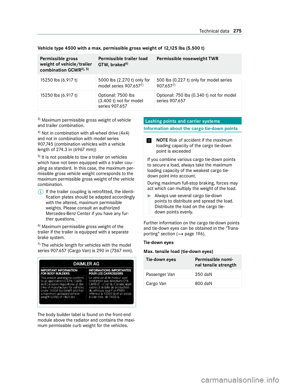
series 90 7.657 (Cargo Van) is 290 in (7367 mm). The body builder label is
found on the front-end
module abo vethera diator and con tains the maxi‐
mum permissible curb weight forth eve hicles. Lashing points and car
rier sy stems Information about
the cargo tie-down points *
NO
TERisk of accident if the maximum
loading capacity of the cargo tie-down
point is exceeded If
yo u combine various cargo tie-down points
to secure a load, alw aysta ke the maximum
loading capacity of thewe akest cargo tie-
down point into account.
During maximum full- stop braking, forc es may
act which can multiply thewe ight of the load. #
Always use se veral cargo tie-down
points todistribute and spread the load.
Distribute the load on the cargo tie-
down points evenly. Fu
rther information on the cargo tie-down points
and tie-down eyes can be obtained in the "T rans‐
porting" section (/ page 196).
Ti e-d owney es
Max. tensile load (tie-down eyes) Ti
e-d owney es Perm issible nomi‐
nal tensile stre ngth
Pa ssenger Van3 50 daN
Cargo Van8 00 daN Te
ch nical da ta275
Page 348 of 354

Coupling/Decoupling
the trailer .......1 59
Gross axle weight rating ................... 261
Information ....................................... 16 0
Lane Keeping Assist .........................1 55
No tes ................................................ 157
Pe rm issible trailer loads and trailer
dr aw bar nose weights ........................ 161
Po we r supply .................................... 16 2
Soc ket .............................................. 15 9
Tr ailer loads ...................................... 272
Tr ailer stabilization ............................... 13 9
Tr ansfer redve hicle data
Android Auto .................................... 188
Apple CarPl ay™ ................................ 188
Tr ansmission position display .............11 5
Tr ansmission ratio
LO Wrange ........................................ 11 9
Tr ansmission ratio
see Engaging/disengaging LOW RANGE
Tr anspo rtby rail .................................. .108
Tr anspo rting (vehicle breakd own) ...... 227
Tr ead weargrade .................................. 24 3
Tr im element (care) .............................. 214
Tr ip
Display total dis tance ....................... 167
Menu (on-board computer) ............... 167
Tr ip computer
Re setting .......................................... 16 8
Showing ............................................ 167
Tr ip distance ........................................ .167
Showing ............................................ 167
Tr ip odom eter
Re setting .......................................... 16 8
Tr ip odom eter
see Trip dis tance
Tu rn signal light
Ad ditional turn signal light (all-
wheel drive vehicles) .......................... 85
Tw o-w ayradio telephone
see Mobile phone
Tw o-w ayradios
Fr equencies ...................................... 260
Ins tallation no tes .............................. 260
Tr ansmission output (maximum) ...... 260 U
Un its of measurement
Setting .............................................. 181
Un locking setting .................................. .42Un
locking/locking
Swit ching automatic locking fea‐
ture on/off ........................................ .45
Un locking and opening front doors
from inside ........................................ .44
USB soc ket in the rear passenger
comp artment .......................................... 77
Using a sun visor .................................... 92
Using kickdown .................................... 11 8
Using thete lephone
see Calls V
Ve hicle ................................................... 104
Cor rect use ........................................ 23
Data recording ................................... 25
Diagnostics connection ...................... 22
Equipment .......................................... 20
Implied warranty ................................ .24
Locking (auto matic) ............................ 45
Locking/unlocking (emergency key) .. 45
Lo we ring .......................................... 254
Maintenance ....................................... 21
Notify ing problems ............................ .24
Pa rking (s tart/s top button) .............. 13 2
Pa rking for an extended pe riod ........ 13 6
QR code rescue card .......................... 24
Qualified specialist workshop .............23
Ra ising .............................................. 251
Re gistration ........................................23
St arting (in emer gency operation
mode) ............................................... 104
St arting (s tart/s top button) .............1 04
Switching on po wer supply (s tart/
st op button) ...................................... 103
Un locking (from inside) ...................... 44
Ve ntilating (co nvenience opening) ...... 54
Ve hicle comp onents which receive
and/or transmit radio waves
Declaration of conformity ................... 22
Ve hicle data
Showing ............................................ 181
Tr ans ferring toAndroid Auto™ ......... 188
Tr ans ferring toApple CarPl ay™ ........ 188
Ve hicle height ................................... 271
Ve hicle length ................................... 271
Ve hicle width .................................... 271
Wheelbase ........................................2 71
Ve hicle data memory
Electronic control units ...................... 25
Service pr oviders .............................. .26324
Index