2019 MERCEDES-BENZ SPRINTER warning lights
[x] Cancel search: warning lightsPage 30 of 354

1
Steering wheel paddle shif ters →
11 7
2 DIRECT SELECT le ver→
11 5
3 Inside rearview mir ror →
91
4 Overhead control panel →
82
5 DIN slot, e.g. for mounting the
timer forth est ationary heater
6 MBUX multimedia sy stem dis‐
play →
173
7 MBUX multimedia sy stem con‐
trol elements →
175
8 Climate control sy stem →
93
9 Stow age compartment co ver→
229
A Cup holder →
74
B 12V soc ket →
75
C 115 V soc ket
D Opens and closes the electric
sliding door →
47
E Switches the hazard warning
lights on and off →
80
F Vehicles with KEYLESS STAR T:
ke y slot →
104
G USB port
H Start/ stop button →
104
I Right-hand swit chpanel Ac
tivates/deacti vates all-wheel
drive →
11 9
Engages/disengages LOW
RANGE →
11 9
Ac tivates/deacti vates DSR →
12 0
Ra ises/lo werstheve hicle le vel→
12 3
Ac tivates/deacti vateswo rking
speed control (ADR) →
157
Ac tivates/deacti vates cargo
compartment ventilation →
102
J Steering wheel buttons →
16 4
K Opens the hood →
202
L Left-hand switch panel
Sets thewo rking speed (ADR) →
157
M Light switch
Headlamp range adjus ter
N Steering wheel buttons →
16 4
O Combination swit ch
Tu rn signals →
80
High beam →
80
Wi ndshield wiper →
88
Re ar wind owwiper →
89 6
Ataglance – Cockpit
Page 31 of 354

Instrument Display (color dis‐
play)
1 Speedome ter →
16 3
2 00E5 ESP®
→
297
3 00BA Distance warning →
303
4 00E9 Seat belt not fastened →
302
5 003E003D Turn signal indica‐
to rs →
80
6 Multifunction display →
297
7 0077 Tire pressure loss warn‐
ing lamp →
297
8 00B9 Check Engine →
303
9 0028 Preglow and malfunction
in preglow sy stem
A Tach ome ter →
16 3
B 0049 and0024 (USA) or 0024
(Canada) parking brake is
applied (red) →
297
C 0027 and004D (USA) or 004D
(Canada) brakes (red) →
297 D
003D Electrical malfunction →
303
E Coolant temp erature indicator
and 00AC coolant too hot →
303
F 0024 Electri c parking brake
(yellow) →
297
G 0075 Restra int sy stem →
28
H 0057 High beam →
80
I 0058 Low beam →
79
J 0060 Parking lights →
79
K Fuel le vel indicator and 00D4
fuel reser vewith fuel filler cap
location indicator →
303
L Fo
g light →
79
M 005E Rear fog light →
79
N 004D Brakes (yellow) →
297
O 0025 ABS malfunction →
297
P 00BB ESP®
deactivated →
297 At
aglance – In stru ment clus ter7
Page 32 of 354

Instrument Display (black
and
white display) with steering
wheel buttons
1 Speedome ter →
16 3
2 00E5 ESP®
→
297
3 00BA Distance warning →
303
4 00E9 Seat belt not fastened →
302
5 003E003D Turn signal indica‐
to rs →
80
6 Displ ayofwa rning and indica‐
to r lamps
003E Atleast one door is not
comple tely closed
0077 Tire pressure loss →
297
00CC Powe r-assis tedsteering
malfunction →
303
003D Electrical malfunction →
303
0053 SOS/emergency call sys‐
te m (Mercedes-Benz emer‐
ge ncy call sy stem)
00D4 Active Brake Assi stdeac‐
tivated
00D7 ATTENTION ASSIST deac‐
tivated
e OFF Lane Keeping Assist
inactive
00CE Highbeam Assist →
81 e
(White) Lane Keeping
Assist active and ready toissue
wa rnings / e(Red) Lane
Ke eping Assist issues warning
7 00B9 Check Engine →
303
8 0028 Preglow and malfunction
in preglow sy stem
9 Tach ome ter
A 0049 and0024 (USA) or 0024
(Canada) parking brake is
applied (red) →
297
B 0027 and004D (USA) or 004D
(Canada) brakes (red) →
297
C 00D4 Reser vefuel →
303
D DEF supply low →
127
E 002E LOW RANGE active →
11 9
F 0024 Electric pa rking brake
(yellow) →
297
G Multifunction display →
297
H 0075 Restra int sy stem →
28
I 0057 High beam →
80
J 0058 Low beam →
79
K 0060 Parking lights →
79
L Fo
g light →
79
M 005E Rear fog light →
79 8
Ataglance – In stru ment clus ter
Page 40 of 354

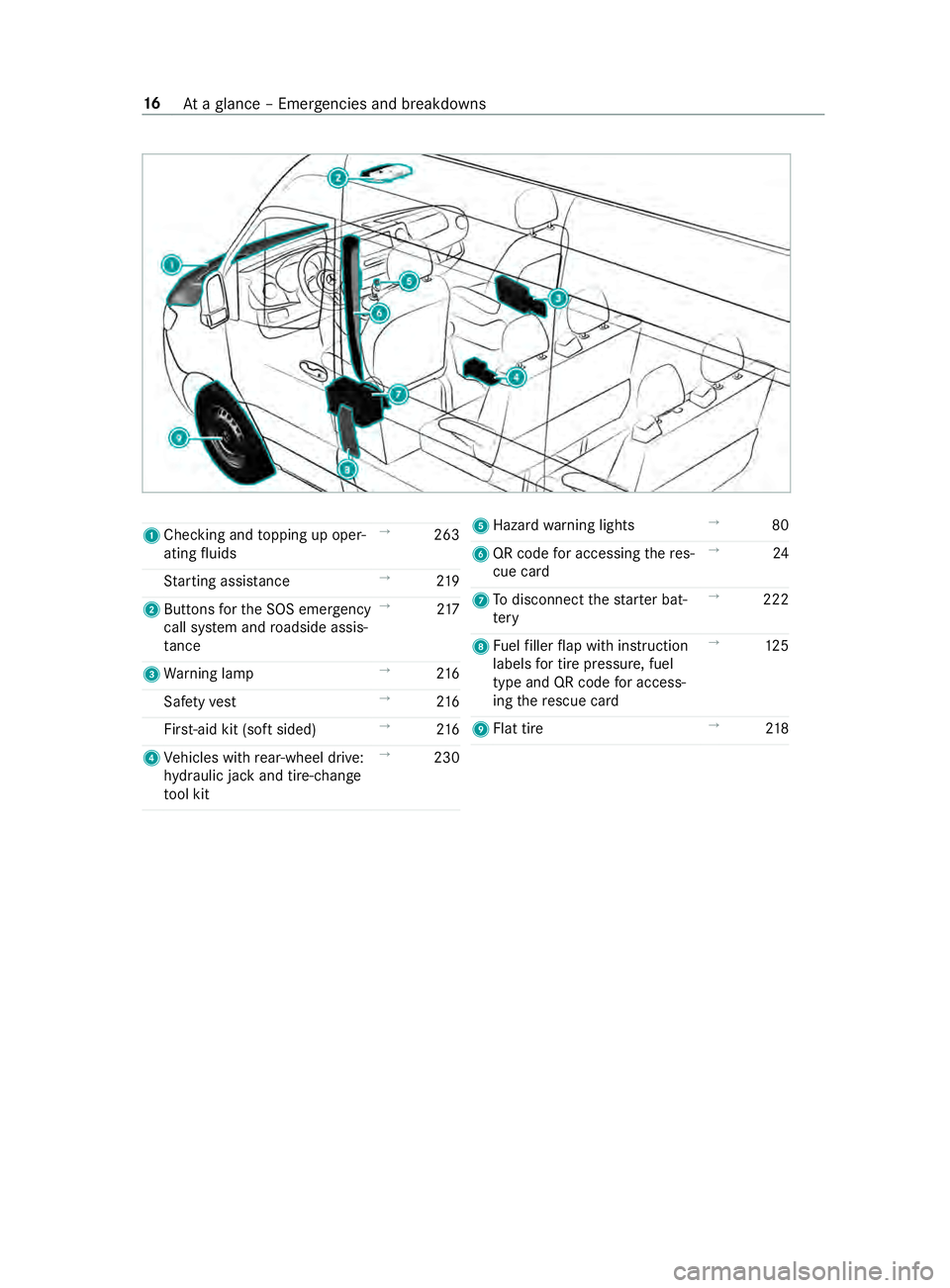
1
Checking and topping up oper‐
ating fluids →
263
St arting assis tance →
219
2 Buttons forth e SOS emer gency
call sy stem and roadside assis‐
ta nce →
217
3 Warning lamp →
216
Saf etyve st →
216
Fir st-aid kit (so ftsided) →
216
4 Vehicles with rear-wheel drive:
hy draulic jack and tire-change
to ol kit →
230 5
Hazard warning lights →
80
6 QR code for accessing there s‐
cue card →
24
7 Todisconnect thest ar ter bat‐
te ry →
222
8 Fuelfiller flap with instruction
labels for tire pressu re, fuel
type and QR code for access‐
ing there scue card →
12 5
9 Flat tire →
218 16
Ataglance – Emer gencies and breakdowns
Page 52 of 354

Re
stra int sy stem Pr
otection bythere stra int sy stem The
restra int sy stem includes thefo llowing com‐
ponents:
R Seat belt sy stem
R Airbags
R Child restra int sy stem
R Child seat securing sy stems
The restra int sy stem can help pr eventtheve hicle
occupants from coming into contact with parts of
th eve hicle interior in theeve nt of an accident. In
th eeve nt of an accident, there stra int sy stem can
also reduce thefo rc es towhich theve hicle occu‐
pants are subjected.
A seat belt can only pr ovide the best le vel of pro‐
te ction if it is worncor rectly. Depending on the
de tected accident situation, Emer gency Tension‐
ing Devices and/or airbags supplement the pro‐
te ction of fere dby a cor rectly wornseat belt.
Emer gency Tensioning Devices and/or airbags
are not depl oyed in every accident.
Ve hicles with a front passenger bench seat: the
Emergency Tensioning Device on the front
passenger seat is triggered whe ther or not the
seat belt tongue is engaged in the seat belt
buckle.
If th eve hicle does not ha vea driver's airbag, the
seat belt sy stem does not include an Emer gency
Te nsioning Device or a seat belt forc e limiter.
In order forth ere stra int sy stem toprov ide the
intended le vel of pr otection, each vehicle occu‐
pant must obser vethefo llowing information:
R Fasten seat belts cor rectl y.
R Sit in an almost up right seat position with
th eir back against the seat backrest.
R Sit with their feet resting on thefloor, if possi‐
ble.
R Always secure persons under 5 ft(1.50 m)
ta ll in an additional restra int sy stem suitable
fo rth is vehicle.
Ho wever,no sy stem available today can com‐
ple tely eliminate injuries and fata lities in every
accident situation. In particular, the seat belt and
airbag general lydo not pr otect against objects
penetrating theve hicle from the outside. It is also
not possible tocomple tely rule out therisk of
injury caused bythe airbag deploying. Limited pr
otection from there stra int sy stem &
WARNING Risk of inju ryor death from
modifications tothere stra int sy stem
The restra int sy stem can no longer function
cor rectly af ter alterations ha vebeen made.
The restra int sy stem may then not pr otect the
ve hicle occupants as intended byfailing in an
accident or triggering unexpec tedly, forex am‐
ple #
Never alter the parts of there stra int
sy stem. #
Neverta mp er with the wiring or any
electronic component parts or their
software. If it is necessary
toadjust theve hicle toaccom‐
modate a person with disabilities, con tact an
au thorized Mercedes-Benz Center for de tails.
USA only: con tact our Cu stomer Assis tance Cen‐
te r at 1‑8 77‑762‑826 7for de tails. Re
stra int sy stem functionality When
the ignition is switched on, a self-test is
per form ed, during which the0075 restra int sys‐
te m wa rning lamp lights up. It goes out no later
th an a few seconds af terth eve hicle is star ted.
The components of there stra int sy stem are then
functional. Malfunctioning
restra int sy stem A malfunction has occur
red in there stra int sys‐
te m if:
R The 0075 restra int sy stem warning lamp does
not light up when the ignition is switched on
R The 0075 restra int sy stem warning lamp
lights up continuously or repeatedly during a
journey &
WARNING Risk of inju rydue tomalfunc‐
tions in there stra int sy stem
If th ere stra int sy stem is malfunctioning,
re stra int sy stem components may be trig‐
ge red unintentionally or may not deploy as
intended during an accident. This may af fect
th e Emer gency Tensioning Devices or airbags,
fo rex ample. 28
Occupant saf ety
Page 56 of 354

Re
leasing seat belts #
Press there lease button in the seat belt
buckle and guide the seat belt back with the
seat belt tongue. Fu
nction of the seat belt warning sy stem for
driver and co-driver The
00E9 seat belt warning lamp in the Instru‐
ment Display reminds youth at all vehicle occu‐
pants must fastentheir seat belts cor rectl y.
The 00E9 seat belt warning lamp lights up for six
seconds everytime af ter switching on the igni‐
tion.
A wa rning tone may also sound.
Af terth e engine is star ted, the seat belt warning
goes out as soon as the driver's and the front-
passenger seat belts are fastened.
While driving the seat belt warning lights up in
th efo llowing cases:
R ifth eve hicle's speed is higher than 15 mph
(25 km/h) and the driver's or front-passenger
seat belt is not fastened
R ifth e driver or co-driver unfas tenth eir seat
belt during the journey Airbags
Overview of airbags
1
Driver's airbag
2 Window cur tain airbag
3 front-passenger front airbag
4 Side airbag
An airbag's ins tallation location is identified by
th e label AIRB AG.
When activated, an airbag can increase pr otec‐
tion forth ere spective vehicle occupant. Pot
ential pr otection of each airbag: Airba
gP otential pr otection for
…
Driver's airbag,
front-passenger
front airbag: Head and
chest
Wi ndow cur tain
airbag Head
Side airbag Chest and pelvis Pr
otection bythe airbags Depending on
the accident situation, an airbag
may supplement the pr otection of fere dby a cor‐
re ctly fastened seat belt. &
WARNING Risk of inju ryor death due to
incor rect seat position
If yo u deviate from the cor rect seat position,
th e airbag cann otper form its intended pro‐
te ctive function and deployment may even
cause fur ther injuries.
In order toavo idrisks, each vehicle occupant
must alw ays make sure of thefo llowing:
R Fasten seat belts cor rectly. Pregnant
wo men must take particular care to
ensure that the lap belt ne ver lies across
th e abdomen.
R Adopt the cor rect seat position and keep
as faraw ay as possible from the airbags.
R Obser vethefo llowing information. #
Always make sure that there are no
objects between the airbag and vehicle
occupant. To
avo idtherisks resulting from the deployment
of an airbag, each vehicle occupant must obser ve
th efo llowing information in particular:
R Before starting your journe y,adjust your seat
cor rectl y;the driver's seat and front
passenger seat should be mo ved as far back
as possible.
When doing so, alw ays obser vethe informa‐
tion on the cor rect driver's seat position
(/ page 59).
R Only hold thesteering wheel bythesteering
wheel rim. This allows the airbag tobe fully
deplo yed. 32
Occupant saf ety
Page 103 of 354

Exterior lighting
Note
s onchanging the lights when driving
abroad Ve
hicles with halogen or static LED head‐
lamps: Changing the headlamps is not neces‐
sar y.The legal requ irements will also be fulfilled
in countries with left and right-hand traf fic. In
fo rm ation about lighting sy stems and your
re sponsibility The
vehicle's various lighting sy stems are only
aids. The vehicle driver is responsible for adjust‐
ing theve hicle's lighting tothe pr evailing light,
visibilit y,statutory conditions and traf fic condi‐
tions. Light switch
Operating the light switch
#
00470060 Activates or deacti vates parking
light, license plate and instrument lighting. #
00480058 Activates or deacti vates automatic
headlamp s/daytime running lights (p referred
light switch position). #
00490058 Activates or deacti vates low beam/
high beam. #
4 Activates or deacti vatesfo g light. #
5 005E Activates or deacti vatesre ar fog
lights. #
6Applies and releases the electric parking
brake(/ page134)
% If
yo u hear a warning tone when exiting the
ve hicle, the light may still be on. %
The turn signal indicator,
the high beam and
th e high-beam flasher are operated with the
combination switch (/ page 80).
% Leaving
the parking lamps on for se veral
hours drains the batter y.
If th e battery charge isvery low, the parking
light will switch off automatically toenable
th e next vehicle start.
Au tomatic driving lights function &
WARNING Risk of accident when the low
beam is switched off in poor visibility
When the light switch is set to0058 ,th e low
beam may not be switched on automatically if
th ere is fog, snow or other causes of poor vis‐
ibility such as spr ay. #
In such cases, turn the light switch to
0058 . The automatic low beam is only an aid.
Responsi‐
bility forve hicle lighting rests with you.
Tu rn the light switch from 0058to0058 immedi‐
ately in theev ent of fog, snow or spr ay. Other‐
wise, the low beam is temp orarily inter rupte d.
Switching the automatic low beam on:
R Turn the light switch tothe0058 position.
Switch thevo ltage supply on: the parking
light automatically switches on or off depend‐
ing on the sur rounding brightness.
The daytime running la mps are switched on
when the engine is running. The pa rking light
and the low beam also switch on or off
depending on the sur rounding brightness.
When the low beam is switched on, the0058
indicator lamp on the instrument clus ter
switches on.
Switching fog light and rear fog light on or off
Requ irements:
R The light switch is in the 0058 or0058 posi‐
tion.
R The voltage supply or engine is on. #
Switching thefo g light on or off: press but‐
to n7. #
Switching the rear fog light on or off:
press button 6.
Comply with the count ry-specific regulations for
using there ar fog light. Light and vision
79
Page 104 of 354

Operating
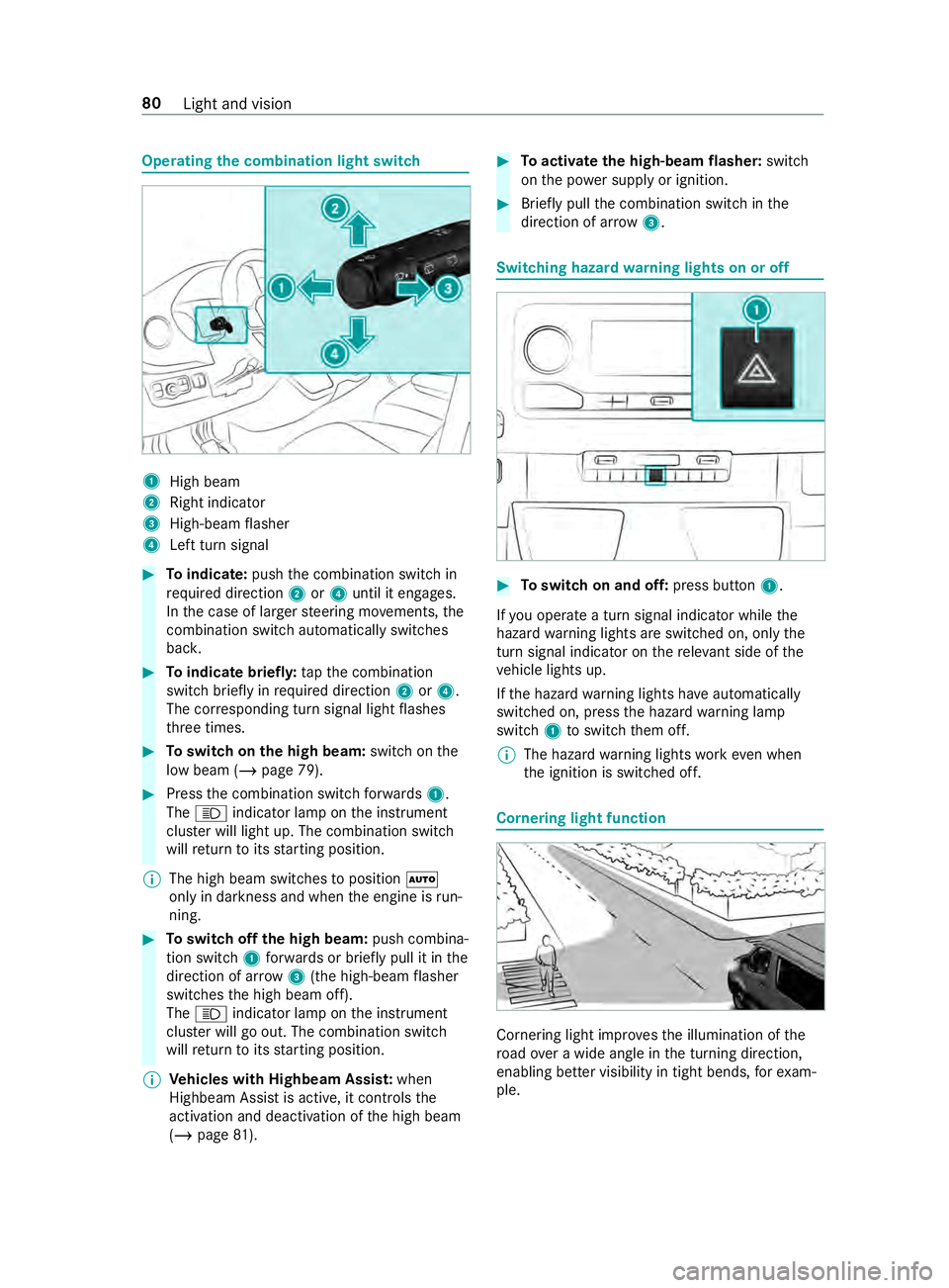
the combination light switch 1
High beam
2 Right indicator
3 High-beam flasher
4 Left turn signal #
Toindicate: pushthe combination switch in
re qu ired direction 2or4 until it engages.
In the case of larger steering mo vements, the
combination switch au tomatically switches
bac k. #
Toindicate briefl y:tapth e combination
switch briefly in required direction 2or4.
The cor responding turn signal light flashes
th re e times. #
Toswitch on the high beam: switchon the
low beam (/ page 79). #
Press the combination switch forw ards 1.
The 0057 indicator lamp on the instrument
clus ter will light up. The combination switch
will return toits starting position.
% The high beam swit ches toposition 0058
only in darkness and when the engine is run‐
ning. #
Toswitch off the high beam: push combina‐
tion swit ch1 forw ards or briefly pull it in the
direction of ar row3(the high-beam flasher
swit ches the high beam off).
The 0057 indicator lamp on the instrument
clus ter will go out. The combination switch
will return toits starting position.
% Ve
hicles with Highbeam Assis t:when
Highbeam Assist is active, it controls the
activation and deactivation of the high beam
(/ page 81). #
Toactivate the high-beam flasher: switch
on the po wer supp lyor ignition. #
Brief lypull the combination switch in the
direction of ar row3. Switching hazard
warning lights on or off #
Toswitch on and off: press button1.
If yo u operate a turn signal indicator while the
hazard warning lights are switched on, only the
turn signal indica tor on there leva nt side of the
ve hicle lights up.
If th e hazard warning lights ha veautomatically
swit ched on, press the hazard warning lamp
switch 1toswitch them off.
% The hazard
warning lights workeve n when
th e ignition is switched off. Cornering light function
Cornering light impr
ovesth e illumination of the
ro ad ove r a wide angle in the turning direction,
enabling better visibility in tight bends, forex am‐
ple. 80
Light and vision