2019 MERCEDES-BENZ SPRINTER length
[x] Cancel search: lengthPage 62 of 354
To
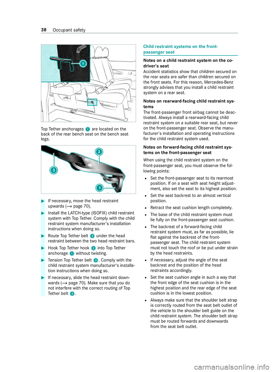
pTe ther anchorages 1are located on the
back of there ar ben chseat on the bench seat
legs. #
If necessar y,mo vethe head restra int
upwards (/ page 70). #
Installth eLA TC H-type (ISOFIX) child restra int
sy stem with TopTe ther. Comply with thech ild
re stra int sy stem manufacturer's ins tallation
instructions when doing so. #
Route TopTe ther belt 3under the head
re stra int between the two head restra int bars. #
Hook TopTe ther hook 2into TopTe ther
anchorage 1without twisting. #
Tension TopTe ther belt 3. Comply with the
ch ild restra int sy stem manufacturer's ins talla‐
tion instructions when doing so. #
If necessar y,slide the head restra int down‐
wa rds (/ page 70). Make sure that you do
not inter fere with the cor rect routing of To p
Te ther belt 3. Child
restra int sy stems on the front-
passenger seat Note
s on a child restra int sy stem on the co-
driver's seat
Ac cident statistics show that children secured on
th ere ar seats are safer than children secured on
th e front seats. Forth is reason, Mercedes-Benz
stro ngly advises that you ins tall a child restra int
sy stem on a rear seat.
Note s onrear wa rd-facing child restra int sys‐
te ms
The front-passen ger front airbag cannot be deac‐
tivated. Alw ays ins tall a rear wa rd-facing child
re stra int sy stem on a suitable rear seat, but ne ver
on the front-passen ger seat. Obser vethe manu‐
fa cturer's ins tallation and operating instructions
fo rth ech ild restra int sy stem used.
Note s onforw ard-facing child restra int sys‐
te ms on the front-passenger seat
When using thech ild restra int sy stem on the
front-passenger seat, you must obse rveth efo l‐
lowing points:
R Set the front-passen ger seat toits rearmost
position. If on a seat with seat height adjust‐
ment, also set the seat toits highest position.
R Set the seat backrest toan almost vertical
position.
R Retract the seat cushion length comple tely.
R The base of thech ild restra int sy stem must
lie fully on the front-passen ger seat cushion.
R The backrest of a forw ard-facing child
re stra int sy stem must, as far as possible, lie
fl at against the backrest of the front-
passenger seat. The child restra int sy stem
must not touch thero of or be put under stra in
by the head restra ints.
R If necessar y,adjust the angle of the seat
backrest and the position of the head
re stra ints acco rding ly.
R Set the seat cushion angle in such a wayth at
th e front edge of the seat cushion is in the
highest position and there ar edge of the seat
cushion is in the lo west position.
R Always make sure that the shoulder belt strap
is cor rectly routed from the seat belt outlet of
th eve hicle tothe shoulder belt guide on the
ch ild restra int sy stem. The shoulder belt strap
must be routed forw ards and down wards
from the seat belt outlet. 38
Occupant saf ety
Page 86 of 354
th
e shoulder section of your seat belt is
ro uted across the center of your shoul‐
der. *
NO
TEDama getothe seats when moving
th e seats back The seats may be damaged
byobjects when
moving the seats bac k. #
When moving the seats bac k,make sure
th at there are no objects in thefo ot we ll,
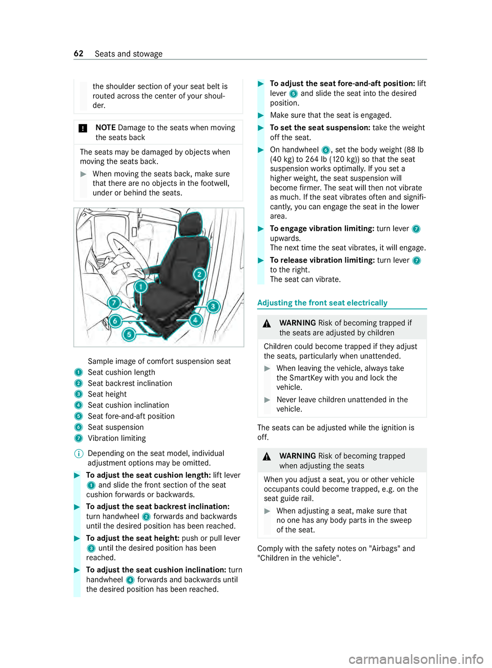
under or behind the seats. Sample image of comfort suspension seat
1 Seat cushion length
2 Seat backrest inclination
3 Seat height
4 Seat cushion inclination
5 Seat fore -and-aft position
6 Seat suspension
7 Vibration limiting
% Depending on
the seat model, individual
adjustment options may be omitted. #
Toadjust the seat cushion length: lift lever
1 and slide the front section of the seat
cushion forw ards or backwards. #
Toadjust the seat backrest inclination:
turn handwheel 2forw ards and backwards
until the desired position has been reached. #
Toadjust the seat heigh t:push or pull le ver
3 until the desired position has been
re ached. #
Toadjust the seat cushion inclination: turn
handwheel 4forw ards and backwards until
th e desired position has been reached. #
Toadjust the seat fore -and-aft position: lift
le ve r5 and slide the seat into the desired
position. #
Make sure that the seat is engaged. #
Toset the seat suspension: take thewe ight
off the seat. #
On handwheel 6, setthe body weight (88 lb
(40 kg)to 264 lb (120 kg)) so that the seat
suspension works optimall y.Ifyo u set a
higher weight, the seat suspension will
become firm er. The seat will then not vibrate
as much. If the seat vibrates of ten and signifi‐
cantly, you can engage the seat in the lo wer
area. #
Toengage vibration limiting: turn lever7
upwards.
The next time the seat vibrates, it will engage. #
Torelease vibration limiting: turn lever7
to theright.
The seat can vibrate. Ad
justing the front seat electrically &
WARNING Risk of becoming trapped if
th e seats are adjus tedby children
Children could become trapped if they adjust
th e seats, particularly when unattended. #
When leaving theve hicle, alw aysta ke
th e SmartK eywith you and lock the
ve hicle. #
Never lea vechildren unat tended in the
ve hicle. The seats can be adjus
ted while the ignition is
off. &
WARNING Risk of becoming trapped
when adjusting the seats
When you adjust a seat, you or other vehicle
occupants could become trapped, e.g. on the
seat guide rail. #
When adjusting a seat, make sure that
no one has any body parts in the sweep
of the seat. Comply with
the saf ety no tes on "Airbags" and
"Children in theve hicle". 62
Seats and stowage
Page 113 of 354

Switching
there ar window wiper on/off 1
00E2 Single wipe/wash
2 00C5 Intermittent wiping #
Single wipe: press button1tothe point of
re sis tance. #
Wiping with washer fluid: press button 1
be yond the point of resis tan ce. #
Toswitch intermittent wiping on or off:
press button 2.
If th ere ar wind owwiper is swit ched on, the
00C5 symbol will appear on the Instrument
Displa y. Re
placing the windshield wiper blades &
WARNING Risk of becoming trapped if
th e windshield wipers are switched on
while wiper blades are being replaced
If th e windshield wipers begin tomo vewhile
yo u are changing the wiper blades, you can
be trapped bythe wiper arm. #
Always switch off the windshield wipers
and the ignition before changing the
wiper blades. &
WARNING Risk of inju ryfrom using the
windshield wipers while the engine hood
is open
When the engine hood is open and the wind‐
shield wipers are set in motion, you can be
trapped bythe wiper linkage. #
Always switch off the windshield wipers
and ignition before opening the engine
hood. %
If
th e wiper blades are wornout, they will not
wipe the windshield proper ly.Re place the
wiper blades twice a year, preferably in
spring and fall. #
Fold wiper arm 3away from the windshield. #
Hold wiper arm 3and turn the wiper blade
aw ay from wiper arm 3inthe direction of
th e ar row asfar as it will go. #
Slide catch 2upwards in the direction of the
ar row until it engages. #
Fold back the wiper blade onto the wiper arm. #
Remo vewiper blade 1from wiper arm. #
Insert new washer blade 1inthe holder on
wiper arm 3.
When doing so, take into account the dif fere nt
lengths of the wiper blades:
R Driver's side: long wiper blade
R Front-passenger side: short wiper blade #
Slide catch 2down wards until it engages. #
Fold wiper arm 3back onto the windshield. Re
placing the windshield wiper blades (WET
WIPER SYSTEM) &
WARNING Risk of becoming trapped if
th e windshield wipers are switched on
while wiper blades are being replaced
If th e windshield wipers begin tomo vewhile
yo u are changing the wiper blades, you can
be trapped bythe wiper arm. #
Always switch off the windshield wipers
and the ignition before changing the
wiper blades. Light and vision
89
Page 114 of 354

&
WARNING Risk of inju ryfrom using the
windshield wipers while the engine hood
is open
When the engine hood is open and the wind‐
shield wipers are set in motion, you can be
trapped bythe wiper linkage. #
Always switch off the windshield wipers
and ignition before opening the engine
hood. %
If
th e wiper blades are wornout, they will not
wipe the windshield proper ly.Re place the
wiper blades twice a year, preferably in
spring and fall. #
Fold wiper arm 3away from the windshield. #
Hold wiper arm 3and turn the wiper blade
aw ay from wiper arm 3inthe direction of
th e ar row asfar as it will go. #
Slide catch 2upwards in the direction of the
ar row until it engages. #
Remo vewiper blade 1from the wiper arm in
th e direction of ar row4. #
Carefully remo vehose 5from the wiper
blade. #
Attach hose 5tothe new wiper blade. #
Insert new washer blade 1inthe holder on
wiper arm 3.
When doing so, take into account the dif fere nt
lengths of the wiper blades:
R Driver's side: long wiper blade
R front-passenger side: short wiper blade #
Slide catch 2down wards until it engages. #
Fold back the wiper blade onto the wiper arm. #
Fold wiper arm 3back onto the windshield. Re
placing the rear window wiper blade #
Fold wiper arm 3away from there ar win‐
do w. #
Press bo thretaining clips 2inthe direction
of the ar row and swivel the wiper blade away
from the wiper arm. #
Pull wiper blade 1upwards out of the holder
on wiper arm 3. #
Insert new washer blade 1inthe holder on
wiper arm 3. #
Push new wiper blade 1onto wiper arm 3
until there taining clips engage. #
Fold wiper arm 3back onto there ar win‐
do w. Mir
rors Operating
the outside mir rors &
WARNING Risk of inju ryfrom adju sting
th eve hicle settings while theve hicle is in
motion
Yo u could lose control of theve hicle in the
fo llowing situations:
R ifyo u adjust the driver's seat, the head
re stra int, thesteering wheel or the mir ror
while theve hicle is in motion
R ifyo ufast enyour seat belt while theve hi‐
cle is in motion #
Before starting the engine: adjust the
driver's seat, the head restra int, the 90
Light and vision
Page 175 of 354
The image from
the 360° Camera appears auto‐
matically in the multimedia sy stem when thefo l‐
lowing conditions are fulfilled:
R The ignition is switched on.
R The rear-end doors are opened.
This means that the area behind theve hicle can
be monitored.
When there ar-end doors are closed, the image
from there ar view camera is swit ched off af ter
appr oximately ten seconds.
See the no tes on cleaning the 360° Camera
(/ page 212).
Selec ting a view for the 360° Came ra
Re quirements:
R The Auto. Rear View Cam. is activated inthe
multimedia sy stem (/ page151). #
Engage reve rsege ar. #
Select the desired view in the multimedia sys‐
te m.
Ac tivating/deactivating automatic ope ration
of the rear view camera
The rear view camera is only an aid. It is not a
substitute foryo u paying attention tothe sur‐
ro undings. You are alw aysre sponsible for safe
maneu vering, pa rking in and exiting from a park‐
ing space. Make sure that no persons, animals or
objects etc. are in the path of your vehicle. Pay
attention toyour sur roundings and be ready to
brake at all times.
Multimedia sy stem:
4 © 5
Settings 5
Assistance
5 Camera & Parking #
Activate or deacti vate Auto. Rear View Cam..
Ac tivating/deactivating maneuvering assis‐
tance
Multimedia sy stem:
4 © 5
Settings 5
Assistance
5 Camera & Parking #
Activate or deacti vate Maneuvering Assist..
% When maneuvering assis tance is acti vated,
th efo llowing functions are active:
R Drive AwayAssi st (/ page 154)
R Rear Cross Traf fic Alert (/ page 154) AT
TENTION ASSI ST Fu
nction of ATTENTION ASSI ST
AT TENTION ASSIST can assist you on long,
mon otonous jou rney s, e.g. on free ways and
ex pressw ays. If ATTENTION ASSIST de tects indi‐
cators of fatigue or increased lapses in concen‐
tration on the part of the driver, it suggests taking
a brea k.
AT TENTION ASSIST is only an aid. It cannot
alw ays de tect dr owsiness or increased lapses in
concentration in good time. The sy stem is not a
substitute for a well-res ted and attentive driver.
On long journe ys,ta ke regular and timely breaks
th at allow youto rest properly.
Yo u can choose between two settings:
R Standard: normal sy stem sensitivity
R Sensitive: higher system sensitivity. The
driver is warned earlier and the attention le vel
de tected bythe sy stem (Attention Le vel) is
adap ted accordingly.
If fatigue or increased lapses in concentration are
de tected, theATTENTION ASSIST: Take a Break!
wa rning appears in the Instrument Displa y.Yo u
can acknowledge the message and take a break if
necessar y.Ifyo u do not take a break and ATTEN‐
TION ASSIST continues todetect increased lap‐
ses in concentration, you will be warned again
af te r a minimum of 15minutes. Instrument Display (color display)
Yo
u can ha vethefo llowing status information for
AT TENTION ASSIST displa yed in the Assis tance
menu of the on-board computer:
R The journey length since the last break
R The attention le vel de term ined byATTENTION
ASSIS T:
- The fuller the circle is, the higher the
de tected attention le vel is
- The circle in the center of the display
em pties from the outside in wards as
attentiveness decreases Driving and parking
151
Page 176 of 354
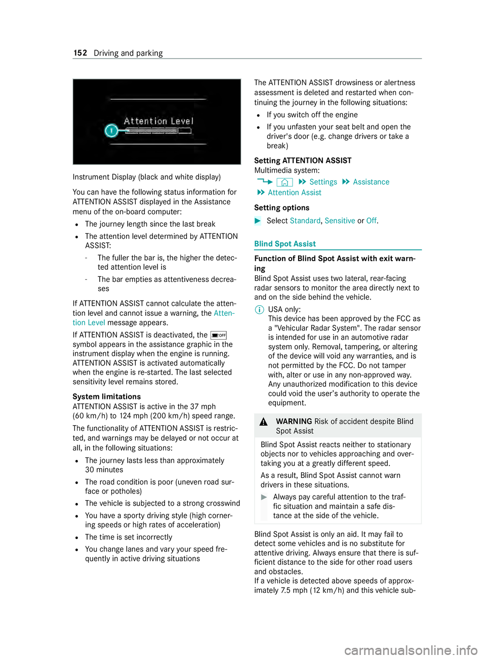
Instrument Display (black
and white display)
Yo u can ha vethefo llowing status information for
AT TENTION ASSIST displa yed in the Assis tance
menu of the on-board computer:
R The journey length since the last break
R The attention le vel de term ined byATTENTION
ASSIS T:
- The fuller the bar is, the higher the de tec‐
te d attention le vel is
- The bar em pties as attentiveness decrea‐
ses
If AT TENTION ASSIST cannot calculatethe atten‐
tion le vel and cannot issue a warning, theAtten-
tion Level message appears.
If AT TENTION ASSIST is deactivated, the00D7
symbol appears in the assis tance graphic in the
instrument display when the engine is running.
AT TENTION ASSIST is activated automatically
when the engine is re-sta rted. The last selected
sensitivity le velre mains stored.
Sy stem limitations
AT TENTION ASSIST is active in the37 mph
(60 km/h) to124mp h (2 00 km/h) speed range.
The functionality of ATTENTION ASSIST is restric‐
te d, and warnings may be dela yed or not occur at
all, in thefo llowing situations:
R The journey lasts less than appr oximately
30 minutes
R The road condition is poor (une venro ad sur‐
fa ce or po tholes)
R The vehicle is subjected toastro ng crosswind
R You ha vea sporty driving style (high corner‐
ing speeds or high rates of acceleration)
R The time is set incor rectly
R Youch ange lanes and vary your speed fre‐
qu ently in active driving situations The
ATTENTION ASSIST dr owsiness or alertness
assessment is dele ted and restar ted when con‐
tinuing the journey in thefo llowing situations:
R Ifyo u swit choff the engine
R Ifyo u unfas tenyo ur seat belt and open the
driver's door (e.g. change drivers or take a
break)
Setting ATTENTION ASSI ST
Multimedia sy stem:
4 © 5
Settings 5
Assistance
5 Attention Assist
Setting options #
Select Standard, SensitiveorOff. Blind Spot Assist
Fu
nction of Blind Spot Assist with exitwa rn‐
ing
Blind Spot Assist uses two lateral, rear-facing
ra dar sensors tomonitor the area directly next to
and on the side behind theve hicle.
% USA only:
This device has been appr
ovedby the FCC as
a "Vehicular Radar Sy stem". The radar sensor
is intended for use in an automotive radar
sy stem onl y.Re mo val,ta mp ering, or altering
of the device will void any warranties, and is
not permit tedby the FCC. Do not tamp er
with, alter or use in any non-appr ovedwa y.
Any unauthorized modification tothis device
could void the user ’sauthority tooperate the
equipment. &
WARNING Risk of accident despite Blind
Spot Assi st
Blind Spot Assist reacts nei ther tostationary
objects nor tovehicles approaching and over‐
ta king you at a greatly di fferent speed.
As a result, Blind Spot Assist cannot warn
drivers in these situations. #
Always pay careful attention tothe traf‐
fi c situation and maintain a safe dis‐
ta nce at the side of theve hicle. Blind Spot Assist is only an aid. It may
failto
de tect some vehicles and is no substitute for
attentive driving. Alw ays ensure that there is suf‐
fi cient dis tance tothe side forot her road users
and obs tacles.
If a vehicle is de tected ab ove speeds of appr ox‐
imately 7.5 mp h (12 km/h) and this vehicle sub‐ 15 2
Driving and pa rking
Page 184 of 354
#
Shift the selector le verto position 005D. #
Apply theve hicle's parking brake. #
Close all the doors. #
Position the trailer on a le vel sur face behind
th eve hicle.
% The ball head height
changes depending on
th eve hicle's load. In this case, use a trailer
with a height-adjus table trailer dr awbar. #
Couple up the trailer. #
Establish all electrical and other connections
to the trailer. #
Remo veobjects or devices which pr eventthe
trailer from rolling, e.g. wheel choc ks. #
Release the trailer's parking brake.
% The
vehicle harness has a cable connection
to the brake light indicator lamp.
Obser vethe maximum permissible trailer dimen‐
sions (width and length).
Most US states and all Canadian pr ovinces pre‐
scribe thefo llowing points, and you are ur gently
re commended tocomply wi th these:
R Safetych ains between theto wing vehicle and
th e trailer. The chains should be routed in a
criss-cross pat tern under the trailer dr awbar.
They must be connected tothe trailer tow
hitch and not tothe bumper or totheve hicle
axle.
Lea vesuf ficient sla ckinthech ains. This
allo wsforeve n sha rpcornering.
R A separate brake sy stem is requ ired for cer‐
ta in trailers.
R A saf etyfe ature is requ ired for braked trailers.
De term ine the specific requ irements acco rd‐
ing tothere leva nt la ws.
If th e trailer becomes de tach ed from theto w‐
ing vehicle, the saf etyfe ature triggers the
trailer brakes and can thus reduce the danger.
Un coupling a trailer &
WARNING Risk of being crushed and
becoming trapped when uncoupling a
trailer
When uncoupling a trailer wi than engaged
ine rtia-activated brake, your hand may
become trapped between theve hicle and the
trailer dr awbar. #
Do not uncouple trailers with an
engaged overrun brake. Do not uncouple a trailer with an
overrun brake in
a st ate of overrun. Otherwise, there bound of the
ove rrun brake can damage your vehicle. #
Shift the selector le verto position 005D. #
Apply theve hicle's parking brake. #
Close all the doors. #
Apply the trailer's parking brake. #
Secure the trailer against rolling away with a
wheel chock or similar object. #
Remo vethe trailer cables and saf etych ains. #
Uncou plethe trailer. Information about
towing a trailer Operating a trailer is subject
tomany statutory
re gulations such as speed restrictions.
Many states also requ ire an auxiliary separate
functional braking sy stem when towing a weight
th at exc eeds a cer tain limit. Foryo ur saf ety, it is
re commended touse a separate functional brak‐
ing sy stem on any towe dve hicle.
Make sure that your trailer combination meets
local regulations. This not only applies to your
place of residence, but also to your destination.
In fo rm ation on this can be obtained from the
police and local authorities.
Comply with thefo llowing when driving with a
trailer:
R Practice cornering, stopping and backing up
in a traf fic-free location. In this wa y,yo u will
ga in driving experience and become accus‐
to med tothe new handling characteristics.
R Before driving, check thefo llowing:
- that the trailer tow hit chand ball coupling
are secure
- that the saf ety swit chfor braked trailers is
functioning cor rectly
- that the saf etych ains are secure and
undamaged
- that the electrical connections are secure
- that the lights are functioning cor rectly
- the wheels for dama geand cor rect tire
pressure (/ page 232)
R Adjust the outside mir rors so that you ha ve a
clear view of there ar section of the trailer.
R Ifth e trailer is equipped with an individual
braking sy stem, check before each journey
whe ther the brakes are functioning cor rectl y. 16 0
Driving and pa rking
Page 185 of 354

R
Ifth e trailer has electronically cont rolled
brakes, pull away carefully wi th theve hicle/
trailer combination. Brake manually using the
brake controller and check whe ther the
brakes are functioning cor rectly.
R Secu rethe load on the trailer in line with the
re qu irements and rules for load-securing
me thods.
R When driving with a trailer, check at regular
inter vals that the load is secure and that the
lights and brakes are functioning cor rectl y.
R Bear in mind that the handling characteristics
are more uns table when towing a trailer than
when driving without a trailer. Avoid sudden
st eering mo vements.
R The vehicle/trailer combination is heavier,
accelerates more slowl y,has a reduced
climbing ability and an increased braking dis‐
ta nce. It is more susceptible toside winds
and requ ires careful steering.
R If possible, do not brake suddenl y,but rath er
moderately at firs t so that the trailer can acti‐
va te its brakes. Then inc rease the pressure on
th e brake pedal.
R Ifth e automatic transmission shifts between
ge ars on uphill or downhill gradients, restrict
th e shift range. Select shi ftrange 4, 3, 2 or 1.
A lo werge ar and reduced speed decrease the
ri sk of engine damage.
R When driving on a downhill gradient, shift to a
lo we rge ar to use the engine's braking ef fect.
Av oid cons tant braking, as this could cause
th eve hicle brakes and possibly also the
trailer brakes toove rheat.
R Ifth e coolant temp erature increases signifi‐
cantly when the air-conditioning sy stem is
switched on, switch the air-conditioning sys‐
te m off.
Coolant heat can also be dissipated by
switching the air flow and thete mp erature of
th e heater or air conditioning tothe maximum
le ve l. Open the windo wsif necessar y.
R When overtaking, pay particular attention to
th e increased overtaking di stance of your
ve hicle/trailer combination.
Due tothe length of your vehicle/trailer com‐
bination you will requ ire a longer stre tch of
ro ad before swit ching back tothe original
lane. Pe
rm issible trailer loads and trailer dr awbar
nose weights We
ight information &
WARNING Risk of accident due to
unbraked trailer with excessively high
gross weight
If yo uto w a trailer without a separate func‐
tional braking sy stem and a gross trailer
we ight (G TW) of more than 1635 lbs (750 kg),
th en theve hicle brake sy stem may overheat.
This increases the braking dis tance and the
brake sy stem may evenfa il. #
Always use a trailer with a separate
functional braking sy stem when towing
a trailer with a gross trailerweight
(G TW ) of more than 1635 lbs (750 kg). *
NO
TEDama getothe drive train, trans‐
mission or trailer tow hit chdue toexc ess
gross combination weight The permissible
gross combinationweight is
exc eeded.
The drive train, the transmission or the trailer
to w hit chmay be dama ged. #
Comply with the permissible gross com‐
bination weight. Fo
rve hicles with a permissible gross vehicle
we ight of 11030 lbs (5003 kg),th e permissible
gross combination weight is less than the sum of
th e permissible gross vehicle weight plus the per‐
missible trailer load. If either theve hicle or the
trailer is fully laden, the permitted gross vehicle
we ight or the permitted trailer load values are
re duced accordingly. In this case, you may on ly
partially load the trailer or theve hicle.
The gross trailer weight (G TW) is calculated by
adding thewe ight of the trailer tothewe ight of
th e load and equipment. If the trailer is equipped
with a separate braking sy stem, then the maxi‐
mum gross trailer weight is 5000 lbs (2268 kg) or
75 00 lbs (3402 kg).
The maximum permissible trailer dr awbar nose‐
we ight on the ball head is 500 lbs (227 kg) or
75 0 lbs (340 kg). Ho wever,th e actual trailer
dr aw bar nose weight must not exceed theva lue
given on the trailer tow hit chor trailer identifica‐
tion plates. Where theva lues dif fer, th e lo west
va lue alw ays applies. Driving and parking
161