2019 MERCEDES-BENZ SPRINTER clock
[x] Cancel search: clockPage 155 of 354

DEF
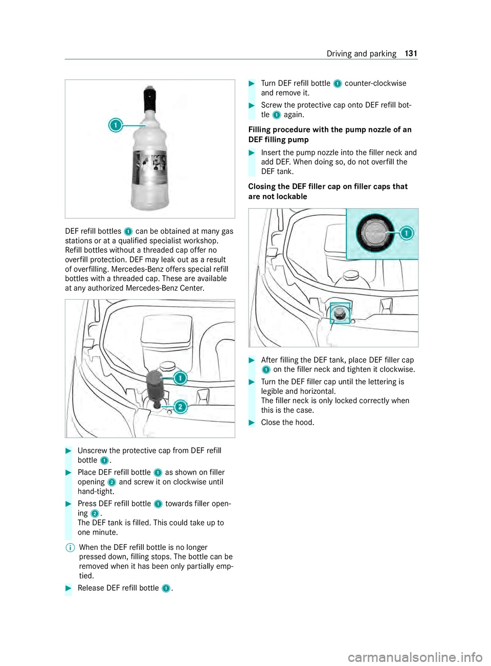
refill bottles 1can be obtained at many gas
st ations or at a qualified specialist workshop.
Re fill bottles without a thre aded cap of fer no
ove rfill pr otection. DEF may leak out as a result
of ove rfilling. Mercedes-Benz of fers special refill
bottles with a thre aded cap. These are available
at any authorized Mercedes-Benz Center. #
Unscr ewthe pr otective cap from DEF refill
bottle 1. #
Place DEF refill bottle 1as shown on filler
opening 2and scr ewit on clockwise until
hand-tight. #
Press DEF refill bottle 1towa rdsfiller open‐
ing 2.
The DEF tank is filled. This could take up to
one minute.
% When
the DEF refill bottle is no longer
pressed down, filling stops. The bottle can be
re mo ved when it has been only partially emp‐
tied. #
Release DEF refill bottle 1. #
Turn DEF refill bottle 1coun ter-clockwise
and remo veit. #
Screw the pr otective cap onto DEF refill bot‐
tle 1 again.
Fi lling procedure with the pu mpnozzle of an
DEF filling pump #
Insert the pump nozzle into thefiller neck and
add DE F.When doing so, do not overfill the
DEF tank.
Closing the DEF filler cap on filler caps that
are not loc kable #
Afterfilling the DEF tank, place DEF filler cap
1 onthefiller neck and tigh ten it clo ckwise. #
Turn the DEF filler cap until the lettering is
legible and horizontal.
The filler neck is only loc ked cor rectly when
th is is the case. #
Close the hood. Driving and parking
131
Page 189 of 354

The on-board computer is operated via left-hand
To uch Control 2and the back button on the left
1. The on-board computer is operated using
thefo l‐
lowing buttons:
R the back button on the left 1
R the left-hand Touch Control 2
R the main menu button on the left 3
The following menus are available:
R Service
R Assistance
R Trip
R Radio
R Media
R Phone
R Settings #
Tocall up the main menu: pressthe back
button on the left 1repeatedly, or press and
hold it.
% Ve
hicles without Active Di stance Assist
DISTRO NIC:you can call up the main menu
of the on-board computer with the00E2 but‐
to n. #
Tobrows eth rough the menu bar: swipeto
th e left or right on left-hand Touch Control
2. #
Tocall up a menu or confirm a selection:
press left-hand Touch Control 2. #
Tobrows eth rough displa ysor lists in the
menu: swipe upwards or down wards on left-
hand Touch Control 2. #
Tocall up a submenu or confirm a selec‐
tion: press left-hand Touch Control 2. #
Toexit a submenu: pressthe back button on
th e left 1.
If yo u are in a submenu and press and hold the
back button on the left 1,the main menu
appears. Overview of
the displa yson the multifunc‐
tion display In
stru ment Display with color display
1 Outside temp erature
2 Transmission position
3 Clock
4 Display section In
stru ment Display with black and white dis‐
play
1 Outside temp erature
2 Display section
3 Clock
4 Transmission position
Fu rther displa yson the multifunction display:
0097 Gearshift
recommendation
é Parking Assist PARKTRONIC swit ched
off
00B2 Cruise cont
rol (/ page 141)
ç Active Dis tance Assi stDISTRONIC
(/ page 143) In
stru ment Display and on-board computer 16 5
Page 195 of 354

Information about Mercedes PRO
When you log in with a user account tothe
Mercedes PRO por tal,th en services and of fers
from Mercedes-Benz Vans will be available to
yo u.
Av ailability is countr y-dependent. You can check
th eav ailability of Mercedes PRO in your country
at thefo llowing page: http://www.me rcedes.pro
Fo r more information on Mercedes PRO contact
an authorized Mercedes-Benz Center or visit the
Mercedes PRO por tal. Information about Mercedes PRO connect
Mercedes PRO connect pr ovides thefo llowing
services:
R Accident and breakdown mana gement
(breakdown assi stance call button or auto‐
matic accident or breakd own de tection)
Use the breakdown assis tance call button in
th eov erhead cont rol panel tomake a call to
th e Mercedes-Benz Cus tomer Center
(/ page 171).
Yo u can also select a menu ent ryinthe multi‐
media sy stem (/ page171).
R Emergency Call Sy stem
Use the0053 button (SOS button) in the
ove rhead cont rol panel tomake a call tothe
Mercedes-Benz emer gency call center
(/ page 171).
Mercedes PRO connect accident and breakdown
management and the Mercedes-Benz emer gency
call center are available foryo u around the clock
fo rth e use of the services.
Please no tethat Mercedes PRO connect is a
Mercedes-Benz service. In emer gencies, al ways
call the national emer gency services firs t using
th est andard national emer gency service phone
numbers. In emergencies, you can also use the
Emergency Call Sy stem (/ page216).
The following conditions must be met touse
Mercedes PRO connect services in theve hicle:
R You ha veaccess toa GSM network
R The contract partner's GSM network co ver‐
age is available in there spective region
R The ignition is switched on, so that vehicle
data can be transfer red automatically Calling the Mercedes-Benz Cus
tomer Center
using the multimedia sy stem
Multimedia sy stem:
4 © 5
Phone 5
g #
Call Mercedes PRO connect.
Then, you can select a service and be connec ted
to a specialist at the Mercedes-Benz Cus tomer
Center. Making a call via the
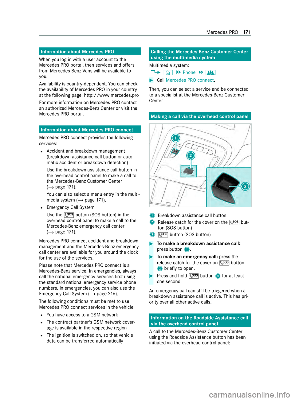
overhead control panel 1
Breakdown assis tance call button
2 Release cat chforth e co ver on the0053 but‐
to n (SOS button)
3 0053 button (SOS button) #
Tomake a breakdown assistance call:
press button 1. #
Tomake an eme rgency call: pressthe
re lease cat chforth e co ver on 0053 button
2 brief lyto open. #
Press and hold 0053button 3for at least
one second.
An emer gency call can still be triggered when a
breakdown assis tance call is acti ve. This has pri‐
ority over all other active calls. Information on
theRo adside Assistance call
via the overhead control panel
A call tothe Mercedes-Benz Cus tomer Center
using theRo adside Assis tance button has been
initia ted via theove rhead cont rol panel: Mercedes PRO
171
Page 224 of 354

#
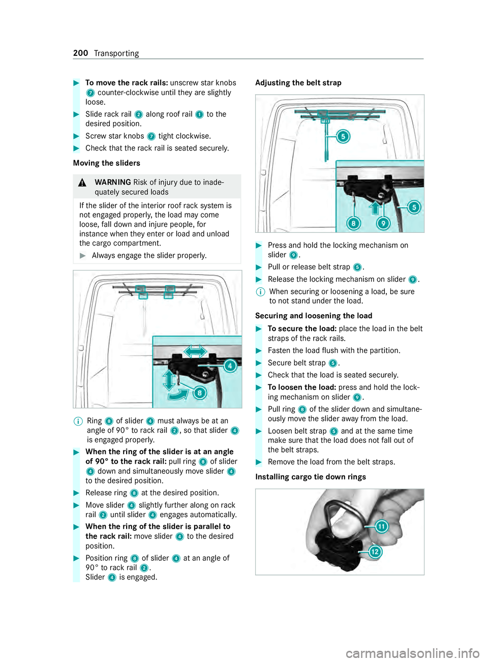
Tomo vetherack ra ils:unsc rew star knobs
7 coun ter-clockwise until they are slightly
loose. #
Slide rack rail2 along roof rail1 tothe
desired position. #
Screw star knobs 7tight clo ckwise. #
Check that thera ck rail is seated securely.
Moving the sliders &
WARNING Risk of inju rydue toinade‐
qu ately secured loads
If th e slider of the interior roof rack system is
not engaged proper ly,th e load may come
loose, fall down and injure people, for
ins tance when they enter or load and unload
th e cargo compartment. #
Always engage the slider properly. %
Ring
8of slider 4must alw ays be at an
angle of 90° torack rail2, so that slider 4
is engaged proper ly. #
When thering of the slider is at an angle
of 90° totherack ra il:pull ring 8 of slider
4 down and simul taneously mo veslider 4
to the desired position. #
Release ring 8 atthe desired position. #
Moveslider 4slightly fur ther along on rack
ra il2 until slider 4engages automaticall y. #
When thering of the slider is pa rallel to
th erack ra il:mo veslider 4tothe desired
position. #
Position ring 8 of slider 4at an angle of
90° torack rail2.
Slider 4is engaged. Ad
justing the belt strap #
Press and hold the locking mechanism on
slider 9. #
Pull or release belt stra p5. #
Release the locking mechanism on slider 9.
% When securing or loosening a load, be sure
to not stand under the load.
Securing and loosening the load #
Tosecure the load: placethe load in the belt
st ra ps of thera ck rails. #
Fasten the load flush with the partition. #
Secure belt stra p5. #
Check that the load is seated securel y. #
Toloosen the load: press and hold the lock‐
ing mechanism on slider 9. #
Pull ring 8 ofthe slider down and simultane‐
ously mo vethe slider away from the load. #
Loosen belt stra p5 and at the same time
make sure that the load does not fall out of
th e belt stra ps. #
Remo vethe load from the belt stra ps.
Installing cargo tie down rings 200
Transporting
Page 230 of 354

&
WARNING Risk offire and injury from
engine oil
If engine oil comes into con tact wi thhot com‐
ponent parts in the engine compartment, it
may ignite. #
Make sure that no engine oil is spilled
next tothefiller opening. #
Allow the engine tocool off and thor‐
oughly clean the engine oil from compo‐
nent parts before starting theve hicle. *
NO
TEEngine damage due toincor rect oil
fi lter, incor rect oil or additi ve #
Do not use engine oil or an oil filter with
specifications deviating from those
re qu ired forth e prescribed service
inter vals.
Mercedes-Benz recommends using original or
te sted replacement and service parts. #
Do not change the engine oil or oil filter
in order toset change inter vals longer
th an those prescribed. #
Do not use any additive. #
Follow the instructions on the service
inter val display forch anging the engine
oil. *
NO
TEDama gecaused byadding too
much engine oil To
o much engine oil can damage the engine
or the catalytic con verter. #
Have excess engine oil remo ved at a
qu alified specialist workshop. Engine OM651
Engine OM642
#
Turn cap 1counter-clockwise and remo veit. #
Add engine oil. #
Replace cap 1and turn it clockwise until it
engages. #
Check the oil le vel again . Check using the on-
board computer (/ page 205),check with
th e oil dipstick (/ page 204). Checking
the coolant le vel &
WARNING Risk of bu rns from hot com‐
ponent parts in the engine compartment
Cer tain components in the engine compart‐
ment can be very hot, e.g. the engine, the
ra diator and parts of theex haust sy stem. #
Allow the engine tocool down and only
to uch component parts desc ribed in the
fo llowing. 206
Maintenance and care
Page 231 of 354

If
yo u ha vetocar ryout any workinthe engine
compartment, touch only thefo llowing compo‐
nents:
R Hood
R Engine oil filler opening cap
R Washer fluid reser voir cap
R Coolant expansion reser voir cap &
WARNING Danger of bu rns when open‐
ing the hood
If yo u open the hood when the engine has
ove rheated or during a fire inthe engine com‐
partment, you could come into con tact wi th
hot gases or other escaping operating fluids. #
Before opening the hood, allow the
engine tocool down. #
Intheeve nt of a fire inthe engine com‐
partment, keep the hood closed and call
th efire service. &
WARNING Risk of scalding from hot
coolant
The engine cooling sy stem is pressurized,
particular lywhen the engine is warm. If you
open the cap, you could be scalded byhot
coolant spr aying out. #
Let the engine cool down before open‐
ing the cap. #
When opening the cap, wear pr otective
gl ove s and saf etygl asses. #
Open the cap slowly torelease pres‐
sure. Allow
the engine and the engine cooling sy stem
to cool down before checking the coolant le vel or
re filling coolant.
* NO
TEPaint wo rkdamage due tocoolant If coolant
gets on painted sur faces, the paint‐
wo rkcan be damaged. #
Add coolant carefully. #
Remo vespilled coolant. Checking
the coolant le vel Example: coolant
expansion reser voir #
Park theve hicle on an even sur face. #
Open the hood (/ page 202). #
Slowly turn coolant expansion reser voir cap
1 half a turn coun ter-clockwise and allow
exc ess pressure toescape. #
Turn coolant expansion reser voir cap 1fur‐
th er and remo veit. #
Check the coolant le vel.
There is enough coolant in coolant expansion
re ser voir if the coolant reaches the MAX
mar k.
Ad ding coolant #
Refill th e coolant tothe MAX mark on the
coolant expansion reser voir.
Only use coolant appr oved byMercedes-Benz to
avo id damaging the engine cooling sy stem. #
Replace coolant expansion reser voir cap 1
and tigh ten in a clo ckwise direction. #
Start the engine. #
After appro ximately five minutes, switch off
th e engine again and allow it tocool down. #
Che ckthe coolant le vel again and add coolant
if necessar y.
% Obser
veadditional coolant information
(/ page 269). Main
tenance and care 207
Page 245 of 354

R
vehicles with a gasoline engine: only per‐
fo rm starting assis tance when the engine and
ex haust sy stem are cold #
Vehicles with a battery main switch: check
whe ther the battery main switch is switched
on (/ page114). #
Secu retheve hicle using the parking brake. #
Vehicles with automatic transmission:
shift the transmission toposition 005D. #
Switch off the ignition and all electrical con‐
sumers. #
Open the hood (/ page 202). Example: jump-s
tart connection point
% Right-hand-drive
vehicles: the jump-s tart
connection points may be on the opposite
side. #
Remo vethe co ver from the positive term inal
on the donor batter y. #
First, connect the positive term inal clamp of
th e jumper cables/charging cables tothe
positive term inal of theot her vehicle's bat‐
te ry. #
With positive term inal clamp 2ofthe
jumper cable, slide there d pr otective cap on
jump-s tart connection point 1back with a
clockwise turn. #
Connect the positive term inal clamp tothe
positive term inal of jump-s tart connection
point 1. #
During starting assistance: start the engine
of the donor vehicle and let it run at idle
speed. #
Connect the negative term inal of the donor
battery tothe ground point of your ow nve hi‐ cle with
the jumper cable/charging cable.
Begin with the donor batter y. #
During starting assistance: start the engine
on your ow nve hicle. #
When charging: start thech arging process. #
During starting assistance: letthe engine
ru nfo r a few minutes. #
During starting assistance: before discon‐
necting the jumper cable, switch on an elec‐
trical consumer on your ow nve hicle, e.g. the
re ar wind owheater or lighting.
When thest arting assis tance/charging process is
comple te: #
First,re mo vethe jumper cables/charging
cables from the ground point and negative
te rm inal of theot her vehicle's batter y,then
from the positive term inal of jump-s tart con‐
nection point 1and the positive term inal of
th eot her vehicle's batter y.Each time, begin
at the contacts on your ow nve hicle.
The red pr otective cap springs back toits ini‐
tial position when positive term inal clamp 2
is disconnected from jump-s tart connection
point 1.
Fu rther information can be obtained at a qualified
specialist workshop. Installing/removing
thefloor co vering (vehi‐
cles with rear wheel drive) &
WARNING Risk of accident due to
objects in the driver's foot we ll
Objects in the driver's foot we ll may impede
pedal tr avel or block a depressed pedal.
This jeopardizes the operating and road
saf ety of theve hicle. #
Stow all objects in theve hicle securely
so that they cannot getinto the driver's
fo ot we ll. #
Ensure floor mats and carpets cannot
slip and pr ovide suf ficient room forthe
pedals. #
Do not lay multiple floor mats or carpets
on top of one ano ther. Breakdown assis
tance 221
Page 251 of 354

#
Obser vethe no tes on permissible towing
me thods (/ page 224). #
The propeller shafts tothe drive axles must
be remo ved if the maximum permissible tow‐
ing dis tance is exceeded. #
Vehicles with automatic transmission:
shift the automatic transmission toposition
005C. #
Release the parking brake. #
Switch off the ignition. Loading
theve hicle for transport #
Obser vethe no tes on towing away
( / page 225) (/ page 226). #
Connect theto w bar totheto wing eyeto load
th eve hicle. #
Vehicles with automatic transmission:
shift the automatic transmission toposition
005C.
% Ve
hicles with automatic transmission: in
th eeve nt of damage tothe electrics, the
automatic transmission may be loc ked in
position 005D.Toshift toposition 005C, provide
th e on-board electrical sy stem with po wer
( / page 219). #
Load theve hicle onto the transpor ter. #
Vehicles with automatic transmission:
shift the automatic transmission toposition
005D. #
Use the parking brake tosecure theve hicle
against rolling away. #
Only secure theve hicle bythe wheels.
Ve hicles with all-wheel drive/vehicles with
automatic transmission #
Make sure that the front and rear axles come
to rest on the same transpor tation vehicle. *
NO
TEDama getothe driv etra in due to
incor rect positioning #
Do not position theve hicle abo vethe
connection point of the transport vehi‐
cle. *
NO
TEVehicle damage due toimproper
loading An all-wheel drive
vehicle may be damaged if
it is tilted, pushed or mo ved while being loa‐
ded using a hydraulic platform. #
When loading a vehicle with all-wheel
drive, theve hicle should only be mo ved
and positioned byits own po wer. #
The vehicle and the sur face it is posi‐
tioned on should no longer be mo ved
when theke y is remo ved or if the door
is open. To
wing eyesto rage location The
towing eye is located in theve hicle tool kit in
th e front-passen gerfo ot we ll (/ page 229). Installing/removing
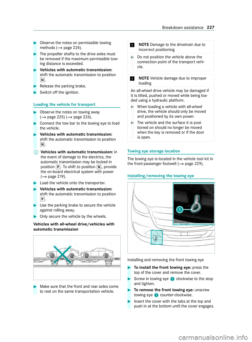
theto wing eye Ins
talling and removing the front towing eye #
Toinstall the front towing eye: press the
to p of the co ver and remo vethe co ver. #
Screw intowing eye1clockwise tothestop
and tighten. #
Toremo vethe front towing eye: unsc rew
to wing eye1 counter-clockwise. #
Insert the co ver with theta bs at theto p and
push in at the bottom until the co ver engages. Breakdown assi
stance 227