2019 MERCEDES-BENZ SPRINTER change wheel
[x] Cancel search: change wheelPage 105 of 354

The function is active under
thefo llowing condi‐
tions:
R The speed is less than 37 mph (60 km/h) and
th e indicator has been switched on or the
st eering wheel is turned.
R The speed is between 37mph (60 km/h) and
50 mph (8 0 km/h) and thesteering wheel is
turned.
The cornering light may still light up for a short
time but is switched off automatically af ter a
maximum of thre e minutes.
% When
reve rsege ar is engaged, the lighting
switches tothe opposite side. Highbeam Assist
Ad
aptive Highbeam Assist function &
WARNING Risk of accident despite
Ad aptive Highbeam Assist
Ad aptive Highbeam Assist does not recognize
th efo llowing road users:
R Road users without lights, e.g. pedes‐
trians
R Road users with poor lighting, e.g. cyclists
R Road users whose lighting is obstructed,
e.g. bya bar rier
On very rare occasions, Adaptive Highbeam
Assist may failto recognize other road users
with their own lighting, or may recognize
th em too late.
In these or similar situations, the automatic
high beam is not deactivated or is activated
despite the presence of other road users. #
Always obser vethe tra ffic carefully and
switch off the high beam in good time. The
Adaptive Highbeam Assist automatically
swit ches between thefo llowing settings:
R Low beam
R High beam
The sy stem de tects that vehicle lights are
approaching in the opposite direction or driving
ahead of theve hicle.
At speeds greater than 19 mp h (30 km/h), a
ch ange is made tothefo llowing setting:
R If no other road users are de tected, the high
beam switches on automaticall y.At
speeds less than 16 mp h (25 km/h) or if there
is suf ficient road lighting, a change is made to
th efo llowing setting:
R The high beam automatically switches off.
Sy stem limitations
Ad aptive Highbeam Assist cannot take thero ad,
we ather or traf fic conditions into consideration.
The de tection of obs tacles can be restricted if:
R Visibility is impaired, e.g. in fog, heavy rain or
snow
R The sensors are dirty or co vered
Ad aptive Highbeam Assist is only an aid. You are
re sponsible for ensuring cor rect vehicle lighting
in accordance with the pr evailing light, visibility
and traf fic conditions.
The sy stem's optical sensor is located behind the
windshield near theove rhead cont rol panel.
Switching Highbeam Assist on or off #
Toswitch on: turnthe light switch tothe
0058 position. #
Switch the highbeam on using the combina‐
tion switch.
If th e highbeam is automatically switched on
in darkness, the 00CE indicator lamp on the
multifunction display lights up. #
Toswitch off: switch offthe highbeam using
th e combination switch. Setting
theex terior lighting switch-off delay
time Re
quirements:
R The light switch is in position 0058.
Multimedia sy stem:
4 © 5
Settings 5
Light
5 Ext. Light Switch-off #
Set a switch-off delay time.
When theve hicle engine is switched off, theex te‐
ri or lighting will be activated forth e set time. Ac
tivating and deactivating the sur round
lighting Multimedia sy
stem:
4 © 5
Settings 5
Light
5 Locator Lighting #
Activate or deacti vate the function. Light and vision
81
Page 109 of 354
#
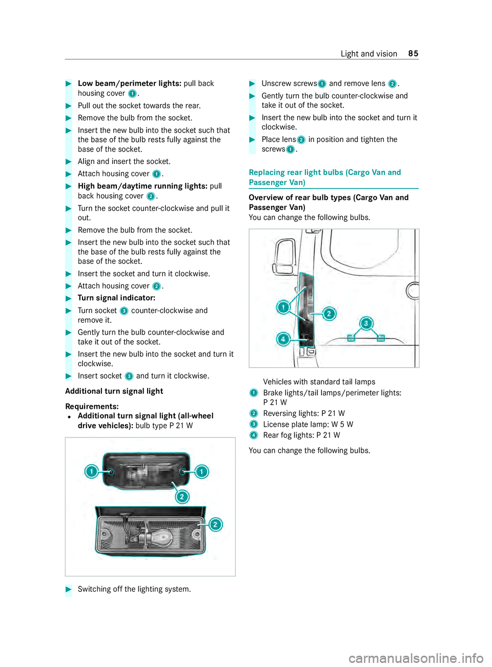
Low beam/perime ter lights: pull back
housing co ver1. #
Pull out the soc ketto wa rdsth ere ar. #
Remo vethe bulb from the soc ket. #
Inse rtthe new bulb into the soc ket su chthat
th e base of the bulb rests fully against the
base of the soc ket. #
Align and insert the soc ket. #
Attach housing co ver1. #
High beam/daytime running lights: pull
back housing co ver2. #
Turn the soc ket counter-clo ckwise and pull it
out. #
Remo vethe bulb from the soc ket. #
Inse rtthe new bulb into the soc ket su chthat
th e base of the bulb rests fully against the
base of the soc ket. #
Inse rtthe soc ket and turn it clo ckwise. #
Attach housing co ver2. #
Turn signal indicator: #
Turn soc ket3 counter-clo ckwise and
re mo veit. #
Gently turn the bulb counter-clockwise and
ta ke it out of the soc ket. #
Inse rtthe new bulb into the soc ket and turn it
clo ckwise. #
Insert soc ket3 and turn it clo ckwise.
Ad ditional turn signal light
Re quirements:
R Ad
ditional turn signal light (all-wheel
drive vehicles): bulb type P 21 W #
Switching off the lighting sy stem. #
Unscr ewscrews 1and remo velens 2. #
Gently turn the bulb counter-clockwise and
ta ke it out of the soc ket. #
Inse rtthe new bulb into the soc ket and turn it
clo ckwise. #
Place lens 2in position and tigh tenthe
scr ews 1. Re
placing rear light bulbs (Cargo Van and
Pa ssenger Van) Overview of
rear bulb types (Cargo Van and
Pa ssenger Van)
Yo u can change thefo llowing bulbs. Ve
hicles with standard tail lamps
1 Brake lights/tail lamps/pe rime ter lights:
P 21 W
2 Reversing lights: P 21 W
3 License plate lamp: W 5 W
4 Rear fog lights: P 21 W
Yo u can change thefo llowing bulbs. Light and vision
85
Page 141 of 354
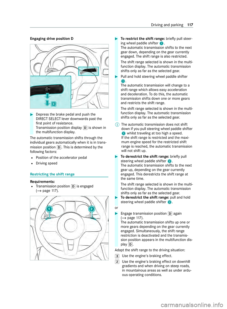
Engaging drive position D
#
Dep ress the brake pedal and push the
DIRECT SELECT le ver down wards past the
fi rs t point of resis tance.
Tr ansmission position display 005Bis shown in
th e multifunction displa y.
The automatic transmission shifts thro ugh the
individual gears automatically when it is in trans‐
mission position 005B. This is determ ined bythe
fo llowing factors:
R Position of the accelerator pedal
R Driving speed Re
stricting the shift range Re
quirements:
R Transmission position 005Bis engaged
(/ page 117). #
Torestrict the shift range: briefly pull steer‐
ing wheel paddle shif ter1.
The automatic transmission shifts tothe next
ge ar down, depending on thege ar cur rently
engaged. The shi ftrange is also restricted.
The shi ftrange selected is shown in the multi‐
function displa y.The automatic transmission
shifts only as far as the selected gear. #
Pull and hold steering wheel paddle shif ter
1 .
The automatic transmission will change to a
shift range which allo wseasy acceleration
and deceleration. Todo this, the automatic
transmission shifts down one or more gears
and restricts the shift range.
The shi ftrange selected is shown in the multi‐
function displa y.The automatic transmission
shifts only as far as the selected gear.
% The automatic transmission does not shift
down if
you pull steering wheel paddle shif ter
1 whilst tr aveling at too high a speed.
If th e shift range is restricted and the maxi‐
mum engine speed forth ere stricted shi ft
ra nge is reached, the automatic transmission
will not shift up. #
Toderestrict the shi ftrange: briefly pull
st eering wheel paddle shif ter2.
The automatic transmission shifts tothe next
ge ar up, depending on thege ar cur rently
engaged. This de restricts the shift range at
th e same time.
The shift range selected is shown in the multi‐
function displa y.The automatic transmission
shifts only as far as the selected gear. #
Toderestrict the shi ftrange: pull and hold
st eering wheel paddle shif ter2.
or #
Engage transmission position 005Bagain
(/ page 117).
The automatic transmission shi fts up one or
more gears depending on thege ar cur rently
engaged. Simultaneously, the shift range
re striction is deactivated and the transmis‐
sion position appears in the multifunction dis‐
play 005B.
Ad apt the shift range tothe driving situation:
0049 Use
the engine's braking ef fect.
0048 Use
the engine's braking ef fect on downhill
gradients and when driving on steep roads,
in mountainous areas as well as under ardu‐
ous operating conditions. Driving and parking
117
Page 167 of 354

#
Todeactivate cruise control: pushrock er
switch 3(CNCL) down.
If cruise cont rol is deactivated, it can be reactiva‐
te d as follo ws:
R rock er switch 2(SET+) or (SET-) stores the
cur rent speed and theve hicle maintains this
speed
R rock er switch 3(RES) calls up the last speed
st ored and theve hicle maintains this speed
% Ifyo u brake, deactivate ESP ®
or if ESP ®
inter‐
ve nes, cruise control is deacti vated.
When you swit choff theve hicle, the last
speed stored is cleared. Ac
tive Di stance Assist DISTRO NICFu
nction of Active Di stance Assist DISTRO NIC
Ac tive Dis tance Assi stDISTRONIC maintains the
set speed on free-flowing roads. If vehicles ahead
are de tected, the set dis tance is maintained, if
necessa ryuntil theve hicle comes toa halt. The
ve hicle accelerates or brakes depending on the
dis tance totheve hicle in front and the set speed.
Speed and dis tance are set and stored on the
st eering wheel. The speed can be set in thera nge
between 15mp h (20 km/h) and 99 mph
(160 km/h) or between 15mp h (20 km/h) and
th eve hicle's maximum speed.
Other features of Active Dis tance Assi st
DISTRONIC:
R Depending on the preselected dis tance,
DISTRONIC inter venes ei ther dynamically
(short dis tance) or tosave fuel (long dis‐
ta nce).
R Depending on theve hicle mass de tected, the
dynamics of the DISTRONIC inter vention are
re duced.
R Rapid acceleration tothestored speed is initi‐
ated if the turn signal indicator is switched on
to change totheov ertak ing lane.
Ac tive Dis tance Assi stDISTRONIC is only an aid.
The driver is responsible forth e dis tancetothe
ve hicle in front, forve hicle speed and for braking
in good time.
Sy stem limitations
The sy stem may be impaired or may not function
in thefo llowing ins tances:
R The radar sensors are af fected bysno w,rain,
fo g, heavy spr ay,gl are, direct sunlight or
greatly varying ambient light. R
The radar sensors may malfunction in parking
ga rage s or on roads with steep uphill or
downhill gradients.
R Ifth era dar sensors are dirty or co vered.
R On icy or slippery roads, braking or accelerat‐
ing can cause the drive wheels tolose trac‐
tion and theve hicle could then skid.
R Stationary objects are not de tected if these
we renot pr eviously de tected as moving.
R On bends, target vehicles may be lost or not
re cognized cor rectl y.As a result, a target
ve hicle is not used toregulate the speed
which may lead tounwa nted accele ration.
Do not use Active Dis tance Assi stDISTRONIC in
th ese situations. &
WARNING Risk of accident from acceler‐
ation or braking byActive Dis tance Assi st
DISTRONIC
Ac tive Dis tance Assi stDISTRONIC may accel‐
erate or brake in thefo llowing cases, for
ex ample:
R Ifth eve hicle pulls away using Active Dis‐
ta nce Assi stDISTRONIC.
R Ifth estored speed is called up and is con‐
siderably faster or slo werth an the cur‐
re ntly driven speed.
R IfAc tive Dis tance Assi stDISTRONIC no
longer de tects a vehicle in front or does
not react toreleva nt objects. #
Always carefully obser vethe traf fic con‐
ditions and be ready tobrake at all
times. #
Take into account the tra ffic situation
before calling up thestored speed. &
WARNING Risk of accident due toinsuf‐
fi cient deceleration byActive Dis tance
Assi stDISTRONIC
Ac tive Dis tance Assi stDISTRONIC brakes
yo ur vehicle with up to50% of the maximum
possible deceleration. If this deceleration is
not suf ficient, Active Dis tance Assi st
DISTRONIC alerts you with a visual and
acoustic warning. #
Inthese cases, adjust your speed and
ke ep a suf ficient dis tance. #
Brake theve hicle yourself and/or take
ev asive action. Driving and parking
14 3
Page 171 of 354
Re
ar view camera Fu
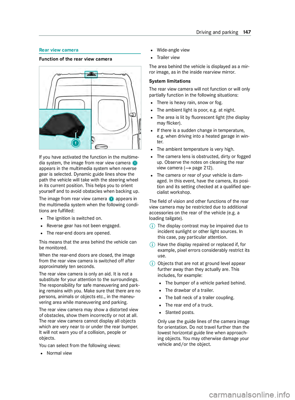
nction of there ar view camera If
yo u ha veactivated the function in the multime‐
dia sy stem, the image from rear view camera 1
appears in the multimedia sy stem when reve rse
ge ar is selec ted. Dynamic guide lines show the
path theve hicle will take with thesteering wheel
in its cur rent position. This helps youto orient
yo urself and toavo id obs tacles when ba cking up.
The image from rear view camera 1appears in
th e multimedia sy stem when thefo llowing condi‐
tions are fulfilled:
R The ignition is switched on.
R Reversege ar has not been engaged.
R The rear-end doors are opened.
This means that the area behind theve hicle can
be monitored.
When there ar-end doors are closed, the image
from there ar view camera is swit ched off af ter
appr oximately ten seconds.
The rear view camera is only an aid. It is not a
substitute foryo ur attention tothe sur roundings.
The responsibility for safe maneu vering and pa rk‐
ing remains with you. Make sure that there are no
persons, animals or objects etc., in the maneu‐
ve ring area while maneuvering and pa rking.
The rear view camera may show a dis torted view
of obs tacles, show them incor rectly or not at all.
The rear view camera cannot display all objects
which are very near toor under there ar bumper.
It will not warnyou of a collision, people or
objects.
Yo u can select from thefo llowing vie ws:
R Norma l view R
Wide-angle view
R Trailer view
The area behind theve hicle is displa yed as a mir‐
ro r image, as in the inside rearview mir ror.
Sy stem limitations
The rear view camera will not function or will only
partially function in thefo llowing situations:
R There is heavy rain, snow or fog.
R The ambient light is poor, e.g. at night.
R The area is lit byfluorescent light (the displ ay
may flic ke r).
R Ifth ere is a sudden change in temp erature,
e.g. when driving into a heated garage in win‐
te r.
R The ambient temp erature is very high.
R The camera lens is obstructed, dirty or fogged
up. Obser vethe no tes on cleaning there ar
view camera (/ page212).
R The camera or rear of your vehicle is dam‐
aged. In this event, ha vethe camera, its posi‐
tion and its setting checked at a qualified spe‐
cialist workshop.
The field of vision and other functions of there ar
view camera may be restricted due toadditional
accesso ries on there ar of theve hicle (e.g. a
loading tailgate).
% The display contrast may be impaired due
to
incident sunlight or other light sources. In
th is case, pay particular attention.
% Ha
ve the display repaired or replaced if, for
ex ample, pixel er rors considerably restrict its
use.
% Objects that are not at ground le vel appear
fur ther aw ay than they actually are. This
includes, forex ample:
R The bumper of a vehicle par ked behind.
R The dr awbar of a trailer.
R The ball neck of a trailer coupling.
R The rear end of a truc k.
R Slanted posts.
Only use the guide lines of the camera image
fo r orientation. Do not tr avel fur ther than the
lo west horizontal guide line when approach‐
ing objects. You may otherwise damage your
ve hicle and/or the object. Driving and parking
147
Page 172 of 354
Ve
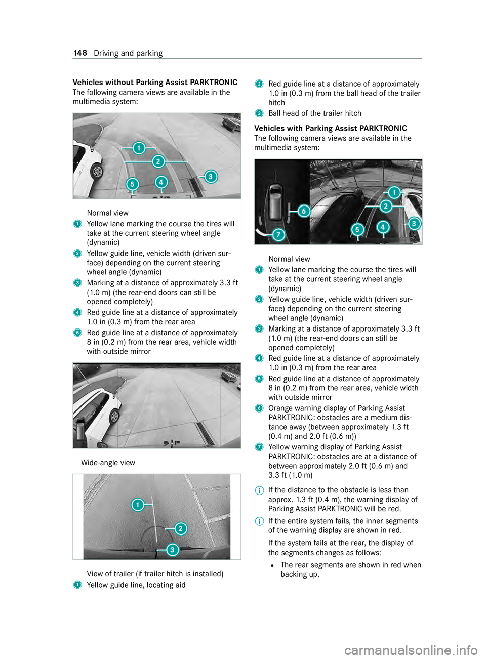
hicles without Parking Assist PARKTRONIC
The following camera vie wsare available in the
multimedia sy stem: Normal view
1 Yellow lane marking the course the tires will
ta ke atthe cur rent steering wheel angle
(dynamic)
2 Yellow guide line, vehicle width (driven sur‐
fa ce) depending on the cur rent steering
wheel angle (dynamic)
3 Marking at a dis tance of appr oximately 3.3 ft
(1.0 m) (the rear-end doors can still be
opened comple tely)
4 Red guide line at a dis tance of appr oximately
1. 0 in (0.3 m) from there ar area
5 Red guide line at a dis tance of appr oximately
8 in (0.2 m) from there ar area, vehicle width
with outside mir ror Wi
de-angle view Vi
ew of trailer (if trailer hitch is ins talled)
1 Yellow guide line, locating aid 2
Red guide line at a dis tance of appr oximately
1. 0 in (0.3 m) from the ball head of the trailer
hitch
3 Ball head of the trailer hitch
Ve hicles with Parking Assist PARKTRONIC
The following camera vie wsare available in the
multimedia sy stem: Normal view
1 Yellow lane marking the course the tires will
ta ke atthe cur rent steering wheel angle
(dynamic)
2 Yellow guide line, vehicle width (driven sur‐
fa ce) depending on the cur rent steering
wheel angle (dynamic)
3 Marking at a dis tance of appr oximately 3.3 ft
(1.0 m) (the rear-end doors can still be
opened comple tely)
4 Red guide line at a dis tance of appr oximately
1. 0 in (0.3 m) from there ar area
5 Red guide line at a dis tance of appr oximately
8 in (0.2 m) from there ar area, vehicle width
with outside mir ror
6 Orange warning display of Parking Assist
PA RKTRONIC: obstacles are a medium dis‐
ta nce away (between appr oximately 1.3 ft
(0.4 m) and 2.0 ft(0.6 m))
7 Yellow warning display of Parking Assist
PA RKTRONIC: obstacles are at a dis tance of
between appr oximately 2.0 ft(0.6 m) and
3.3 ft(1.0 m)
% If
th e dis tance tothe obs tacle is less than
appr ox.1. 3 ft (0.4 m), thewa rning display of
Pa rking Assist PARKTRONIC will be red.
% If
th e entire sy stem fails, the inner segments
of thewa rning display are shown in red.
If th e sy stem fails at there ar, the display of
th e segments changes as follo ws:
R The rear segments are shown in red when
backing up. 14 8
Driving and pa rking
Page 173 of 354
R
The rear segments are hidden when driv‐
ing forw ards.
If Pa rking Assist PARKTRONIC is deactivated,
th ewa rning display fades out. Wi
de-angle view Vi
ew of trailer (if trailer hitch is ins talled)
1 Yellow guide line, locating aid
2 Red guide line at a dis tance of appr oximately
1. 0 in (0.3 m) from the ball head of the trailer
hitch
3 Ball head of the trailer hitch 360° Camera
Fu
nction of the 360° Camera
The 360° Camera is a sy stem that consists of
fo ur cameras. The cameras co verth e immediate
ve hicle sur roundings. The sy stem assists you,
e.g. when parking or at exits with reduced visibil‐
ity.
The 360° Camera is only an aid. It is not a substi‐
tute foryo ur attention tothe sur roundings. The
re sponsibility for safe maneu vering and pa rking
re mains with you. Make sure that there are no
persons, animals or objects etc., in the maneu‐
ve ring area while maneuvering and pa rking.
The sy stem evaluates images from thefo llowing
cameras:
R Rear view camera
R Front camera R
Two side cameras in the outside mir rors
Vi ew s of the 360° Camera
Yo u can select from dif fere nt vie ws:
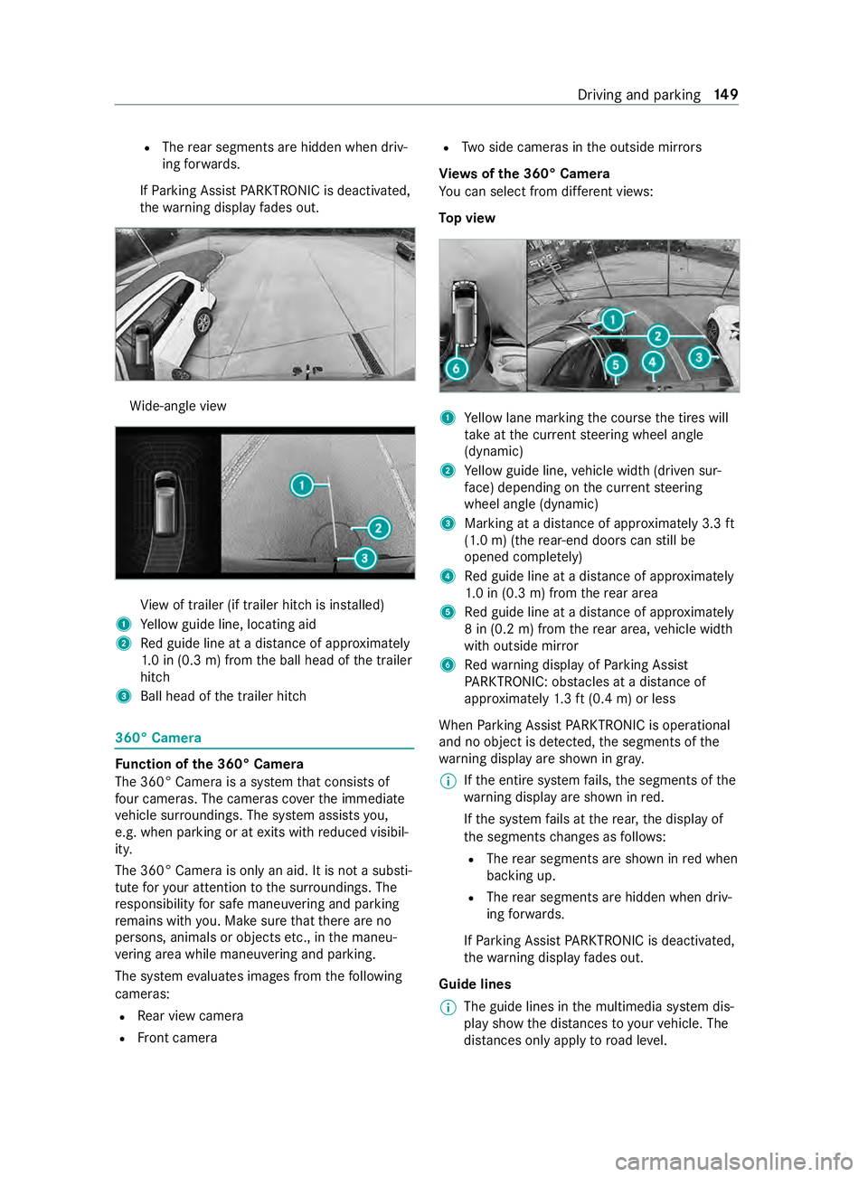
To p view 1
Yellow lane marking the course the tires will
ta ke atthe cur rent steering wheel angle
(dynamic)
2 Yellow guide line, vehicle width (driven sur‐
fa ce) depending on the cur rent steering
wheel angle (dynamic)
3 Marking at a dis tance of appr oximately 3.3 ft
(1.0 m) (the rear-end doors can still be
opened comple tely)
4 Red guide line at a dis tance of appr oximately
1. 0 in (0.3 m) from there ar area
5 Red guide line at a dis tance of appr oximately
8 in (0.2 m) from there ar area, vehicle width
with outside mir ror
6 Redwa rning display of Parking Assist
PA RKTRONIC: obstacles at a dis tance of
appr oximately 1.3 ft (0.4 m) or less
When Parking Assist PARKTRONIC is operational
and no object is de tected, the segments of the
wa rning display are shown in gray.
% If
th e entire sy stem fails, the segments of the
wa rning display are shown in red.
If th e sy stem fails at there ar, the display of
th e segments changes as follo ws:
R The rear segments are shown in red when
backing up.
R The rear segments are hidden when driv‐
ing forw ards.
If Pa rking Assist PARKTRONIC is deactivated,
th ewa rning display fades out.
Guide lines
% The guide lines in
the multimedia sy stem dis‐
play show the dis tances toyour vehicle. The
dis tances only apply toroad le vel. Driving and parking
14 9
Page 174 of 354

In trailer mode,
the guide lines are shown at
th e le vel of the trailer hitch.
Vi ew of trailer (if trailer hit chis installed) Vi
ew of trailer (if trailer hitch is ins talled)
1 Yellow guide line, locating aid
2 Red guide line at a dis tance of appr oximately
1. 0 in (0.3 m) from the ball head of the trailer
hitch
3 Ball head of the trailer hitch
Side view of the mir ror came ras
The sides of theve hicle can be seen in this vie w. 1
Lane indicating thero ute theve hicle will take
with thesteering wheel in its cur rent position
2 Yellow warning display of Parking Assist
PA RKTRONIC: obstacles at a dis tance of
appr oximately 3.3 ft(1.0 m) or less
3 Your vehicle from abo ve
4 Marker of the wheel contact points
5 Guide line of extern al vehicle dimensions
with outside mir rors folded out
If th e dis tance tothe object lessens, the color of
wa rning display 2changes.
Sy stem failure
If th ere is no operational readiness, thefo llowing
message appears in the multimedia sy stem: Sy
stem limitations
The 360° Camera will not function or will only
partially function in thefo llowing situations:
R The front doors are open.
R The side mir rors are folded in.
R There is heavy rain, snow or fog.
R The ambient light is poor, e.g. at night.
R The area is lit byfluorescent light (the displ ay
may flic ke r).
R Ifth ere is a sudden change in temp erature,
e.g. when driving into a heated garage in win‐
te r.
R The ambient temp erature is very high.
R The camera lens is obstructed, dirty or fogged
up.
R Cameras, or vehicle components in which the
came ras are ins talled, are damaged. In this
eve nt, ha vethe cameras, their positions and
th eir setting checked at a qualified specialist
wo rkshop.
Do not use the 360° Camera under such circum‐
st ances. You could otherwise injure others or col‐
lide with objects when parking theve hicle.
On vehicles with height-adjus table suspension or
if th eve hicle is car rying a heavy load, leaving the
st andard height can result in inaccuracies in the
guide lines and in the display of thege nerated
ima ges, depending on tech nical conditions.
The field of vision and other functions of the cam‐
era sy stem may be restricted due toadditional
attachments on theve hicle (e.g. loading tailgate).
% The contrast of
the display may be impaired
by abrupt direct sunlight or by other light
sources, e.g. when driving out of a garage . In
th is case, pay particular attention.
% Ha
ve the display repaired or replaced if, for
ex ample, pixel er rors considerably restrict its
use. 15 0
Driving and pa rking