2019 MERCEDES-BENZ SPRINTER change wheel
[x] Cancel search: change wheelPage 272 of 354
Maximum permissible pa
yload weight: nomi‐
nal load and luggage load plus 150 lbs (68 kg)
multiplied bythe number of seats in theve hicle. Changing a wheel
Note
s on selecting, installing and replacing
tires Yo
u can ask for information rega rding permit ted
wheel/tire combinations at a qualified specialist
wo rkshop. &
WARNING Risk of accident due toincor‐
re ct sizes of wheels and tires
If wheels and tires of the wrong size are used,
th e wheel brakes or wheel suspension com‐
ponents may be damaged. #
Alwaysre place wheels and tires with
ones that fulfill the specifications of the
original part.
Fo r wheels, pay attention tothefo llowing:
R Designation
R Type
R Perm issible wheel load
R Wheel of fset
Fo r tires, pay attention tothefo llowing:
R Designation
R Manufacturer
R Type
R Load-bearing index
R Speed rating &
WARNING Risk of inju rythro ugh exceed‐
ing the specified tire load rating or the
permissible speed rating
Exceeding the specified tire load rating or the
permissible speed rating may lead totire
dama geand tothe tires bur sting. #
Therefore, only use tire types and sizes
appr ovedfo ryo ur vehicle model. #
Obser vethe tire load rating and speed
ra ting requ ired foryo ur vehicle. *
NO
TEVehicle and tire damage thro ugh
tire types and sizes that ha venot been
appr oved Fo
r saf etyre asons, only use tires, wheels and
accesso ries which ha vebeen specially
appr ovedby Mercedes-Benz foryo ur vehicle.
These tires ha vebeen specially adap tedfor
use with the cont rol sy stems, such as ABS or
ESP ®
.
Otherwise, cer tain properties, such as han‐
dling characteristics, vehicle noise and con‐
sum ption could be adversely af fected. Fur‐
th ermore, other tire size could result in the
tires rubbing against the body and axle com‐
ponents when loaded. This could result in
damage tothe tire or theve hicle. #
Only use tires, wheels and accessories
th at ha vebeen checked and recommen‐
ded byMercedes-Benz. *
NO
TEDriving sa fety put at risk by retrea‐
ded tires Re
treaded tires are not checked or recom‐
mended byMercedes-Benz, as pr evious dam‐
age is not alw ays de tected du ring there tread
process.
Driving sa fety cannot, therefore, be guaran‐
te ed. #
Do not use used tires when their pr evi‐
ous usage is unknown. *
NO
TEDama getoelectronic component
parts thro ugh the use of tire-ins talling
to ols Ve
hicles with a tire pressure monitoring
sy stem: there are electronic component
parts in the wheel. Tire -ins talling tools should
not be applied in the area of theva lve.
Otherwise, the electronic component parts
could be damaged. #
Always ha vetires changed at a qualified
specialist workshop. Ac
cesso ries that are not appr ovedfo ryo ur vehi‐
cle byMercedes-Benz, or are not being used cor‐
re ctly, can impair ope rating sa fety. 248
Wheels and tires
Page 274 of 354
degree of
wear. Ensure that the direction of rota‐
tion is maintained.
It is imperati vetoobser vethe instructions and
saf ety no tes on "Changing a wheel" when doing
so. Wheel size categories of wheels
The de
term ined vehicle speed is displa yed in the
instrument clus ter and is impor tant for control‐
ling the driving saf ety sy stems and driving sys‐
te ms. The display accuracy of the speedome ter
and the odome ter is legally prescribed. De term in‐
ing the speed is dependent on the tire size or the
ro lling circumference of the tires. The rim diame‐
te r is alw ays specified in inches.
Fo rth is reason, theve hicle contro l units can be
coded forth efo llowing thre e wheel size catego‐
ri es:
Wheel size category 1
R 195/75 R16C
R 205/75 R16C
R 225/65 R16C
R 235/65 R16C
R 235/60 R17C
Wheel size category 2 R 225/75 R16C
Wheel size category 3
R 225/75 R16C FA
R 285/65 R16C RA
% Mercedes-Benz
recommends that youstay
within a wheel size category when changing a
tire. In this wa y,yo uav oid recoding the con‐
trol units.
If yo uch ange the wheel size of your vehicle, for
ins tance when changing wheels for winter opera‐
tion, check it is assigned tothe cor rect wheel
size catego ry. If the wheel size category changes,
yo u must ha veyour vehicle's contro l unitsreco‐
ded at a qualified specialist workshop.
Otherwise, the display accuracy of the speedom‐
et er and the odome ter will be outside the legally
prescribed tolerance. It may also be lo wer,i.e.
th e cur rent road speed is then higher than the
speed shown on the speedome ter.If a deviation
is outside thera nge of tolerance, driving saf ety
sy stems and driving sy stems may be operation‐
ally impaired or may de tect a malfunction and
switch themselves off. Information on
the direction of the tires' rota‐
tion Ti
re s with a specified direction of rotation ha ve
additional benefits, e.g. if there is a risk of hydro‐
planing. You will on lyga in these benefits if the
cor rect direction of rotation is obser ved.
An ar rowonthe side wall of the tire indicates its
cor rect direction of rotation.
Yo u may also ins tall a spare wheel against the
direction of rotation. Obser vethe time restriction
on use as well as the speed limitation specified
on the spare wheel. Information on
storing wheels Obser
vethefo llowing when storing wheels:
R Wheels that ha vebeen remo ved should be
st ored in a cool, dry and, if possible, dark
place.
R Protect the tires from oil, grease and fuel. Overview of
the tire-chan getool kit Necessary tire-change
tools may include, for
ex ample:
R Jack
R Wheel wrench
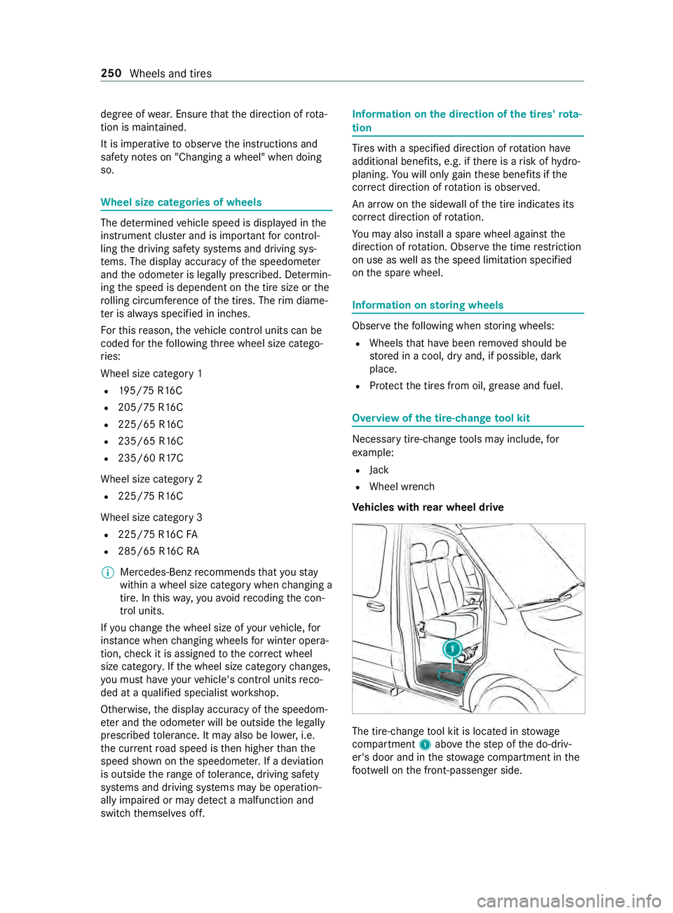
Ve hicles with rear wheel drive The tire-change
tool kit is located in stowage
compartment 1abo vethestep of the do-driv‐
er's door and in thestow age compartment in the
fo ot we ll on the front-passen ger side. 250
Wheels and tires
Page 275 of 354

Preparing
theve hicle for a wheel change Re
quirements:
R The tire-change tool kit is available.
R The vehicle is not on a slope.
R The vehicle is on solid, non-slippery and le vel
ground. #
Appl yth e parking brake. #
Movethe front wheels tothest ra ight-ahead
position. #
Vehicles with automatic transmission:
shift the transmission toposition 005D. #
Switch off the engine. #
Make sure that the engine cann otbe star ted. #
Take theve hicle tool kit from thefo ot we ll on
th e front passsenger side (/ page 229).Ve
hicles with rear wheel drive #
Take the jack and the tire-change tool kit out
of thestow age compartment (/ page 250).#
If necessar y,remo vethe hub cab. #
Assemble the lug wrench extension using the
middle rod and thero d with the lar gest diam‐
et er from theth re e-piece jack pump le ver. #
Starting with the middle rod, slide the lug
wrench extension as far as it will go onto the
lug wrench. #
Using the lug wrench, loosen the wheel nuts
or bolts on the wheel you wish tochange by
about one full turn. Do not unscr ewthe wheel
nuts or bolts comple tely. #
Raise theve hicle (/ page 251). Ra
ising theve hicle when changing a wheel &
WARNING Risk of inju ryfrom jack tip‐
ping
If yo u park a vehicle with air suspension, the
air suspension may remain activated for up to
one hour, even when the ignition is switched
off. If youth en raise theve hicle with the jac k,
th e air suspension will attem pttoadjust the
ve hicle le vel.
The jack may tip. #
Press the Service button on the air sus‐
pension remo tecontrol before raising
th eve hicle.
This pr events au tomatic readjustment
of theve hicle le vel and pr events it from
being raised or lo wered manually. &
WARNING Risk of inju ryfrom incor rect
positioning of the jack
If yo u do not position the jack cor rectly at the
appropriate jacking point of theve hicle, the
jack could tip wi th theve hicle raised. #
Only position the jack at the appropriate
jacking point of theve hicle. The base of
th e jack must be positioned vertically
under the jacking point of theve hicle. &
WARNING Risk of inju ryfrom vehicle tip‐
ping
On slopes, the jack could tip with theve hicle
ra ised. #
Neverch ange a wheel on a slope. #
Consult a qualified specialist workshop. *
NO
TEVehicle damage from the jack If
yo u do not position the jack cor rectly at the
appropriate jack support point of theve hicle,
th e jack could tip over with theve hicle raised. #
The jack is designed exclusively for
jacking up theve hicle at the jack sup‐
port points. Re
quirements:
R There are no persons in theve hicle.
R The vehicle is prepared forch anging a wheel
(/ page 251). Wheels and tires
251
Page 278 of 354
&
WARNING Risk of inju ryfrom tightening
wheel bolts and nuts
If yo u tighten the wheel bolts or wheel nuts
when theve hicle is raised, the jack could tip. #
Only tighten wheel bolts or wheel nuts
when theve hicle is on the ground. #
Obser vethe information on thech oice of
tires (/ page248). #
For saf etyre asons, only use wheel bolts or
wheel nuts which ha vebeen appr ovedby
Mercedes-Benz and forth e wheel in question.
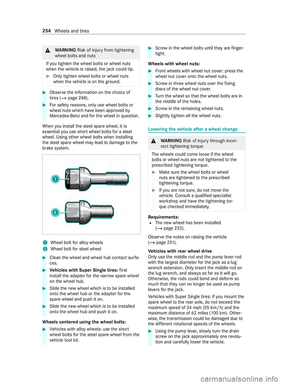
When you ins tallth esteel spare wheel, it is
essential you use short wheel bolts for a steel
wheel. Using other wheel bolts when ins talling
th esteel spare wheel may lead todamage tothe
brake sy stem. 1
Wheel bolt for alloy wheels
2 Wheel bolt forst eel wheel #
Clean the wheel and wheel hub contact sur fa‐
ces. #
Vehicles with Super Single tires: first
ins tallth e adap terfo rth e nar row spare wheel
on the wheel hub. #
Slide the new wheel which is tobe ins talled
onto the wheel hub or the adap terfo rthe
spare wheel and push it on. #
Slide the new wheel which is tobe ins talled
onto the wheel hub and push it on.
Wheels centered using the wheel bolts: #
Vehicles with alloy wheels: use the short
wheel bolts forth esteel spare wheel from the
ve hicle tool kit. #
Screw inthe wheel bolts until they are finger-
tight.
Wheels with wheel nuts: #
Front wheels with wheel nut co ver:press the
wheel nut co ver onto the wheel nuts. #
Screw inthre e wheel nuts overth efixing
discs of the wheel nut co ver. #
Turn the wheel so that the wheel bolts are in
th e middle of the holes. #
Screw inthere maining wheel nuts. #
Slightly tighten all the wheel nuts. Lo
weri ngtheve hicle af ter a wheel change &
WARNING Risk of inju rythro ugh incor‐
re ct tigh tening torque
The wheels could come loose if the wheel
bolts or wheel nuts are not tightened tothe
prescribed tightening torque. #
Makesure the wheel bolts or wheel
nuts are tightened tothe prescribed
tightening torque. #
Ifyo u are not sure, do not mo vethe
ve hicle. Consult a qualified specialist
wo rkshop and ha vethe tightening tor‐
qu ech ecked immediately. Re
quirements:
R The new wheel has been ins talled
(/ page 253).
Obser vethe no tes on raising theve hicle
(/ page 251).
Ve hicles with rear wheel drive
Only use the middle rod and the pump le verrod
with the largest diame terfo rth e jack as a lug
wrench extension. Only inse rtthe middle rod on
th e lug wrench, and alw ays as far as it will go.
Otherwise, thero ds could bend and deform so
much that they can no longer be used as pu mp
le ve rs forth e jac k.
Ve hicles with Super Single tires: if you mount the
spare wheel tothere ar axle, do not exceed the
maximum speed of 34 mph (55 km/h) and the
maximum dis tance of 62 miles (100 km). Other‐
wise, the transmission could be damaged due to
th e dif fere nt rotational speeds of the wheels. #
Using the pump le ver,slowly turn the drain
scr ew onthe jack appr oximately one revo lu‐
tion and carefully lo werth eve hicle. 254
Wheels and tires
Page 281 of 354
#
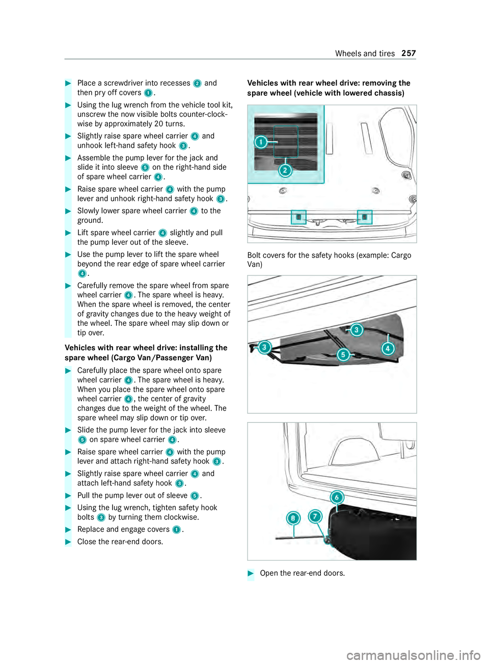
Place a scr ewdriver into recesses 2and
th en pry off co vers 1 . #
Using the lug wrench from theve hicle tool kit,
unscr ewthe now visible bolts counter-clock‐
wise byappr oximately 20 turns. #
Slightly raise spare wheel car rier 4 and
unhook left-hand saf ety hook 3. #
Assemble the pump le verfo rth e jack and
slide it into slee ve5 ontheright-hand side
of spare wheel car rier 4. #
Raise spare wheel car rier 4 with the pump
le ve r and unhook right-hand saf ety hook 3. #
Slowly lo wer spare wheel car rier 4 tothe
ground. #
Lift spare wheel car rier 4 slightly and pull
th e pump le ver out of the slee ve. #
Use the pump le verto lift the spare wheel
be yond there ar edge of spare wheel car rier
4. #
Carefully remo vethe spare wheel from spare
wheel car rier 4. The spare wheel is heavy.
When the spare wheel is remo ved, the center
of gr avity changes due tothe heavy weight of
th e wheel. The spare wheel may slip down or
tip ove r.
Ve hicles with rear wheel drive: installing the
spare wheel (Cargo Van/Passenger Van) #
Carefully place the spare wheel onto spare
wheel car rier 4. The spare wheel is heavy.
When you place the spare wheel onto spare
wheel car rier 4, the center of gravity
ch anges due tothewe ight of the wheel. The
spare wheel may slip down or tip over. #
Slide the pump le verfo rth e jack into slee ve
5 on spare wheel car rier 4. #
Raise spare wheel car rier 4 with the pump
le ve r and attach right-hand saf ety hook 3. #
Slight lyraise spare wheel car rier 4 and
attach left-hand saf ety hook 3. #
Pull the pump le ver out of slee ve5 . #
Using the lug wrench, tighten saf ety hook
bolts 3byturning them clockwise. #
Replace and engage co vers 1 . #
Close there ar-end doors. Ve
hicles with rear wheel drive: removing the
spare wheel (vehicle with lo weredch assis) Bolt co
vers forth e saf ety hoo ks(exa mp le: Cargo
Va n) #
Open there ar-end doors. Wheels and tires
257
Page 282 of 354
#
Place a scr ewdriver into recesses 2and
th en pry off co vers 1 . #
Using the lug wrench from theve hicle tool kit,
unscr ewthe now visible bolts counter-clock‐
wise byappr oximately 20 turns. #
Slightly raise spare wheel car rier 4 and
unhook left-hand saf ety hook 3. #
Assemble the pump le verfo rth e jack and
slide it into slee ve5 ontheright-hand side
of spare wheel car rier 4. #
Raise the spare wheel car rier with the pump
le ve r and unhook right-hand saf ety hook 3. #
Position loop 7ofextraction device 6on
th e spare wheel so that you will later be able
to attach lug wrench 8. #
Prepare the jac k. #
Place the jack beneath the cor responding
jack support point. #
Movethe pump le ver up and down until the
tire is raised a maximum of 1.18 in (3 cm) off
th e ground. #
Hook lug wrench 8into loop 7ofextrac‐
tion device 6onthe spare wheel. #
Carefully remo vethe spare wheel from spare
wheel car rier 4. The spare wheel is heavy.
When the spare wheel is remo ved, the center
of gr avity changes due tothe heavy weight of
th e wheel. The spare wheel may slip down or
tip ove r. #
Remo vethe spare wheel extraction device
and store it in a safe place. You can now
ins tallth e spare wheel to yourvehicle. #
Lowe rth eve hicle.
Ve hicles with rear wheel drive: installing the
spare wheel (vehicle with lo weredch assis)
% In
theeve nt of a flat tire, you may store the
defective wheel inside theve hicle only. An
intact wheel may be stored in the spare
wheel car rier only when theve hicle is unla‐
den. A laden vehicle must firs t be raised. #
Carefully place the spare wheel onto spare
wheel car rier 4. The spare wheel is heavy.
When you place the spare wheel onto spare
wheel car rier 4, the center of gravity
ch anges due tothewe ight of the wheel. The
spare wheel may slip down or tip over. #
Slide the pump le verfo rth e jack into slee ve
5 on spare wheel car rier 4. #
Raise spare wheel car rier 4 with the pump
le ve r and attach right-hand saf ety hook 3. #
Slight lyraise spare wheel car rier 4 and
attach left-hand saf ety hook 3. #
Pull the pump le ver out of slee ve5 . #
Using the lug wrench, tighten saf ety hook
bolts 3byturning them clockwise. #
Replace and engage co vers 1 . #
Close there ar-end doors.
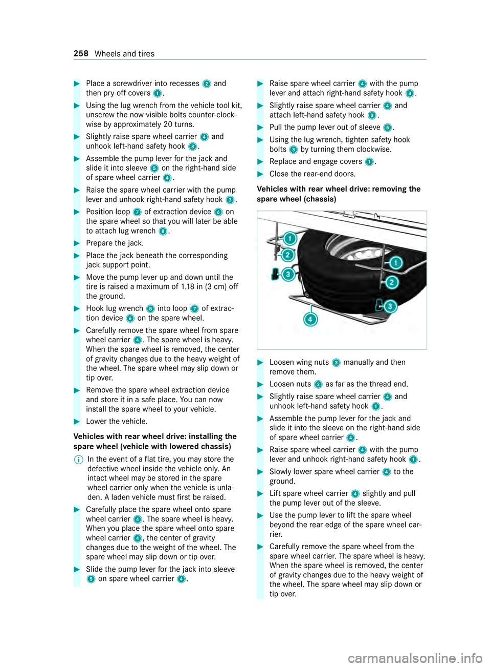
Ve hicles with rear wheel drive: removing the
spare wheel (chassis) #
Loosen wing nuts 3manually and then
re mo vethem. #
Loosen nuts 2asfar as theth re ad end. #
Slightly raise spare wheel car rier 4 and
unhook left-hand saf ety hook 1. #
Assemble the pump le verfo rth e jack and
slide it into the slee veon theright-hand side
of spare wheel car rier 4. #
Raise spare wheel car rier 4 with the pump
le ve r and unhook right-hand saf ety hook 1. #
Slowly lo wer spare wheel car rier 4 tothe
ground. #
Lift spare wheel car rier 4 slightly and pull
th e pump le ver out of the slee ve. #
Use the pump le verto lift the spare wheel
be yond there ar edge of the spare wheel car‐
ri er. #
Carefully remo vethe spare wheel from the
spare wheel car rier. The spare wheel is heavy.
When the spare wheel is remo ved, the center
of gr avity changes due tothe heavy weight of
th e wheel. The spare wheel may slip down or
tip ove r. 258
Wheels and tires
Page 293 of 354

cases, oil of
the type in the engine is not availa‐
ble, use ano ther appr oved mineral or synthetic
engine oil.
Ve hicles with a diesel engine: ifth e grade is
not available, you may also refill with engine oils
acco rding toMB-F reigabe or MB-Appr oval 228.5,
229.3 or 229.5. The top-up quantity is then limi‐
te dto maximum 1.1 US qt (1.0 liter).
Yo u must then ha vean oil change car ried out at
th e earliest possible opportunit y.
Ve hicles with a gasoline engine: ifth e grade is
not available, you may refill with engine oils
acco rding toMB-F reigabe or MB-Appr oval 229.3
or AC EA A3/B4. The top-up quantity is then limi‐
te dto maximum 1.1 US qt (1.0 liter).
Yo u must then ha vean oil change car ried out at
th e earliest possible opportunit y.
Engine oils are di stinguished by:
R engine oil brand
R grade (MB-F reigabe or MB-Appr oval)
R SAE classi fication (viscosity)
Oil change inter val
The on-board computer automatically sho wsthe
date of the next oil change as an event messa ge
on the displa y.
Mercedes-Benz recommends having the oil
ch anged at a qualified specialist workshop.
Engine oil capacities Engine
Engine oil
M2 74 around11.2 qt
(10.5 li ters)
OM642 around13.2 qt
(12.5 li ters)
OM651 (rear wheel
drive) around
12qt
(1 1. 5 liters) Information on oil consum
ption
Depending on the driving style, theve hicle con‐
sumes a maximum of 1.1 US qt (1.0 liter) of
engine oil per 620 miles (1000 km).
In thefo llowing cases, oil consum ption may also
exc eed this limit:
R theve hicle is ne w.
R you use theve hicle mostly under arduous
conditions.
R you drive frequently at a high engine speed. Re
gular maintenance is a prerequisite forfa vo ra‐
ble consum ption figures. You can on lyassess the
oil consum ption af ter a long journe y.Check the
oil le vel in the engine regularly, e.g. weekly or
ev ery time youre fuel. Note
s on brake fluid Obser
vethe no tes on operating fluids
(/ page 263). &
WARNING Risk of an accident due to
va por poc kets form ing in the brake sys‐
tem
The brake fluid con stantly absorbs moisture
from the air. This lo wersthe boiling point of
th e brake fluid. If the boiling point is too lo w,
va por poc kets may form inthe brake sy stem
when the brakes are applied hard.
This causes the braking ef fect to be impaired. #
Have the brake fluid rene we d at the
specified inter vals. *
NO
TEDama getopaint, plastic or rubber
by brake fluid There is a
risk of damage toproperty if brake
fl uid comes into con tact wi thpaint, plastic or
ru bber. #
If paint, plastic or rubber comes into
con tact wi thbrake fluid, rinse wi th
wate r immediatel y. Obser
vethe no tes on paintwork/matte finish
paintwork care (/ page 211).
Ha ve the brake fluid replaced regular lyat a quali‐
fi ed specialist workshop.
Only use brake fluid appr ovedby Mercedes-Benz
in accordance with MB-F reigabe or MB-Appr oval
33 1.0.
Fu rther information on brake fluid:
R inthe MB Specifications for operating fluids
at http://be vo.mercedes-benz.com
R at a qualified specialist workshop Coolant
Note
s on coolant
Obser vethe no tes on operating fluids
(/ page 263). Te
ch nical da ta269
Page 315 of 354

Display messages
Possible causes/consequences and 0050 0050Solutions #
Check the tires.
0077 Check Tires *T
he pressure in one or more tires has fallen significantl y.The wheel
position is shown. &
WARNING Risk of an accident due toinsuf ficient tire pres‐
sure
Ti re pressures that are too low pose thefo llowing hazards:
R The tires may bur st, especially as the load and vehicle speed
increase.
R The tires may wearexc essively and/or une venly, which may
greatly impair tire traction.
R The driving characteristics, as well as steering and braking,
may be greatly impaired.
Yo u could then lose cont rol of theve hicle. #
Obser vethere commended tire pressu re. #
Adjust the tire pressure if necessar y. #
Stop in accordance with the tra ffic conditions. #
Check the tire pressure (/ page 234) andthe tires.
0077 Please Correct Tire Pres-
sure *T
he pressure in at least one tire is too low or the pressures of the
individual tires deviate too much from each other. #
Check the tire pressure, and add air if necessar y. #
When the tire pressure has been set cor rectl y,re-sta rt the tire
pressure monitor (/ page240).
Tire Pressure Monitor
Inoperative *T
he tire pressure monitor is malfunctioning. #
Visit a qualified specialist workshop. Key
Display messages
Possible causes/consequences and 0050 0050Solutions
00AF
Don't Forget Your Key *T
his message reminds you not tolea veyour key in theve hicle. #
Take theke y with you when youget out of theve hicle.
00AF Place the Key in the
Marked Space See Oper-
ator's Manual *K
eydetection is malfunctioning. #
Change theke y's position in theve hicle. #
Start theve hicle with theke y in the slot(/ page104).
00AF *T
hekey is not de tected and may no longer be in theve hicle.
The key is no lon ger in theve hicle and you swit chthe engine off:
R You can no lon gerst art the engine. Display messages and
warning and indicator lamps 291