Page 117 of 673

Easy entry and
exitfeature Using
the easy entry and exitfeature &
WARNING Risk of accident when pulling
aw ay during the adjustment process of
th e easy exitfeature
‑ If you pull away while the easy entry and
ex itfeature is making adjustments, you could
lose cont rol of theve hicle. #
Alw ayswa it until the adjustment proc‐
ess is comple tebefore pulling away. &
WARNING Risk of becoming trapped
while adjusting the easy entry andexit
fe ature
When the easy entry andexitfeature adjusts
th esteering wheel and the driver's seat, you
and other vehicle occupants – particular ly
ch ildren – could become trapped. #
During the adjustment process forthe
easy entry andexitfeature, make sure
th at no one has any body parts in the sweep of
thesteering wheel or the driv‐
er's seat.
If th ere is a risk of becoming trapped bythe
st eering wheel: #
Movethe adjustment le ver of thesteer‐
ing wheel.
The adjustment process is stopped.
If th ere is a risk of becoming trapped bythe
driver's seat: #
Press the seat adjustment switch.
The adjustment process is stopped. #
Never lea vechildren unat tended in the
ve hicle. #
When leaving theve hicle, alw aysta ke
th eke y with you and lock theve hicle.
This also applies tothe digital vehicle
ke y if the "Digital Vehicle Key" function
is activated via Mercedes me connect. Ve
hicles with memory function: you can stop
th e adjustment process bypressing one of the
memory function position switches. &
WARNING Risk of becoming trapped
du ring acti vation of the easy entry and
ex itfeature bychildren
If ch ildren activate the easy entry andexit
fe ature, they can become trapped, pa rticu‐
lar lywhen unat tended. #
Never lea vechildren unat tended in the
ve hicle. #
When leaving theve hicle, alw aysta ke
th eke y with you and lock theve hicle. This also applies
tothe Digital Vehicle Key if the
"Digital Vehicle Key" function is activated via
Mercedes me connect.
If th e easy entry andexitfeature is active, the
st eering wheel will mo veupwards and the driv‐
er's seat will mo veback in thefo llowing situa‐
tions:
R you swit chthe ignition off with the driver's
door open
R you open the driver's door with the ignition
switched off 11 4
Seats and stowing
Page 118 of 673

%
The steering wheel will mo veupwards on lyif
it is not already as high as it will go. The driv‐
er's seat will mo vebackwards only if it is not
already in there armost position.
The steering wheel and the driver's seat will
mo veback tothe last drive position in thefo l‐
lowing cases:
R you swit chthe po wer supp lyor the ignition
on when the driver's door is closed
R you close the driver's door with the ignition
switched on
The last drive position will be stored when:
R you swit chthe ignition off
R vehicles with memory function: you call
up the seat settings via the memory function.
R vehicles with memory function: you sa ve
th e seat settings via the memory function.
Ve hicles with memory function: press one of
th e memory function sa ved position buttons to
st op the adjustment process. Operating
the memory function &
WARNING Risk of an accident if the
memory function is used while driving
If yo u use the memory function on the driv‐
er's side while driving, you could lose cont rol
of theve hicle as a result of the adjustments
being made. #
Only use the memory function on the
driver's side when theve hicle is station‐
ar y. &
WARNING Risk of entrapment when set‐
ting the seat with the memory function
When the memory function adjusts the seat
or steering wheel, you and other vehicle
occupants – particularly children – could
become trapped. #
During the setting procedure of the
memory function, ensure that no body
parts are in the sweep of the seat or
th esteering wheel. #
If somebody becomes trapped, immedi‐
ately release the memory function posi‐
tion button.
The adjustment process is stopped. &
WARNING Risk of entrapment if the
memory function is activated bychildren
Children could become trapped if they acti‐
va te the memory function, particularly when
unattended. #
Never lea vechildren unat tended in the
ve hicle. #
When leaving theve hicle, alw aysta ke
th eke y with you and lock theve hicle. This also applies
tothe Digital Vehicle Key if the
"Digital Vehicle Key" function is activated via
Mercedes me connect.
The memory function can be used when the igni‐
tion is switched off.
St oring
Seat adjustments for up tothre e people can be
st ored and called up using the memory function. Seats and
stowing 11 5
Page 121 of 673
3
Stow age compartment in the front cent re
console wi tha USB connection and charging
module for wireless charging of a mobile
phone (not available in all countries)
4 Glovecompa rtment
Locking/unlo cking thegl ove compa rtment #
Turn the emer gency key a quarter turn clock‐
wise 2(to lock) or anti-clockwise 1(to
unlock).
Opening the spectacles compa rtment #
Press button 1. Opening the
stowage compa rtment in the
re ar armrest #
Press there lease cat ch1 and swing the
co ver of the armrest upwards. 11 8
Seats and stowing
Page 122 of 673

Through-loading
feature in there ar ben ch
seat Fo
lding there ar seat backrest forw ards &
WARNING Risk of inju ryifth ere ar
ben chseat/rear seat and seat backrest
are not engaged
If th ere ar ben chseat/rear seat and seat
backrest are not engaged they could fold for‐
wa rds, e.g. when braking suddenly or in the
ev ent of an accident.
R Ifth is is the case, theve hicle occupant
wo uld be forc ed into the seat belt bythe
re ar ben chseat/rear seat or bythe seat
backrest. The seat belt cann otprotect as
intended and could result in additional
injur y.
R Objects or loads in the boot/load com‐
partment cann otbe restra ined bythe
seat backrest. #
Make sure that the seat backrest and
th ere ar ben chseat/rear seat are
engaged before everytrip. If
th e left and right seat backrests are not
engaged and loc ked in place, this will be shown
on the multifunction display of the instrument
clus ter.A wa rning tone will also sound.
If th e cent reseat backrest is not engaged and
loc ked, there d lock verification indicator will be
visible.
The centre and ou ter seat backrests can be fol‐
ded forw ards separatel y.
The outer seat backrests are unloc ked elect ri‐
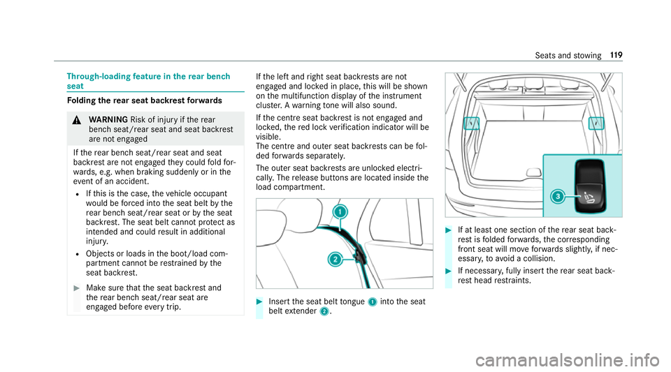
cally. The release buttons are located inside the
load compartment. #
Insert the seat belt tongue 1into the seat
belt extender 2. #
If at least one section of there ar seat back‐
re st isfolded forw ards, the cor responding
front seat will mo veforw ards slightl y,if nec‐
essar y,to avoid a collision. #
If necessar y,fully insert there ar seat back‐
re st head restra ints. Seats and
stowing 11 9
Page 124 of 673
Centre seat backres
t:ifth e seat backrest is
not engaged and loc ked, there d lock verifi‐
cation indicator 2will be visible.
Lo cking there lease catch of the centre rear
seat backrest
Re quirements:
R The left and centre seat backrests are
engaged and joined toge ther.
Lock the cent reseat backrest release cat chif
yo uwa nttosecure the load compartment from
unauthorised access. The cent reseat backrest
can then be folded forw ards on lytoge ther with
th e left seat backrest. #
Foldthe cent reand left seat backrests for‐
wa rds. #
Tolock: slidethe catch 1upwards.
The release cat chofthe cent reseat backrest
will be loc ked. #
Tounlo ck:slide the catch 1down wards. Ad
justing the angle of the rear seat backr‐
ests (cargo position)
To enlar gethe load compartment, you can adjust
th e seat backrests so that they are ten degrees
st eeper (cargo position). #
Foldthe seat backrest forw ards
(/ page 119). Seats and
stowing 121
Page 134 of 673
#
Fold out hook 2onthe underside of the
load compartment floor. #
Attach hook 2to to p seal 3ofthe load
compartment. #
Toclose: Remo vehook 2from top seal 3
of the load compartment. #
Secure hook 2tothe brac ket on the under‐
side of the load compartment floor. #
Foldthe load compartment floor down. Locking and unlocking
the load compa rt‐
ment floor #
Turn the emer gency key a quarter turn clock‐
wise 2(to lock) or anti-clockwise 1(to
unlock). Seats and
stowing 131
Page 142 of 673

Wire
lesscharging of a mobile phone Re
quirements:
R The mobile phone is suitable for wireless
ch arging. You can find a li stof compatible
mobile phones at:
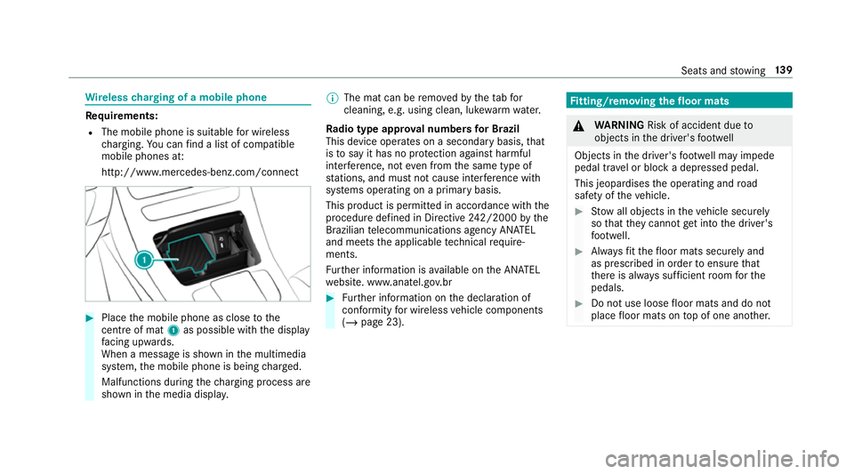
http://www.mercedes-benz.com/connect #
Place the mobile phone as close tothe
centre of mat 1as possible wi th the display
fa cing up wards.
When a message is shown in the multimedia
sy stem, the mobile phone is being charge d.
Malfunctions during thech arging process are
shown in the media displa y. %
The mat can be remo vedby theta bfor
cleaning, e.g. using clean, lu kewa rm wate r.
Ra dio type appr oval numbers for Brazil
This device operates on a secondary basis, that
is to say it has no pr otection against harmful
inter fere nce, not even from the same type of
st ations, and must not cause inter fere nce wi th
sy stems operating on a primary basis.
This product is permitted in accordance with the
procedure defined in Directive 242/2000 bythe
Brazilian telecommunications agency AN ATEL
and meets the applicable tech nical requ ire‐
ments.
Fu rther information is available on the AN ATEL
we bsite. www.anatel.go v.br #
Further information on the declaration of
confo rmity for wireless vehicle components
(/ page 23). Fi
tting/ removing the floormats &
WARNING Risk of accident due to
objects in the driver's foot we ll
Objects in the driver's foot we ll may impede
pedal tr avel or block a depressed pedal.
This jeopardises the operating and road
saf ety of theve hicle. #
Stow all objects in theve hicle securely
so that they cannot getinto the driver's
fo ot we ll. #
Alw aysfit th efloor mats securely and
as prescribed in order toensure that
th ere is alw ays suf ficient room forthe
pedals. #
Do not use loose floor mats and do not
place floor mats on top of one ano ther. Seats and
stowing 13 9
Page 156 of 673
#
Hold the wiper arm with one hand. With the
ot her hand, turn the wiper blade in the direc‐
tion of ar row1away from the wiper arm as
fa r as it will go. #
Slide catch 2inthe direction of ar row 3
until it engages in there mo val position. #
Remo vethe wiper blade from the wiper arm
in the direction of ar row4. Fi
tting the wiper blades #
Inse rtthe new wiper blade into the wiper
arm in the direction of ar row1. #
Slide catch 2inthe direction of ar row 3
until it engages in the locking position. #
Make sure that the wiper blade is seated cor‐
re ctly. #
Foldthe wiper arms back onto the wind‐
screen. #
Switch on the ignition. #
Press theî button on the combination
switch (/ page151).
The wiper arms will mo veinto the original
position.
Maintenance display Light and sight
15 3