2019 MERCEDES-BENZ GLC SUV load capacity
[x] Cancel search: load capacityPage 282 of 673
Un
coupling a trailer &
WARNING Risk of being crushed and
becoming trapped when uncoupling a
trailer
When uncoupling a trailer wi than engaged
ine rtia-activated brake, your hand may
become trapped between theve hicle and the
trailer dr awbar. #
Do not uncouple trailers with an
engaged overrun brake. *
NO
TEDama gewhen uncoupling in a
st ate of overrun Uncou
pling in a state of overru n can dama ge
th eve hicle. #
Do not uncouple trailers with an
engaged overrun brake. &
WARNING Risk of becoming trapped
when disconnecting the trailer cable
Ve hicles with le vel control sy stem: The
ve hicle may lo wer when the trailer cable is
disconnected.
This could result in you or other people
becoming trapped if your or their limbs are
between theve hicle body and the tyres or
underneath theve hicle. #
Make sure that nobody is unde rneath
th eve hicle or in the immediate vicinity
of the wheel ar ches when you discon‐
nect the trailer cable. *
NO
TEDama getothere ar bumper from
ins talling adap ter cables or adapte r plugs The
following parts could be damaged when
swinging the ball neck fully electrically:
R bumper
R adap ter cable
R adapte r plug #
Alw aysre mo vethe adap ter cable or
adapte r plug before swinging the ball
neck fully electrically. #
Secure the trailer against rolling away. #
Disconnect the electrical connection
between theve hicle and the trailer. #
Uncouple the trailer. #
Place the co ver on the ball head. Bicycle
rackfunction &
WARNING Risk of an accident when
using the bicycle rack incor rectly
The bicycle rack may become de tach ed from
th eve hicle in thefo llowing cases:
R the permissible load capacity of the
trailer hitch is exceeded.
R the bicycle rack is used incor rectl y.
R the bicycle rack is secured tothe ball
neck beneath the ball head. Driving and parking
279
Page 283 of 673
Obser
vethefo llowing foryo ur ow n sa fety
and that of other road users:
R always adhere tothe permissible load
capacity of the trailer hitch.
R only use the bicycle rack totranspo rt
bicycles.
R always mount the bicycle rack properly by
attaching tothe ball head and the ball
neck guide pin, if possible.
R when transporting four bic ycles, alw ays
use bic ycle rack s which ha veadditional
suppo rton the ball neck guide pin.
R only use bicycle rack s appr ovedby
Mercedes-Benz.
R always obser vethe bicycle rack operating
instructions. *
NO
TEDama geto, or cra cks on, the
trailer hitch due tounsuitable bic ycle
ra ck s or bicycle rack s being used incor‐
re ctly #
use only bicycle rack s appr ovedby
Mercedes-Benz. Tr
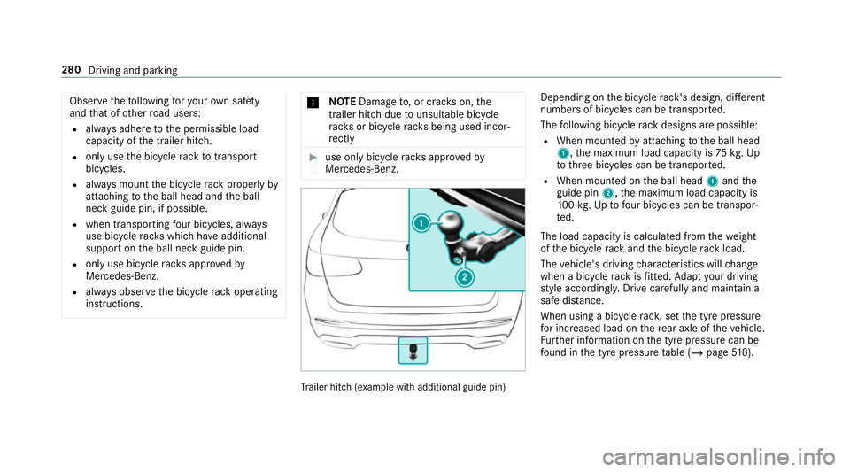
ailer hit ch(examp le with additional guide pin) Depending on
the bicycle rack 's design, dif fere nt
numbe rsof bicycles can be transpor ted.
The following bicycle rack designs are possible:
R When mounted byattaching tothe ball head
1, the maximum load capacity is 75kg.Up
to thre e bicycles can be transpor ted.
R When mounted on the ball head 1and the
guide pin 2,the maximum load capacity is
10 0kg .Up tofour bic ycles can be transpor‐
te d.
The load capacity is calculated from thewe ight
of the bicycle rack and the bicycle rack load.
The vehicle's driving characteristics will change
when a bicycle rack isfitted. Adapt your driving
st yle according ly. Drive carefully and maintain a
sa fe dis tance.
When using a bicycle rack , set the tyre pressure
fo r increased load on there ar axle of theve hicle.
Fu rther information on the tyre pressure can be
fo und in the tyre pressure table (/ page518). 280
Driving and pa rking
Page 529 of 673
#
Select Yes. #
Toconfirm restart, press Touch Control on
th e left-hand side of thesteering wheel.
The Run Flat Indicator restarted message is
shown in the multifunction displa y.
Be sure toalso obse rveth efo llowing fur ther
re lated subjects:
R Notes on tyre pressure (/ page517) Wheel
change Note
s on selecting, fitting and replacing
tyres Mercedes
-AMG vehicles: observeth e no tes in
th e Supplement. Otherwise, you may failto rec‐
ognise dangers.
Yo u can ask for information rega rding permit ted
wheel/tyre combinations at a Mercedes-Benz
Service Cent re. &
WARNING Risk of accident due toincor‐
re ct dimensions of wheels and tyres
If wheels and tyres of the wrong size are
used, the wheel brakes or wheel suspension
components may become damaged. #
Alw aysre place wheels and tyres with
th ose that fulfil the specifications of the
original part.
When replacing wheels, make sure tofit the
cor rect:
R Designation
R Type
When replacing tyres, make sure tofit the
cor rect:
R Designation
R Manufactu rer
R Type &
WARNING Risk of inju rythro ugh exceed‐
ing the specified tyre load-bearing capa‐
city or the permissible speed rating
Exceeding the specified tyre load-bearing
capacity or the permissible speed rating may
lead totyre dama geand tothe tyres bur st‐
ing. #
Therefore, only use tyre types and sizes
appr ovedfo ryo ur vehicle model. #
Obser vethe tyre load-bearing capacity
ra ting and speed rating requ iredfor
yo ur vehicle. *
NO
TEVehicle and tyre damage thro ugh
tyre types and sizes that ha venot been
appr oved Fo
r saf etyre asons, on lyuse tyres, wheels
and accessories which ha vebeen specially
appr ovedby Mercedes-Benz foryo ur vehicle. 526
Wheels and tyres
Page 533 of 673
Mercedes-AMG
vehicles: observeth e no tes in
th e Supplement. Otherwise, you may failto rec‐
ognise dangers.
Apa rtfrom some countr y-specific variants, vehi‐
cles are not equipped with a tyre-change tool kit.
Fo r more information on which tyre-changing
to ol kits are required and appr oved for per form‐
ing a wheel change on your vehicle, consult a
qu alified specialist workshop.
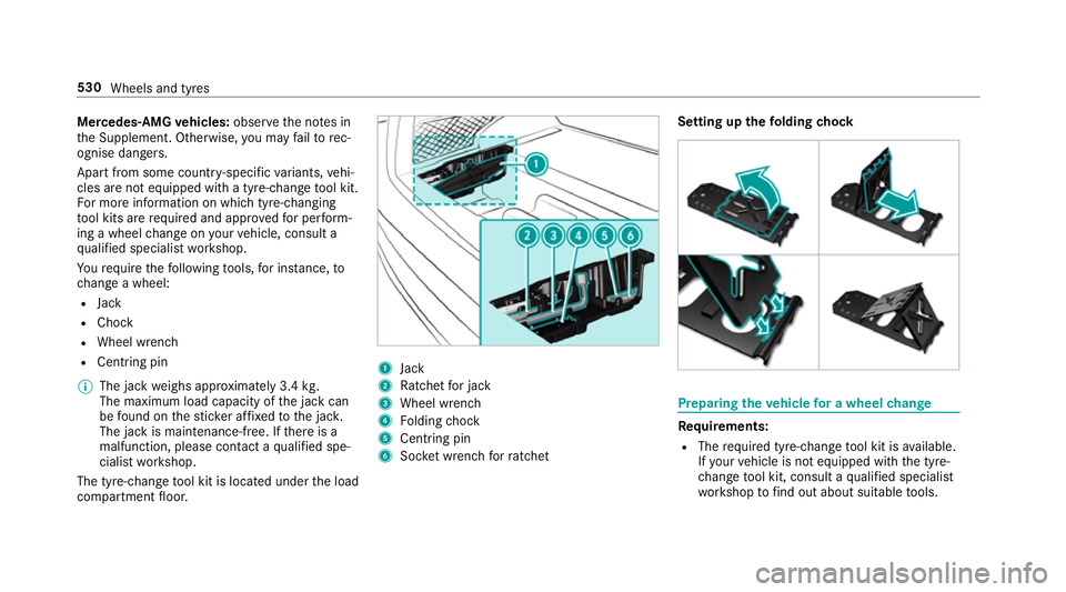
Yo ure qu ire thefo llowing tools, for ins tance, to
ch ange a wheel:
R Jack
R Chock
R Wheel wrench
R Cent ring pin
% The jack weighs appr oximately 3.4 kg.
The maximum load capacity of the jack can
be found on thest icke r af fixe dto the jac k.
The jack is maintenance-free. If there is a
malfunction, please conta ct aqualified spe‐
cialist workshop.
The tyre-change tool kit is located under the load
compartment floor. 1
Jack
2 Ratchet for jack
3 Wheel wrench
4 Folding chock
5 Centring pin
6 Socket wrench forra tchet Setting up the
folding chock Prepa
ring theve hicle for a wheel change Re
quirements:
R The requ ired tyre-change tool kit is available.
If yo ur vehicle is not equipped with the tyre-
ch ange tool kit, consult a qualified specialist
wo rkshop tofind out about suitable tools. 530
Wheels and tyres
Page 555 of 673
The
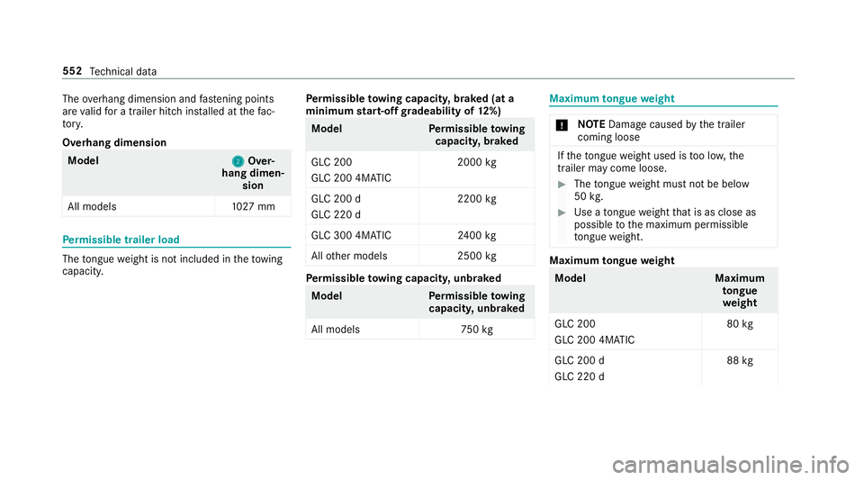
overhang dimension and fastening points
are valid for a trailer hitch ins talled at thefa c‐
to ry.
Overhang dimension Model
2 2Over‐
hang dimen‐ sion
All models 1027 mm Pe
rm issible trailer load The
tongue weight is not included in theto wing
capacity. Pe
rm issible towing capacit y,braked (at a
minimum start-off gradeability of 12%) Model
Perm issible towing
capacit y,braked
GLC 200
GLC 200 4MATIC 2000
kg
GLC 200 d
GLC 220 d 2200
kg
GLC 300 4MATIC 2400 kg
All other models 2500kg Pe
rm issible towing capacit y,unbraked Model
Perm issible towing
capacit y,unbraked
All model s7 50kg Maximum
tongue weight *
NO
TEDama gecaused bythe trailer
coming loose If
th eto ngue weight used is too lo w,the
trailer may come loose. #
The tongue weight must not be below
50 kg. #
Use a tongue weight that is as close as
possible tothe maximum permissible
to ngue weight. Maximum
tongue weight Model
Maximum
to ngue
we ight
GLC 200
GLC 200 4MATIC 80
kg
GLC 200 d
GLC 220 d 88
kg 552
Tech nical da ta
Page 663 of 673
Sy
stem settings
Ac tivating/deactivating PIN pr otec‐
tion ...................................................... 359
Re set function (multimedia sy stem) ....3 62
Setting the dis tance unit ..................... 358
Setting the time and date automati‐
cally ..................................................... 354
Setting the time zone .......................... 354
Setting the time/date form at .............. 354
Swit ching transmission of theve hicle
position on/off .................................... 355
Sy stem settings
see Blue tooth®
see Data import/export
see Language
see Software update
see Wi-Fi T
Ta ilgate ...................................................... .83
Closing .................................................. 84
HANDS-FREE ACCESS .......................... .86
Limiting the opening angle .................... 88
Opening .................................................83
Opening dimensions ............................5 49Un
locking (emer gency key) .................. .88
Ta ilpipes (Care) ........................................ 489
Ta ke -back of end-of-life vehicles .............. 19
Pr otection of the environment ............... 19
Ta nk content
Ad Blue ®
............................................... 545
Fu el ..................................................... 544
Re ser ve(fuel) ...................................... 544
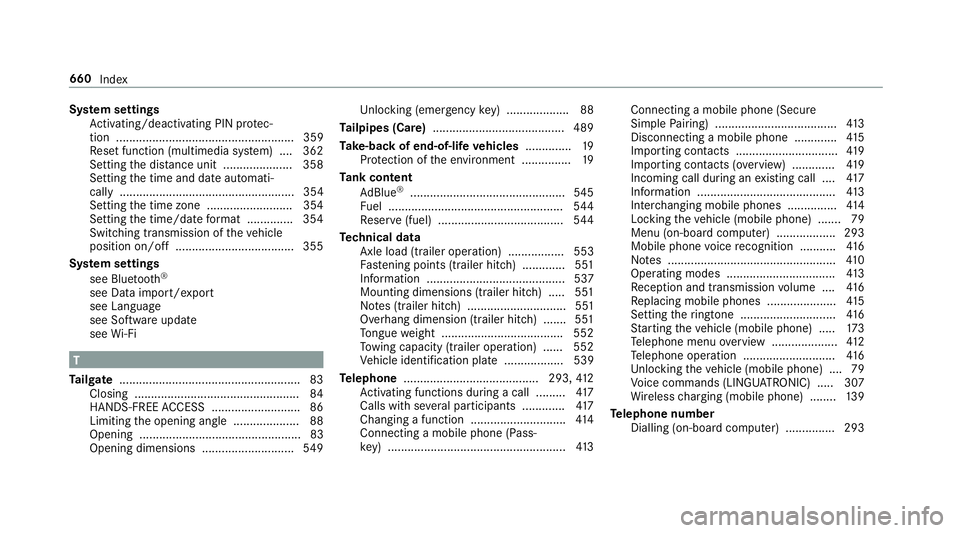
Te ch nical data
Axle load (trailer operation) ................. 553
Fa stening points (trailer hitch) .............5 51
Information .......................................... 537
Mounting dimensions (trailer hitch) ..... 551
No tes (trailer hitch) .............................. 551
Overhang dimension (trailer hitch) .......5 51
To ngue weight .................................... .552
To wing capacity (trailer operation) ...... 552
Ve hicle identification plate .................. 539
Te lephone ........................................ .293,412
Ac tivating functions du ring a call ......... 417
Calls with se veral participants ............ .417
Changing a function ............................ .414
Connecting a mobile phone (Pass‐
ke y) ...................................................... 413Connecting a mobile phone (Secure
Simple
Pairing) .................................... .413
Disconnecting a mobile phone ............ .415
Importing contacts ............................... 419
Importing contacts (o verview) ............ .419
Incoming call during an existing call .... 417
Information .......................................... 413
Inter changing mobile phones .............. .414
Locking theve hicle (mobile phone) .......79
Menu (on-board computer) .................. 293
Mobile phone voice recognition ........... 416
No tes ................................................... 41 0
Operating modes ................................. 413
Re ception and transmission volume .... 416
Re placing mobile phones .....................4 15
Setting theringtone ............................. 416
St arting theve hicle (mobile phone) ..... 173
Te lephone menu overview .................... 412
Te lephone operation ............................ 416
Un locking theve hicle (mobile phone) ....79
Vo ice commands (LINGU ATRO NIC) .....3 07
Wi reless charging (mobile phone) ........ 13 9
Te lephone number
Dialling (on-board computer) .............. .293 660
Index
Page 665 of 673
To
wing eye
Ins talling .............................................. 512
St orage location ................................... 511
To wing me thods ...................................... 507
Tr af fic announcements
Ac tivating/deactivating ...................... .462
Tr af fic information .................................. 393
Car-to-X-Communication .................... .396
Displ aying the tra ffic map .................. .394
Displ aying traf fic incidents .................. 395
Extending a Live Traf fic Information
subscription ......................................... 394
Live Traf fic Information ....................... 393
Overview ............................................. 393
Re gis tering Live Traf fic Information ..... 394
Switching on the display ......................3 96
Tr af fic map
see Map
Tr af fic Sign Assist .................................. .268
Fu nction/no tes ................................... 268
Setting .................................................2 69
Sy stem limitations ...............................2 68
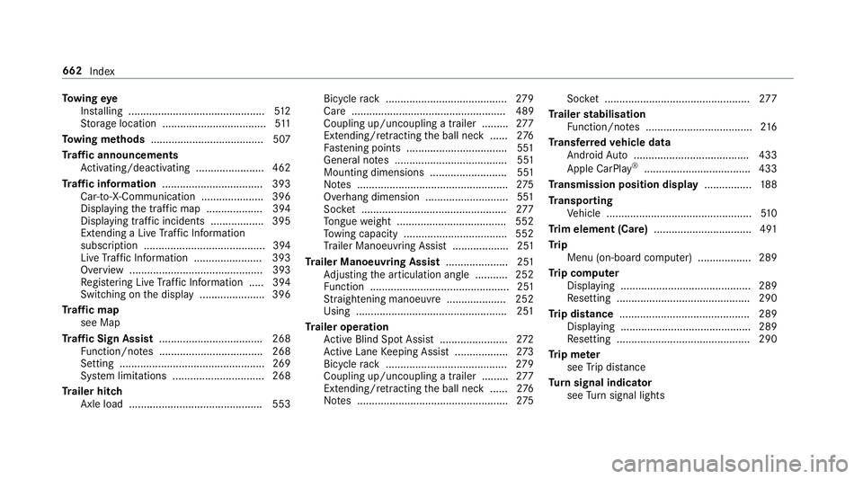
Tr ailer hitch
Axle load ............................................. 553 Bicycle
rack ......................................... 279
Care .................................................... 489
Coupling up/uncoupling a trailer ........ .277
Extending/r etra cting the ball neck ...... 276
Fa stening points ..................................5 51
Gene ral no tes ...................................... 551
Mounting dimensions .......................... 551
No tes ................................................... 275
Overhang dimension ............................5 51
Soc ket ................................................. 277
To ngue weight .................................... .552
To wing capacity .................................. .552
Tr ailer Manoeuv ring Assi st................... 251
Tr ailer Manoeuvring Assist ..................... 251
Ad justing the articulation angle ........... 252
Fu nction ............................................... 251
St raightening manoeuvre .................... 252
Using .................................................. .251
Tr ailer operation
Ac tive Blind Spot Assi st....................... 272
Ac tive Lane Keeping Assist .................. 273
Bicycle rack ......................................... 279
Coupling up/uncoupling a trailer ........ .277
Extending/r etra cting the ball neck ...... 276
No tes ................................................... 275Soc
ket ................................................. 277
Tr ailer stabilisation
Fu nction/no tes .................................... 216
Tr ansfer redve hicle data
Android Auto ....................................... 433
Apple CarPl ay®
.................................... 433
Tr ansmission position display ................188
Tr anspo rting
Ve hicle .................................................5 10
Tr im element (Care) .................................491
Tr ip
Menu (on-board computer) .................. 289
Tr ip computer
Displaying ............................................ 289
Re setting ............................................. 290
Tr ip distance ............................................ 289
Displaying ............................................ 289
Re setting ............................................. 290
Tr ip me ter
see Trip dis tance
Tu rn signal indicator
see Turn signal lights 662
Index