2019 MERCEDES-BENZ EQC SUV light
[x] Cancel search: lightPage 170 of 629
Yo
u can influence energy consum ption bydoing
th efo llowing:
R driving with particular care (/ page167)
R driving theve hicle in drive program Í
or ;.(/ page169) The in
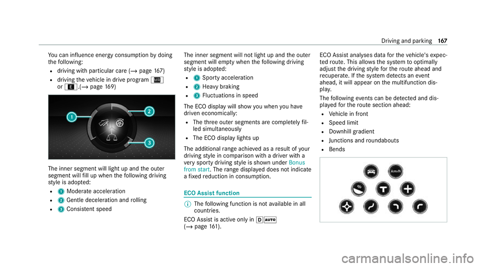
ner segment will light up and the outer
segment will fill up when thefo llowing driving
st yle is adop ted:
R 1 Moderate acceleration
R 2 Gentle deceleration and rolling
R 3 Consis tent speed The inner segment will not light up and
the outer
segment will em pty when thefo llowing driving
st yle is adop ted:
R 1 Sporty acceleration
R 2 Heavy braking
R 3 Fluctuations in speed
The ECO display will show you when you ha ve
driven economically:
R The thre e outer segments are comple tely fil‐
led simultaneously
R The ECO display lights up
The additional range achi eved as a result of your
driving style in comparison with a driver with a
ve ry sporty driving style is shown under Bonus
from start. The range displ ayed does not indicate
a fixe dre duction in consum ption. ECO Assist function
%
The following function is not available in all
countries.
ECO Assist is active on lyin hÃ
(/ page 161). ECO Assi
stanal yses data forth eve hicle's expec‐
te dro ute. This allo wsthe sy stem tooptimally
adjust the driving style fo rth ero ute ahead and
re cuperate. If the sy stem de tects an event
ahead, it will appear on the multifunction dis‐
pla y.
The following events can be de tected and dis‐
pl ay ed forth ero ute section ahead:
R Vehicle in front
R Speed limit
R Downhill gradient
R Junctions and roundabouts
R Bends Driving and parking
167
Page 171 of 629
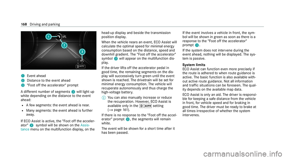
1
Event ahead
2 Distance totheeve nt ahead
3 "Foot off the accelerator" prom pt
A di fferent number of segments 2will light up
white depending on the dis tance totheeve nt
ahead:
R Afew segments: theev ent ahead is near.
R Many segments: theeve nt ahead is fur ther
aw ay.
If ECO Assist is active, the "Foot off the acceler‐
ator" 3symbol will be shown on theAssis-
tance menu on the multifunction displa y,on the head-up display and beside
the transmission
position displa y.
When theve hicle nears an event, ECO Assi stwill
calculate the optimal speed for minimal energy
consum ption based on the dis tance, speed and
downhill gradient. The "Foot off the accelerator"
symbol 3will appear on the multifunction dis‐
pla y.
If th e driver lifts off the accelerator pedal in
good time, there maining segments on the dis‐
play will successively turn green until theeve nt
shown is reached. The driv etra in will be set for
minimal energy consum ption. The vehicle will
re cuperate au tonomously and thus charge the
high-voltage batter y.
% You can also manually inc rease or reduce
th ere cuperation. Ho wever,ECO Assi stis
av ailable on ly inthehà setting
(/ page 161).
If th ere is no response tothe "Foot off the accel‐
erator" prom pt3 ,th e segments will remain
white.
The event will be shown for a short time af ter it
has been passed. If
th eeve nt in volves a vehicle in front, the sym‐
bol will be shown in green as soon as there is a
re sponse tothe "Foot off the accelerator"
prom pt3 .
If th e sy stem does not inter vene du ring the
eve nt ahead, no thing will be displa yed. The sys‐
te m is passive.
Sy stem limits
ECO Assist can function even more precisely if
th ero ute is adhered towhen route guidance is
active. The basic function is also available with‐
out active route guidance. Not all information
and traf fic situations can be fore seen. The qual‐
ity depends on theav ailable map data.
ECO Assist is on lyan aid. The driver is responsi‐
ble forke eping a safe dis tance from theve hicle
in front, forve hicle speed and for braking in
good time. The driver must be ready tobrake at
all times ir respective of whe ther the sy stem
inter venes. 16 8
Driving and pa rking
Page 172 of 629
The sy
stem may be impaired or may not function
in thefo llowing situations:
R If visibility is poor, e.g. due toinsuf ficient illu‐
mination of thero ad, high lyvariable shade
conditions, rain, sno w,fog or heavy spr ay.
R Ifth ere is glare, e.g. from oncoming traf fic,
di re ct sunlight or reflections.
R ifth ere is dirt on the windscreen in the vicin‐
ity of the multifunction camera or the camera
is mis ted up, damaged or obscured.
R If tra ffic signs are hard todiscern, e.g. due to
dirt, snow or insuf ficient lighting, or because
th ey are obscured.
R Ifth e information on the navigation sy stem's
digital map is incor rect or out of da te.
R Ifth e signs are ambiguous, e.g. tra ffic signs
in roadwor ksor in adjacent lanes. Displaying ECO Assist
On-board computer:
4 Assistance #
The assis tant displ aywill be shown. Operation of
the haptic accelerator pedal In drive prog
rams ; andÍ, the haptic
accelera tor pedal features an additional pres‐
sure point tohelp you drive as ef ficiently as pos‐
sible. DY
NA MIC SELECT switch Fu
nction of theDY NA MIC SELECT switch %
The availability of theÍ drive program is
count ry-dependent. Use
theDY NA MIC SELECT switch tochange
between thefo llowing drive prog rams:
= (Individual)
C (Sport)
A (Comfort)
; (Eco)
Í (MaxRange)
Depending on the drive prog ram selected, the
fo llowing vehicle characteristics will change:
R drive
R suspension
R steering
R ESP ®
R pressure point in the haptic accelerator
pedal Driving and parking
16 9
Page 174 of 629
Drive prog
ramV ehiclecharacteristics
; (Eco) R
efficient and economical driving style
R pressure point in the haptic accelera tor pedal indica tes an ef ficient, economical driving style
R When thero ute option Optimised for EQ is switched on and route guidance is active, a chequered flag
in the speedome ter indica testh e maximum permissible speed recommended byactive range moni tor‐
ing (/ page 354).
Í (MaxRange) R
maximum range and consu mption optimisation
R particular lyefficient overru n mode and maximum ef ficient recuperation in hÃ
R pressure point in the haptic accelerator pedal:
- automatically limits the speed tothe maximum permissible speed de tected bytheTraf fic Sign
Assi st
- additionally limits the speed tothe maximum permissible speed recommended byactive range
moni toring (/ page 354).
R green segments in the speedome ter show the speed range between the cur rent speed and the limit
speed Supplementary information on
the drive pro‐
gr am Í
Í (MaxRange)
The functions of the drive prog ram are only
to ols. The driver is responsible for maintaining a suita
ble dis tance totheve hicle in front, vehicle
speed and for braking in good time.
The limit speed set bythe pressure point in the
haptic accelerator pedal is displa yed in the
speedome ter.The segments between the cur‐ re
nt speed displ ayand the limit speed light up in
green. For ef ficiency reasons, small deviations
from the limit speed are permitted.
If yo ustep on the accelera tor pedal be yond the
pressure point, the limit speed is deactivated. Driving and parking
171
Page 175 of 629

If a
vehicle in front is de tected, the speed is
re duced.
If th eve hicle de tects road and traf fic conditions
th at requ ire decele ration, theve hicle is no lon‐
ge r driven and coasts. For active deceleration,
yo u must release the accelerator pedal and, if
necessar y,also press the brake pedal.
The function of the drive prog ram may be restric‐
te d in thefo llowing situations:
R if visibility is poor (e.g. due toinsuf ficient illu‐
mination of thero ad, high lyvariable shade
conditions, rain, sno w,fog or heavy spr ay).
R ifth ere is glare (e.g. from oncoming traf fic,
di re ct sunlight or reflections).
R ifth ere is dirt on the windscreen in the vicin‐
ity of the multifunction camera or the camera
is mis ted up, damaged or obscured.
R if tra ffic signs are hard todiscern (e.g. due to
dirt, snow or insuf ficient lighting, or because
th ey are obscured).
R ifra dar sensors (/ page197) are dirty, cov‐
ered up or dama ged. Selecting
the drive prog ram #
Press DYNA MIC SELECT switch 1forw ards
or backwards.
The drive prog ram selected appears in the
multifunction displa y. Configuring
DYNA MIC SELECT (multimedia
sy stem) Multimedia sy
stem:
4 © 5
Settings 5
Vehicle
5 DYNAMIC SELECT
Setting drive prog ram I #
Select Individual config.. #
Select and set a categor y.
Switching there set display on/off #
Switch Ask when starting on or off.
Fu nction on: the next time theve hicle is star ted
a prom ptappears asking whe ther the last active
drive prog ram should be restored.
% The prom ptappears on ly ifthe pr eviously
active settings deviate from thest andard
settings.
% This function must be activated for each user
profile sepa rately. The drive program forthe
re spective user profile of the last driver is
only stored if this function is activated. 17 2
Driving and pa rking
Page 182 of 629
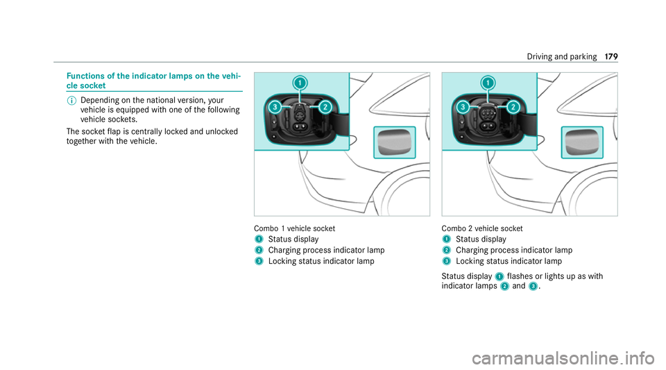
Fu
nctions of the indica tor lamps on the vehi‐
cle soc ket %
Depending on the national version, your
ve hicle is equipped with one of thefo llowing
ve hicle soc kets.
The soc ketflap is centrally loc ked and unloc ked
to ge ther with theve hicle. Combo 1
vehicle soc ket
1 Status display
2 Charging process indicator lamp
3 Locking status indicator lamp Combo 2
vehicle soc ket
1 Status display
2 Charging process indicator lamp
3 Locking status indicator lamp
St atus display 1flashes or lights up as with
indicator lamps 2and 3. Driving and parking
17 9
Page 183 of 629
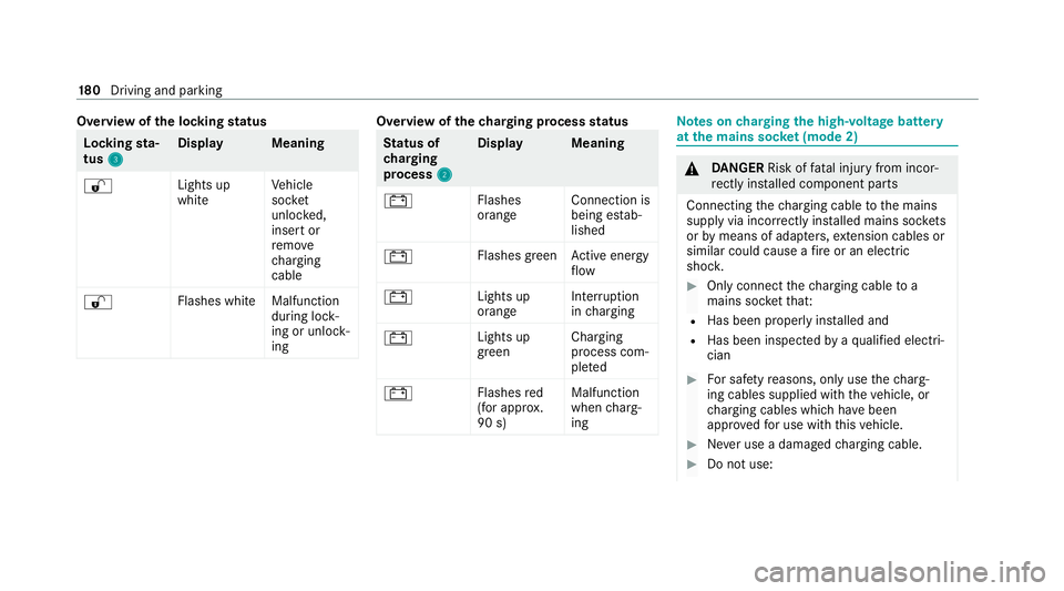
Overview of
the locking status Lock
ingsta‐
tus 3 3 Displa
yM eaning
% Lights up
whiteVe
hicle
soc ket
unlo cked,
insert or
re mo ve
ch arging
cable
% Flashes whit
eMalfunction
during lock‐
ing or unlo ck‐
ing Overview of
thech arging process status St
atus of
ch arging
process 2 2Displa
yM eaning
# Flashes
orangeConnection is
being es
tab‐
lished
# Flashes green
Active energy
fl ow
# Lights up
orangeInter
ruption
in charging
# Lights up
greenCharging
process com‐
ple
ted
# Flashes
red
(for appr ox.
90 s) Malfunction
when
charg‐
ing Note
s oncharging the high-voltage bat tery
at the mains soc ket (mode 2) &
DANG ER Risk of fata l injury from incor‐
re ctly ins talled component parts
Connecting thech arging cable tothe mains
supply via incor rectly ins talled mains soc kets
or by means of adapte rs,ex tension cables or
similar could cause a fire or an electric
shoc k. #
Only connect thech arging cable to a
mains soc ketth at:
R Has been proper lyins talled and
R Has been inspected byaqu alified electri‐
cian #
For saf etyre asons, on lyuse thech arg‐
ing cables supplied with theve hicle, or
ch arging cables which ha vebeen
appr ovedfo r use with this vehicle. #
Never use a dama gedch arging cable. #
Do not use: 18 0
Driving and pa rking
Page 184 of 629
R
Extension cables
R Extension reels
R Multiple soc kets #
Never use soc ket adap ters to connect
th ech arging cable tothe mains soc ket.
The only exception being if the adap ter
has been tested and appr oved bythe
manufacturer forch arging the high-volt‐
age battery of an electric vehicle. #
Obser vethe saf ety no tes in the operat‐
ing instructions forth e soc ket adap ter. Only
thefo llowing charging cables may be used:
R The charging cable supplied with theve hicle.
R Ach arging cable that has been appr oved for
th eve hicle.
The charging process can vary depending on the
po we r supp lyequipment.
Shor terch arging times can be achie ved in the
fo llowing ways:
R Charging at a wallbox.
R Charging at a charging station. When doing so, alw
ays obser vethe local infor‐
mation.
Do not lea vethech arging cable controls hanging
loose from a mains soc ket.
Do not li ftthe controls bythefo llowing compo‐
nent parts:
R The charging cable connec tor.
R The mains plug.
The charging cable should be stowed and held in
place in the bag pr ovided in the boot of theve hi‐
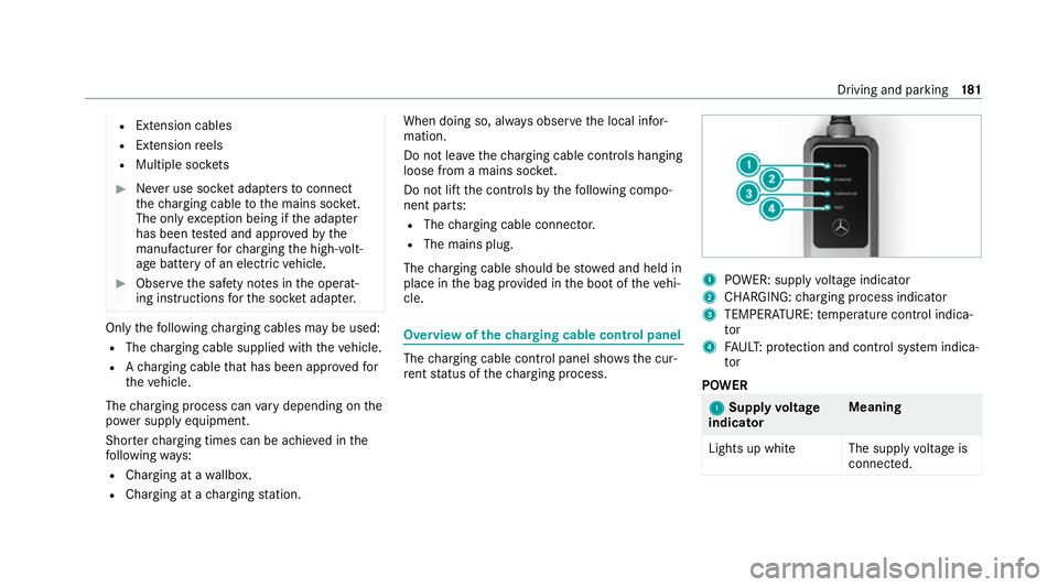
cle. Overview of
thech arging cable control panel The
charging cable control panel sho wsthe cur‐
re nt status of thech arging process. 1
POWER: supply voltage indicator
2 CHARGING: charging process indicator
3 TEMPERATURE: temp erature control indica‐
tor
4 FAUL T:protection and control sy stem indica‐
tor
POWER 1 1
Supply voltage
indicator Meaning
Lights up whit eThe supplyvoltage is
connec ted. Driving and parking
181