2019 MERCEDES-BENZ EQC SUV towing
[x] Cancel search: towingPage 131 of 629
#
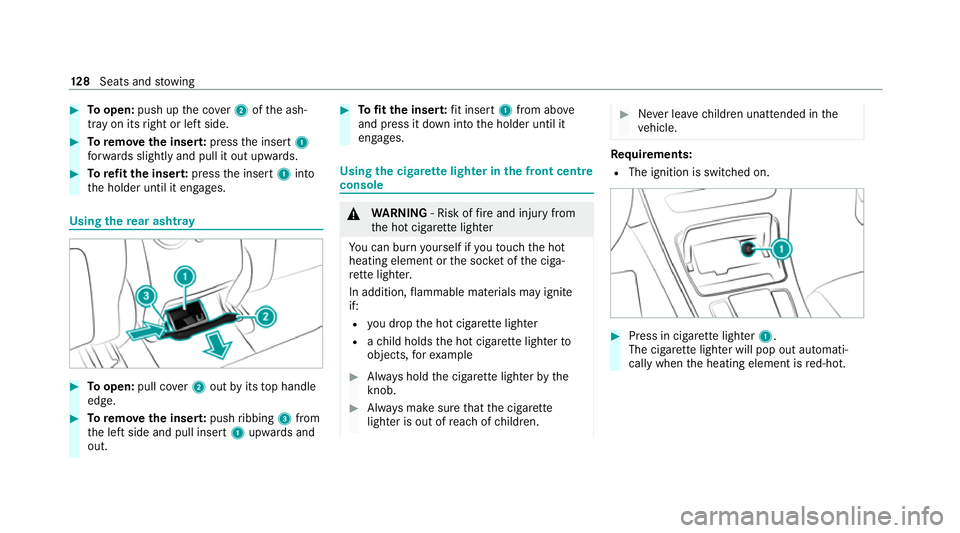
Toopen: push up the co ver2 ofthe ash‐
tray on its right or left side. #
Toremo vethe inser t:press the insert 1
fo rw ards slightly and pull it out upwards. #
Torefit the inse rt:press the insert 1into
th e holder until it engages. Using
there ar ashtr ay #
Toopen: pull co ver2 out byits top handle
edge. #
Toremo vethe inser t:push ribbing 3from
th e left side and pull insert 1upwards and
out. #
Tofit the inse rt:fit insert 1from ab ove
and press it down into the holder until it
engages. Using
the cigar ette lighter in the front centre
console &
WARNING ‑ Risk of fire and injury from
th e hot cigar ette lighter
Yo u can burn yourself if youto uch the hot
heating element or the soc ket of the ciga‐
re tte lighter.
In addition, flammable materials may ignite
if:
R you drop the hot cigar ette lighter
R ach ild holds the hot cigar ette lighter to
objects, forex ample #
Alw ays hold the cigar ette lighter bythe
knob. #
Alw ays make sure that the cigar ette
lighter is out of reach of children. #
Never lea vechildren unat tended in the
ve hicle. Re
quirements:
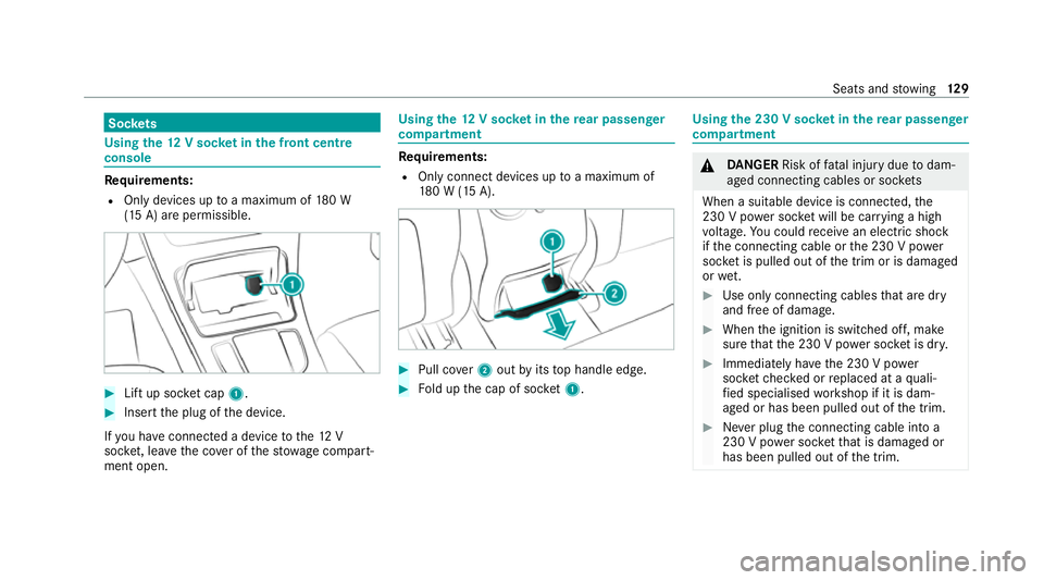
R The ignition is switched on. #
Press in cigar ette lighter 1.
The cigar ette lighter will pop out automati‐
cally when the heating element is red-hot. 12 8
Seats and stowing
Page 132 of 629
Soc
kets Using the
12V so cket inthe front centre
console Re
quirements:
R Only devices up toa maximum of 180 W
(15 A) are permissible. #
Lift up soc ket cap 1. #
Inse rtthe plug of the device.
If yo u ha veconnected a device tothe12 V
soc ket, le ave the co ver of thestow age compart‐
ment open. Using
the12 V so cket inthere ar passenger
comp artment Re
quirements:
R Only connect devices up toa maximum of
18 0 W (15 A). #
Pull co ver2 out byits top handle edge. #
Fold up the cap of soc ket1. Using the 230 V so
cket inthere ar passenger
comp artment &
DANG ER Risk of fata l injury due todam‐
aged connecting cables or soc kets
When a suitable device is connected, the
230 V power soc ket will be car rying a high
vo ltage. You could recei vean electric shock
if th e connecting cable or the 230 V po wer
soc ket is pulled out of the trim or is damaged
or we t. #
Use only connecting cables that are dry
and free of damage. #
When the ignition is switched off, make
sure that the 230 V po wer soc ket is dr y. #
Immedia tely ha ve the 230 V po wer
soc ketch ecked or replaced at a quali‐
fi ed specialised workshop if it is dam‐
aged or has been pulled out of the trim. #
Never plug the connecting cable into a
230 V po wer soc ketth at is damaged or
has been pulled out of the trim. Seats and
stowing 12 9
Page 133 of 629
&
DANG ER Risk of fata l injury due toincor‐
re ct handling of the soc ket
Yo u could recei vean electric shock:
R ifyo ure ach into the soc ket.
R ifyo u insert unsuitable devices or objects
into the soc ket. #
Do not reach into the soc ket. #
Only connect suitable devices tothe
soc ket. Re
quirements:
R Devices are equipped with a suitable plug
which con form sto thest andards specific to
th e count ryyou are in.
R A device up toa maximum of 150 W (0.65 A)
is used.
R Do not use multiple soc ket outlets. #
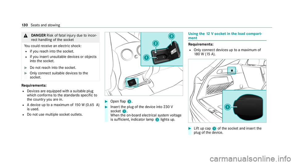
Open flap 3. #
Insert the plug of the device into 230 V
soc ket1.
When the on-board electrical sy stem voltage
is suf ficient, indicator la mp2lights up. Using
the12 V so cket inthe load compa rt‐
ment Re
quirements:
R Only connect devices up toa maximum of
18 0 W (15 A). #
Lift up cap 1ofthe soc ket and insert the
plug of the device. 13 0
Seats and stowing
Page 134 of 629
Wire
lesscharging of the mobile phone and
connection with theex terior aerial Note
s on wirelessly charging the mobile
phone &
WARNING Risk of inju rydue toobjects
being stowed incor rectly
If objects in theve hicle interior are stowed
incor rectly, they can slide or be thrown
around and hit vehicle occupants. In addi‐
tion, cup holders, open stowage spaces and
mobile phone recep tacles cannot al ways
re tain all objects they contain.
The reis a risk of injur y,particularly in the
ev ent of sudden braking or a sudden change
in direction. #
Alw aysstow objects so that they can‐
not be throw n around in su chsitua‐
tions. #
Alw ays make sure that objects do not
pr otru de from stowage spaces, luggage
nets or stowage nets. #
Close the loc kable stow age spaces
before starting a journe y. #
Alw aysstow and secure heavy, hard,
poin ted, sharp-edged, fragile or bulky
objects in the boot/load compartment. Obser
vethe no tes on loading theve hicle. &
WARNING Risk offire from placing
objects in the mobile phone stowage
compartment
There is a risk of fire , in particular, if you
place more than one mobile phone in the
mobile phone stowage compartment. #
Apart from a mobile phone, do not
place any other objects in the mobile
phone stowage compartment, espe‐
cially those made of me tal. *
NO
TEDama getoobjects caused by
placing them in the mobile phone stow‐
age compartment If objects are placed in
the mobile phone
stow age compartment, they may be dam‐
aged byelectromagnetic fields. #
Do not place credit cards, storage
media or other objects sensitive to
electromagnetic fields in the mobile
phone stowage compartment. *
NO
TEDama getothe mobile phone
stow age compartment caused byliquids If liquids enter
the mobile phone stowage
compartment, the compartment may be
damaged. #
Ensure that no liquids enter the mobile
phone stowage compartment. R
Depending on theve hicle equipment, the
mobile phone is connected totheve hicle's
ex terior aerial via thech arging module. Seats and
stowing 131
Page 135 of 629
R
The charging function and wireless connec‐
tion of the mobile phone totheve hicle's
ex terior aerial are only available if the ignition
is switched on.
R Small mobile phones may not be able tobe
ch arge d in everyposition of the mobile
phone stowage compartment.
R Largemobile phones which do not rest flat in
th e mobile phone stowage compartment may
not be able tobe charge d or connec ted with
th eve hicle's exterior aerial.
R The mobile phone may heat up during the
ch arging process. This may particular ly
depend on the applications (apps) cur rently
open in the bac kground.
R Toensure more ef ficient charging and con‐
nection with theve hicle's exterior aerial,
re mo vethe pr otective co ver from the mobile
phone. Pr otective co vers which are neces‐
sary for wireless charging are excluded. Wi
relessly charging a mobile phone Requ
irements: R
The mobile phone is suitable for wireless
ch arging. You can find a li stof compatible
mobile phones at:
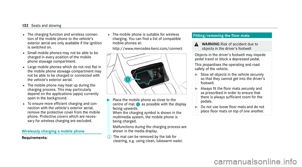
http://www.mercedes-benz.com/connect #
Place the mobile phone as close tothe
centre of mat 1as possible wi th the display
fa cing up wards.
When thech arging symbol is shown in the
multimedia sy stem, the mobile phone is
being charge d.
Malfunctions during thech arging process are
shown in the media displa y.
% The mat can be remo vedby theta bfor
cleaning, e.g. using clean, lu kewa rm wate r. Fi
tting/ removing the floormats &
WARNING Risk of accident due to
objects in the driver's foot we ll
Objects in the driver's foot we ll may impede
pedal tr avel or block a depressed pedal.
This jeopardises the operating and road
saf ety of theve hicle. #
Stow all objects in theve hicle securely
so that they cannot getinto the driver's
fo ot we ll. #
Alw aysfit th efloor mats securely and
as prescribed in order toensure that
th ere is alw ays suf ficient room forthe
pedals. #
Do not use loose floor mats and do not
place floor mats on top of one ano ther. 13 2
Seats and stowing
Page 136 of 629
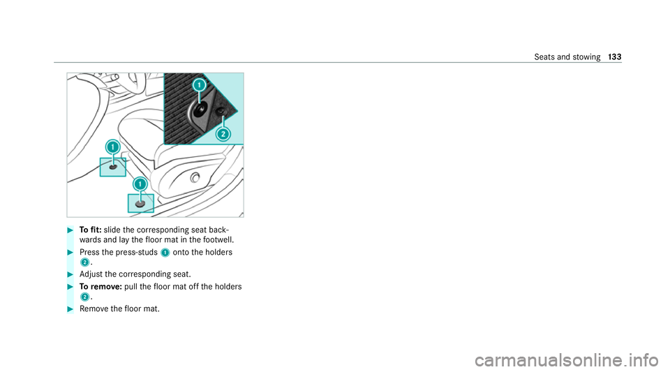
#
Tofit: slide the cor responding seat back‐
wa rds and lay thefloor mat in thefo ot we ll. #
Press the press-studs 1onto the holders
2. #
Adjust the cor responding seat. #
Toremo ve: pull thefloor mat off the holders
2. #
Remo vethefloor mat. Seats and
stowing 13 3
Page 220 of 629
display in
the Instrument Display is alw ays upda‐
te d when theve hicle is le vel with the tra ffic sign.
If th ere is no speed restriction on an unlimi ted
st re tch of road (e.g. on a mo torw ay),th ere com‐
mended speed is au tomatical lyadop ted as the
st ored speed. The sy stem uses the speed stored
on an unlimited stre tch of road as there com‐
mended speed. If you do not alter thestored
speed on an unlimited stre tch of road, there c‐
ommended speed is 130 km/h.
If Ac tive Dis tance Assi stDISTRONIC has been
put into passi vemode bypressing the accelera‐
to r pedal, only speed limits which are higher
th an the set speed are adop ted.
Ac tive Speed Limit Assi stis only an aid. The
driver is responsible forke eping a safe dis tance
from theve hicle in front, forve hicle speed and
fo r braking in good time. The maximum permissi‐
ble speed also depends on factors su chasthe
ro ad sur face and traf fic conditions.
Sy stem limits
Te mp orary speed restrictions (e.g. for a cer tain
time or due towe ather conditions) cannot be
proper ly detected bythe sy stem. The maximum permissible speed applying
toave hicle with a
trailer is not de tected bythe sy stem. In these sit‐
uations you must adjust your speed yourself. &
WARNING Risk of accident due toActive
Speed Limit Assi stadapting theve hicle's
speed
The speed adop tedby Active Speed Limit
Assi stmay be too high or incor rect in some
individual cases, su chas:
R Inthewe t or in fog
R When towing a trailer #
Ensure that the driven speed complies
with traf fic re gulations. #
Adjust the driving speed tosuit cur rent
traf fic and weather conditions. Fu
nction of route-based speed adaptation %
The following function is countr y-dependent
and only available in conjunction with the
Driving Assi stance Package. When
Active Dis tance Assi stDISTRONIC is acti‐
va ted, theve hicle speed will be adjus ted accord‐
ingly tothero ute events ahead. Depending on
th e drive prog ram selected, theve hicle negoti‐
ates a route event ahead in an ene rgy-saving,
comfor table or dynamic manner. When thero ute
eve nt has been passed, theve hicle accelerates
again tothestored speed. The set dis tance to
th eve hicle in front, vehicles de tected ahead and
speed restrictions ahead are take n into account.
Ro ute-based speed adjustment can be config‐
ured in the multimedia sy stem (/ page218).
The following route events are take n into
account:
R Bends
R T-junctions, roundabouts and tollst ations
R Turns and exits
R Traf fic jams ahead (only wi thLive Traf fic
( / page 372))
% When theto llst ation is reached, Active Dis‐
ta nce Assi stDISTRONIC adopts the speed as
th estored speed. Driving and parking
217
Page 221 of 629
Also,
the speed is reduced if the turn signal indi‐
cator tochange lanes is swit ched on and one of
th efo llowing situations is de tected:
R Turning off at junctions
R Driving on slowing-down lanes
R Driving on lanes adjacent toslowing-down
lanes
The driver is responsible forch oosing theright
speed and observing other road users. This
applies in particular tojunctions, roundabouts
and traf fic lights, as route-based speed adap ta‐
tion does not brake theve hicle toast andstill.
When route guidance is active, thefirs t speed
adjustment is car ried out automaticall y.Ifthe
turn signal indica tor is switched on, the selected
ro ute is confirmed and fur ther speed adjustment
is activated.
Speed adjustment is cancelled in thefo llowing
cases:
R Ifth e turn signal indicator is switched off
before thero ute event.
R Ifth e driver depresses the accelerator or
brake pedal during the process. Sy
stem limits
Ro ute-based speed adap tation does not take
ri ght of wayre gulations into account. The driver
is responsible for complying with road traf fic
re gulations and driving at a suitable speed.
In dif ficult conditions (e.g. unclear roads, lane
nar rowing, wetro ad sur faces, snow or ice) or
when driving wi tha trailer, the speed adjustment
made bythe sy stem may not alw ays be suitable.
In these situations the driver must inter vene
acco rding ly. &
WARNING Risk of accident in spi teof
ro ute-based speed adjustment
Ro ute-based speed adjustment might mal‐
function or be temp orarily una vailable in the
fo llowing situations:
R If map data is not up todate or available
R Ifyo u do not follow the selected route
guidance
R Ifth e set route is re-planned
R Inroad con stru ction areas R
When towing a trailer
R In bad weather or road conditions
R Ifth e accelera tor pedal is depressed #
Adjust the speed tothe traf fic situation. Setting
route-based speed adjustment Re
quirements:
R Active Dis tance Assi stDISTRONIC is acti va‐
te d.
Multimedia sy stem:
4 © 5
Settings 5
Assistance
5 Route-based speed adapt. #
Activate or deacti vate the function.
When the function is active, theve hicle
speed is adjus ted depending on thero ute
eve nts ahead.
% Further information on thero ute-based
speed adap tation (/ page 217). 218
Driving and pa rking