Page 252 of 298

R
lug wrench
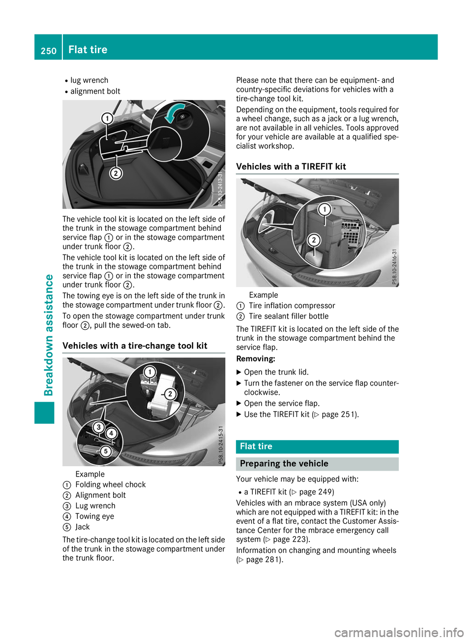
R alignment bolt The vehicle tool kit is located on the left side of
the trunk in the stowage compartment behind
service flap 0043or in the stowage compartment
under trunk floor 0044.
The vehicle tool kit is located on the left side of the trunk in the stowage compartment behind
service flap 0043or in the stowage compartment
under trunk floor 0044.
The towing eye is on the left side of the trunk in
the stowage compartment under trunk floor 0044.
To open the stowage compartment under trunk floor 0044, pull the sewed-on tab.
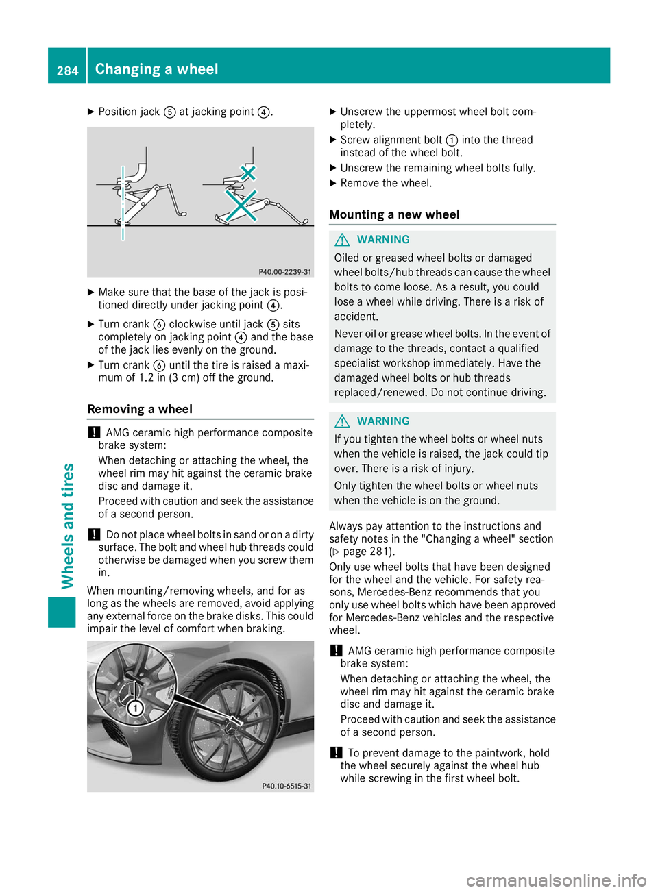
Vehicles with a tire-change tool kit Example
0043 Folding wheel chock
0044 Alignment bolt
0087 Lug wrench
0085 Towing eye
0083 Jack
The tire-change tool kit is located on the left side of the trunk in the stowage compartment under the trunk floor. Please note that there can be equipment- and
country-specific deviations for vehicles with a
tire-change tool kit.
Depending on the equipment, tools required for
a wheel change, such as a jack or a lug wrench, are not available in all vehicles. Tools approved
for your vehicle are available at a qualified spe-
cialist workshop.
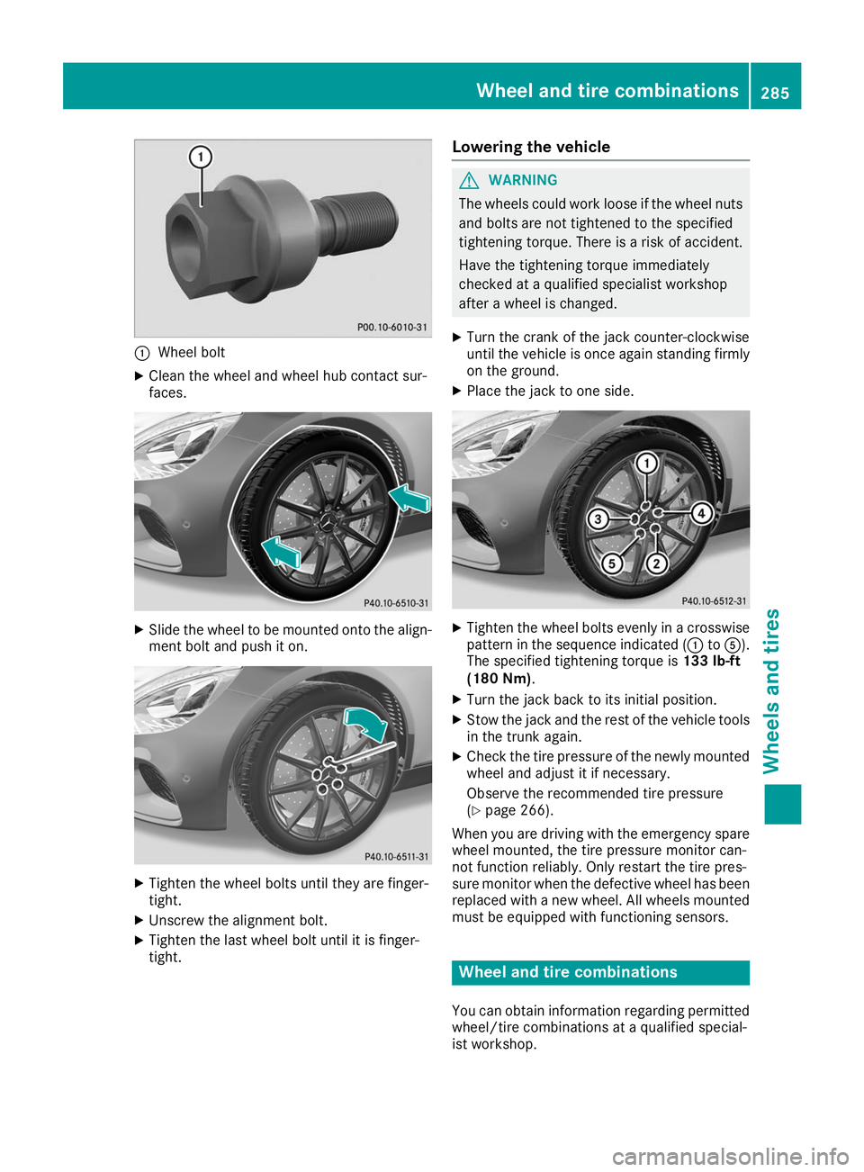
Vehicles with a TIREFIT kit Example
0043 Tire inflation compressor
0044 Tire sealant filler bottle
The TIREFIT kit is located on the left side of the
trunk in the stowage compartment behind the
service flap.
Removing:
X Open the trunk lid.
X Turn the fastener on the service flap counter-
clockwise.
X Open the service flap.
X Use the TIREFIT kit (Y page 251). Flat tire
Preparing the vehicle
Your vehicle may be equipped with: R a TIREFIT kit (Y page 249)
Vehicles with an mbrace system (USA only)
which are not equipped with a TIREFIT kit: in the event of a flat tire, contact the Customer Assis-
tance Center for the mbrace emergency call
system (Y page 223).
Information on changing and mounting wheels
(Y page 281). 250
Flat tireBreakdown assistance
Page 286 of 298

X
Position jack 0083at jacking point 0085. X
Make sure that the base of the jack is posi-
tioned directly under jacking point 0085.
X Turn crank 0084clockwise until jack 0083sits
completely on jacking point 0085and the base
of the jack lies evenly on the ground.
X Turn crank 0084until the tire is raised a maxi-
mum of 1.2 in (3 cm) off the ground.
Removing a wheel !
AMG ceramic high performance composite
brake system:
When detaching or attaching the wheel, the
wheel rim may hit against the ceramic brake
disc and damage it.
Proceed with caution and seek the assistance of a second person.
! Do not place wheel bolts in sand or on a dirty
surface. The bolt and wheel hub threads could
otherwise be damaged when you screw them in.
When mounting/removing wheels, and for as
long as the wheels are removed, avoid applying any external force on the brake disks. This could
impair the level of comfort when braking. X
Unscrew the uppermost wheel bolt com-
pletely.
X Screw alignment bolt 0043into the thread
instead of the wheel bolt.
X Unscrew the remaining wheel bolts fully.
X Remove the wheel.
Mounting a new wheel G
WARNING
Oiled or greased wheel bolts or damaged
wheel bolts/hub threads can cause the wheel bolts to come loose. As a result, you could
lose a wheel while driving. There is a risk of
accident.
Never oil or grease wheel bolts. In the event ofdamage to the threads, contact a qualified
specialist workshop immediately. Have the
damaged wheel bolts or hub threads
replaced/renewed. Do not continue driving. G
WARNING
If you tighten the wheel bolts or wheel nuts
when the vehicle is raised, the jack could tip
over. There is a risk of injury.
Only tighten the wheel bolts or wheel nuts
when the vehicle is on the ground.
Always pay attention to the instructions and
safety notes in the "Changing a wheel" section
(Y page 281).
Only use wheel bolts that have been designed
for the wheel and the vehicle. For safety rea-
sons, Mercedes-Benz recommends that you
only use wheel bolts which have been approved for Mercedes-Benz vehicles and the respective
wheel.
! AMG ceramic high performance composite
brake system:
When detaching or attaching the wheel, the
wheel rim may hit against the ceramic brake
disc and damage it.
Proceed with caution and seek the assistance
of a second person.
! To prevent damage to the paintwork, hold
the wheel securely against the wheel hub
while screwing in the first wheel bolt. 284
Changing a wheelWheels and tires
Page 287 of 298

0043
Wheel bolt
X Clean the wheel and wheel hub contact sur-
faces. X
Slide the wheel to be mounted onto the align-
ment bolt and push it on. X
Tighten the wheel bolts until they are finger-
tight.
X Unscrew the alignment bolt.
X Tighten the last wheel bolt until it is finger-
tight. Lowering the vehicle G
WARNING
The wheels could work loose if the wheel nuts and bolts are not tightened to the specified
tightening torque. There is a risk of accident.
Have the tightening torque immediately
checked at a qualified specialist workshop
after a wheel is changed.
X Turn the crank of the jack counter-clockwise
until the vehicle is once again standing firmly
on the ground.
X Place the jack to one side. X
Tighten the wheel bolts evenly in a crosswise
pattern in the sequence indicated (0043 to0083).
The specified tightening torque is 133 lb-ft
(180 Nm).
X Turn the jack back to its initial position.
X Stow the jack and the rest of the vehicle tools
in the trunk again.
X Check the tire pressure of the newly mounted
wheel and adjust it if necessary.
Observe the recommended tire pressure
(Y page 266).
When you are driving with the emergency spare
wheel mounted, the tire pressure monitor can-
not function reliably. Only restart the tire pres-
sure monitor when the defective wheel has been replaced with a new wheel. All wheels mounted
must be equipped with functioning sensors. Wheel and tire combinations
You can obtain information regarding permitted wheel/tire combinations at a qualified special-
ist workshop. Wheel and tire combinations
285Wheels and tires Z