2019 MERCEDES-BENZ AMG GT ROADSTER clock
[x] Cancel search: clockPage 75 of 298
If a locked door is opened from the inside, the
previous unlock status of the vehicle will be
taken into consideration if:
R the vehicle was locked using the locking but-
ton for the central locking, or
R locked automatically
The vehicle will be fully unlocked if it had previ-
ously been fully unlocked. If only the driver's
door had been previously unlocked, only the
door which has been opened from the inside is
unlocked. Automatic locking feature
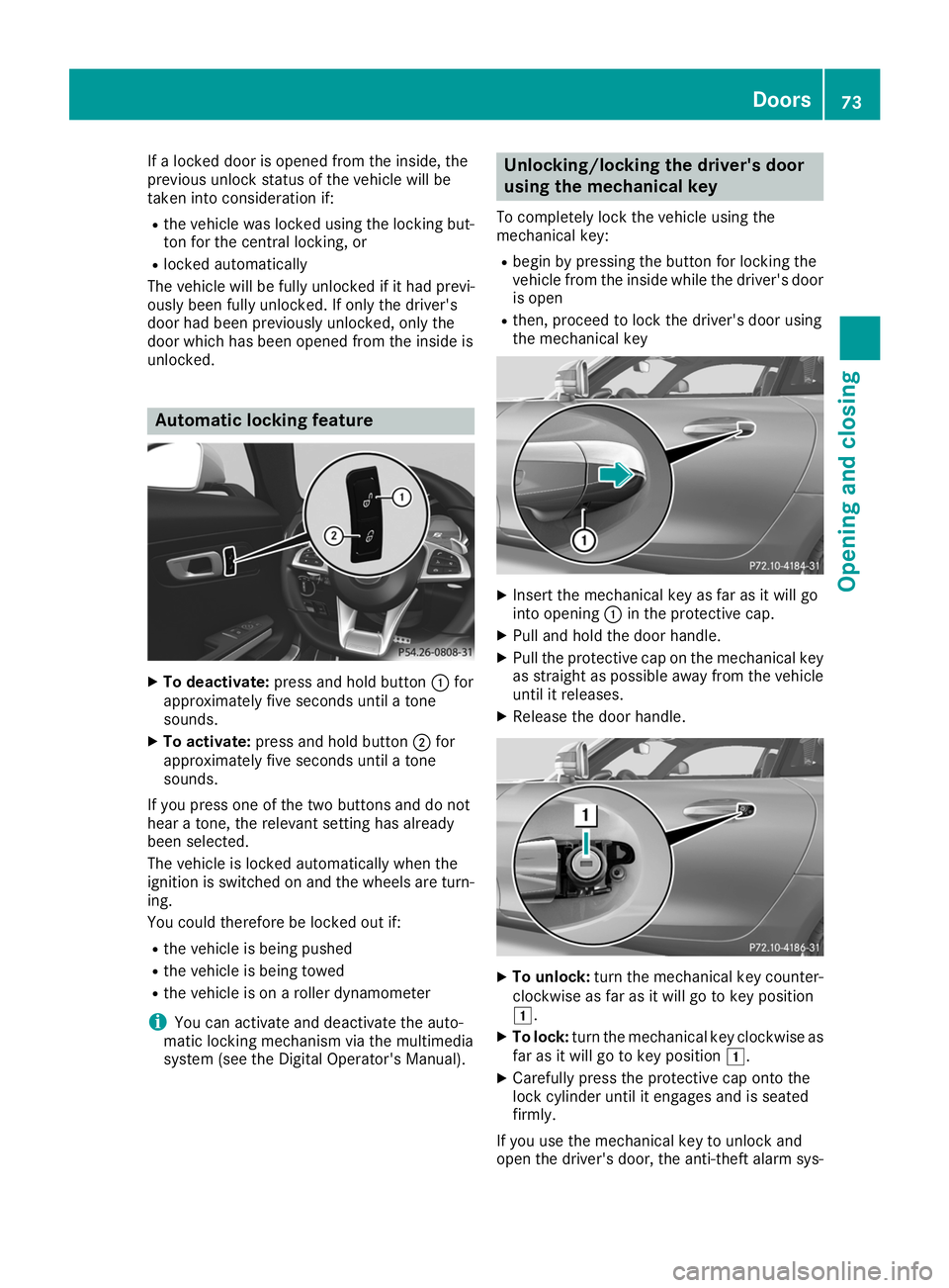
X
To deactivate: press and hold button 0043for
approximately five seconds until a tone
sounds.
X To activate: press and hold button 0044for
approximately five seconds until a tone
sounds.
If you press one of the two buttons and do not
hear a tone, the relevant setting has already
been selected.
The vehicle is locked automatically when the
ignition is switched on and the wheels are turn-
ing.
You could therefore be locked out if:
R the vehicle is being pushed
R the vehicle is being towed
R the vehicle is on a roller dynamometer
i You can activate and deactivate the auto-
matic locking mechanism via the multimedia
system (see the Digital Operator's Manual). Unlocking/locking the driver's door
using the mechanical key
To completely lock the vehicle using the
mechanical key: R begin by pressing the button for locking the
vehicle from the inside while the driver's door
is open
R then, proceed to lock the driver's door using
the mechanical key X
Insert the mechanical key as far as it will go
into opening 0043in the protective cap.
X Pull and hold the door handle.
X Pull the protective cap on the mechanical key
as straight as possible away from the vehicleuntil it releases.
X Release the door handle. X
To unlock: turn the mechanical key counter-
clockwise as far as it will go to key position
0047.
X To lock: turn the mechanical key clockwise as
far as it will go to key position 0047.
X Carefully press the protective cap onto the
lock cylinder until it engages and is seated
firmly.
If you use the mechanical key to unlock and
open the driver's door, the anti-theft alarm sys- Doors
73Opening and closing Z
Page 128 of 298
If you overfill the fuel tank, fuel could spray out
when the fuel pump nozzle is removed.
For further information on fuel and fuel quality
(Y page 289). Refueling
General information Pay attention to the important safety notes
(Y page 125).
If you unlock/lock the vehicle from the outside,
the fuel filler flap also unlocks/locks.
The position of the fuel filler cap is displayed
00B6 in the instrument cluster. The arrow next
to the filling pump indicates the side of the vehi-
cle.
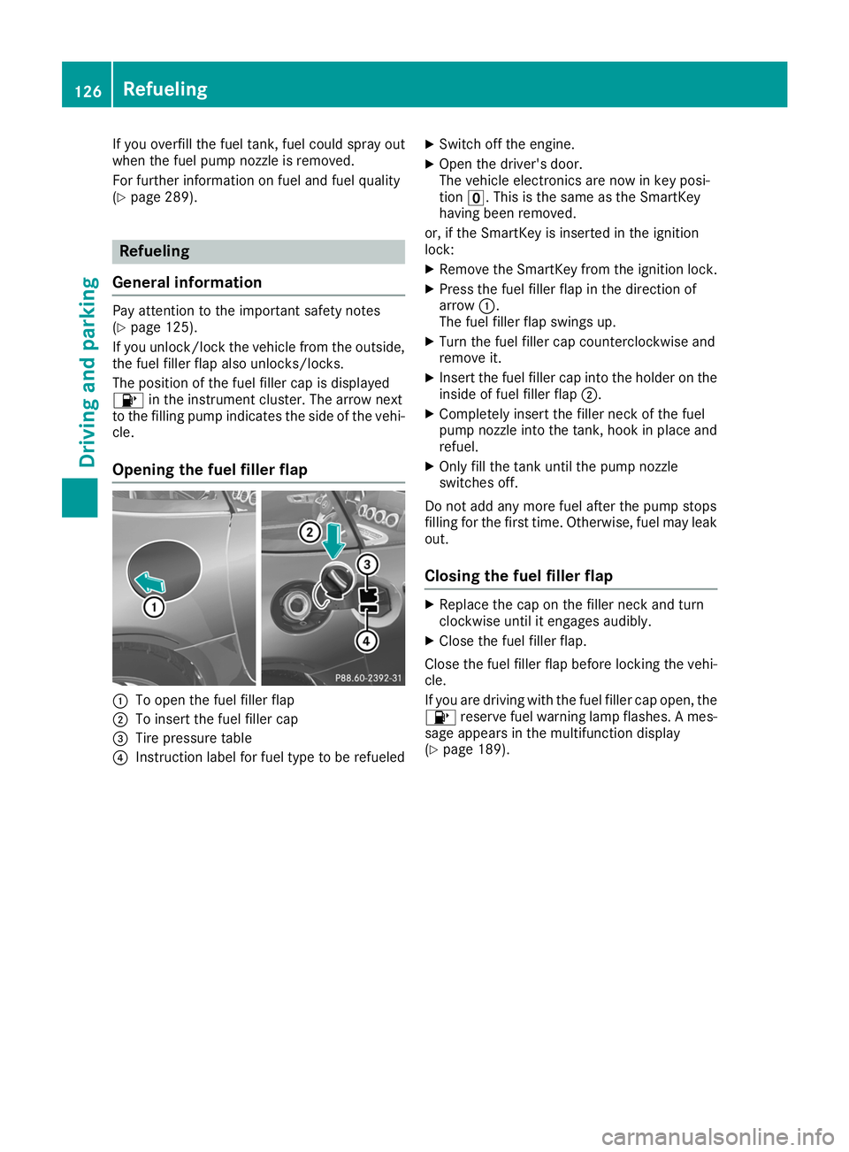
Opening the fuel filler flap 0043
To open the fuel filler flap
0044 To insert the fuel filler cap
0087 Tire pressure table
0085 Instruction label for fuel type to be refueled X
Switch off the engine.
X Open the driver's door.
The vehicle electronics are now in key posi-
tion 0092. This is the same as the SmartKey
having been removed.
or, if the SmartKey is inserted in the ignition
lock: X Remove the SmartKey from the ignition lock.
X Press the fuel filler flap in the direction of
arrow 0043.
The fuel filler flap swings up.
X Turn the fuel filler cap counterclockwise and
remove it.
X Insert the fuel filler cap into the holder on the
inside of fuel filler flap 0044.
X Completely insert the filler neck of the fuel
pump nozzle into the tank, hook in place and
refuel.
X Only fill the tank until the pump nozzle
switches off.
Do not add any more fuel after the pump stops
filling for the first time. Otherwise, fuel may leak out.
Closing the fuel filler flap X
Replace the cap on the filler neck and turn
clockwise until it engages audibly.
X Close the fuel filler flap.
Close the fuel filler flap before locking the vehi-
cle.
If you are driving with the fuel filler cap open, the 00B6 reserve fuel warning lamp flashes. A mes-
sage appears in the multifunction display
(Y page 189). 126
RefuelingDriving and parking
Page 240 of 298
Display messages
Possible causes/consequences and
0050
0050Solutions Engine Oil Level
Engine Oil Level
Correct Correct
Measurement
Measurement
Only if Vehicle Is
Only if Vehicle Is
on Level Ground on Level Ground The vehicle is not parked on a level surface.
X Park the vehicle on a level surface. Engine Oil Level
Engine Oil Level
Not Measurable Not Measurable Oil level measurement with the oil dipstick is possible. The measuring
system is malfunctioning.
X Visit a qualified specialist workshop. Adding engine oil
G
WARNING
Certain components in the engine compart-
ment, such as the engine, radiator and parts
of the exhaust system, can become very hot.
Working in the engine compartment poses a
risk of injury.
Where possible, let the engine cool down and touch only the components described in the
following. G
WARNING
If engine oil comes into contact with hot com- ponents in the engine compartment, it may
ignite. There is a risk of fire and injury.
Make sure that engine oil is not spilled next to
the filler neck. Let the engine cool down and
thoroughly clean the engine oil off the com-
ponents before starting the engine. H
Environmental note
When adding oil, take care not to spill any. If
oil enters the soil or waterways, it is harmful to the environment.
! Use only engine oils and oil filters that are
approved for vehicles with a service system. A list of the engine oils and oil filters that have
been tested and approved in accordance with
Mercedes-Benz Specifications for Service
Products is available at any authorized
Mercedes-Benz Center. The following cause engine failure or damage
to the exhaust system:
R Use of engine oils and oil filters that have
not been expressly approved for the service
system
R Replacement of engine oil and oil filter after
the replacement interval specified by the
service system has expired
R Use of engine oil additives
! Do not add too much oil. If the oil level is
above the "max" mark on the dipstick, too
much oil has been added. This can lead to
damage to the engine or the catalytic con-
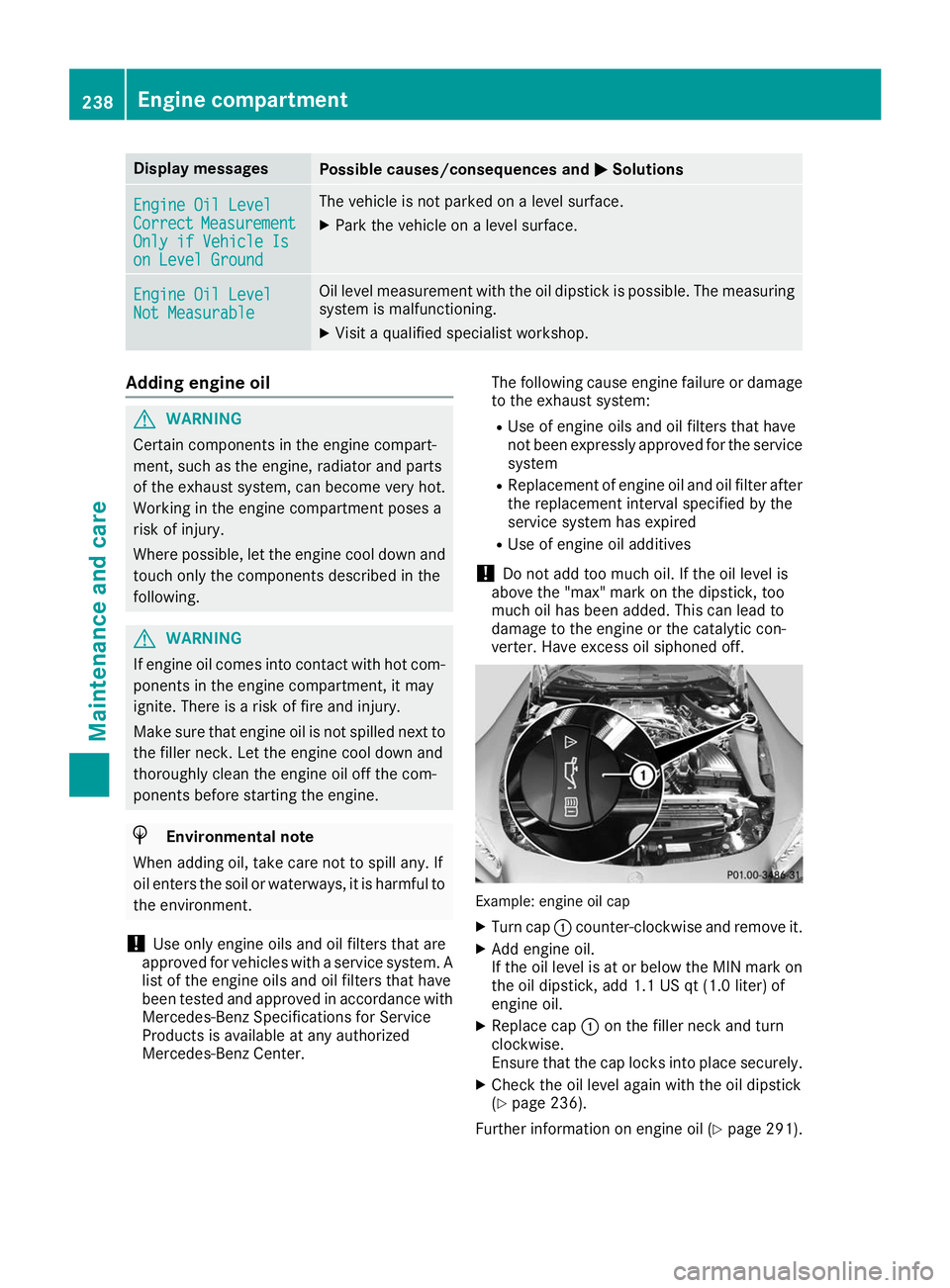
verter. Have excess oil siphoned off. Example: engine oil cap
X Turn cap 0043counter-clockwise and remove it.
X Add engine oil.
If the oil level is at or below the MIN mark on
the oil dipstick, add 1.1 US qt (1.0 liter) of
engine oil.
X Replace cap 0043on the filler neck and turn
clockwise.
Ensure that the cap locks into place securely.
X Check the oil level again with the oil dipstick
(Y page 236).
Further information on engine oil (Y page 291).238
Engine compartmentMaintenance and care
Page 241 of 298
Additional service products
Checking coolant level G
WARNING
Certain components in the engine compart-
ment, such as the engine, radiator and parts
of the exhaust system, can become very hot.
Working in the engine compartment poses a
risk of injury.
Where possible, let the engine cool down and touch only the components described in the
following. G
WARNING
Opening the hood when the engine is over-
heated or when there is a fire in the engine
compartment could expose you to hot gases
or other service products. There is a risk of
injury.
Let an overheated engine cool down before
opening the hood. If there is a fire in the
engine compartment, keep the hood closed
and contact the fire department. G
WARNING
The cooling system is pressurized, particularly when the motor is warm. If you open the cap, you could be scalded if hot coolant sprays out.
There is a risk of injury.
Let the engine cool down before you open the
cap. Wear protective gloves and protective
eyewear when opening. Open the cap slowly
to release pressure.
! Before starting your journey, make sure that
all engine covers are installed. Otherwise, the engine can be damaged, e.g. through over-
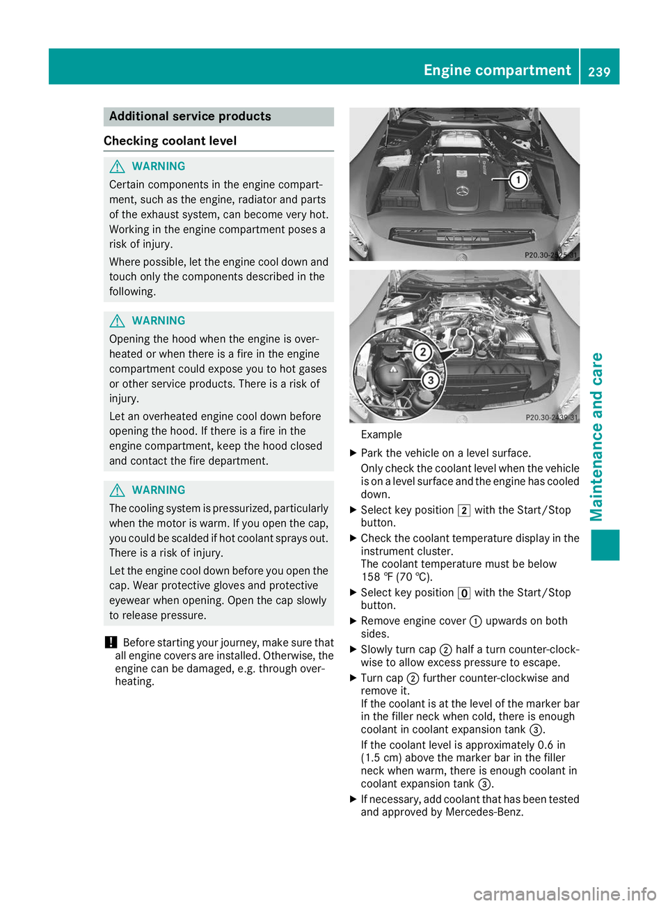
heating. Example
X Park the vehicle on a level surface.
Only check the coolant level when the vehicle
is on a level surface and the engine has cooled
down.
X Select key position 0048with the Start/Stop
button.
X Check the coolant temperature display in the
instrument cluster.
The coolant temperature must be below
158 ‡ (70 †).
X Select key position 0092with the Start/Stop
button.
X Remove engine cover 0043upwards on both
sides.
X Slowly turn cap 0044half a turn counter-clock-
wise to allow excess pressure to escape.
X Turn cap 0044further counter-clockwise and
remove it.
If the coolant is at the level of the marker bar in the filler neck when cold, there is enough
coolant in coolant expansion tank 0087.
If the coolant level is approximately 0.6 in
(1.5 cm) above the marker bar in the filler
neck when warm, there is enough coolant in
coolant expansion tank 0087.
X If necessary, add coolant that has been tested
and approved by Mercedes-Benz. Engine compartment
239Maintenance and care Z
Page 242 of 298
X
Replace cap 0044and turn it clockwise as far as
it will go.
X Replace engine cover 0043.
For further information on coolant, see
(Y page 292).
Windshield washer system G
WARNING
Certain components in the engine compart-
ment, such as the engine, radiator and parts
of the exhaust system, can become very hot.
Working in the engine compartment poses a
risk of injury.
Where possible, let the engine cool down and touch only the components described in the
following. G
WARNING
Windshield washer concentrate is highly flam- mable. If windshield washer concentrate getsonto hot components of the engine or the
exhaust system, it can ignite. There is a risk of
fire and injury.
Make sure that windshield washer concen-
trate is not spilled in the vicinity of the filler
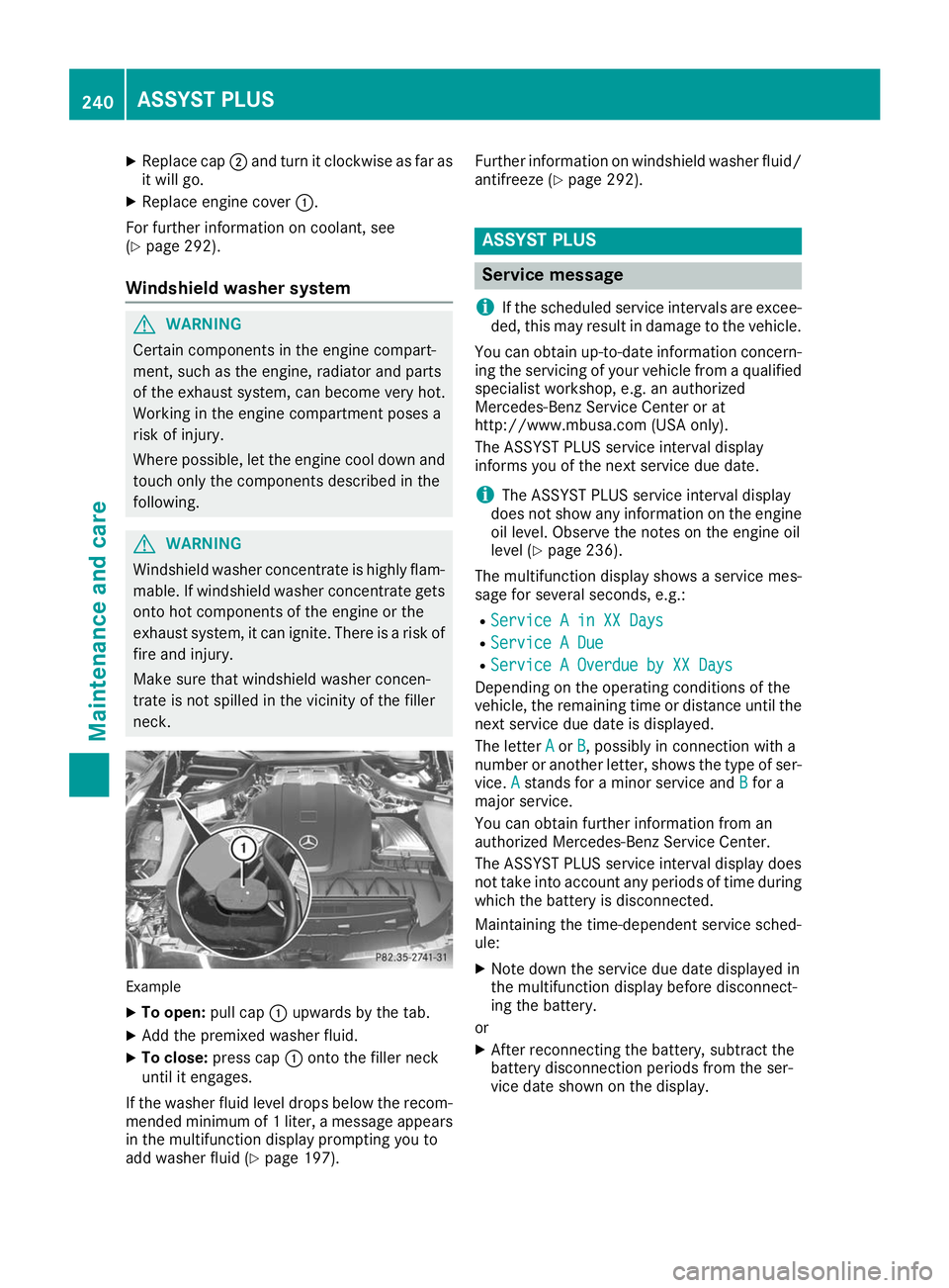
neck. Example
X To open: pull cap0043upwards by the tab.
X Add the premixed washer fluid.
X To close: press cap 0043onto the filler neck
until it engages.
If the washer fluid level drops below the recom- mended minimum of 1 liter, a message appears
in the multifunction display prompting you to
add washer fluid (Y page 197). Further information on windshield washer fluid/
antifreeze (Y page 292). ASSYST PLUS
Service message
i If the scheduled service intervals are excee-
ded, this may result in damage to the vehicle.
You can obtain up-to-date information concern-
ing the servicing of your vehicle from a qualified specialist workshop, e.g. an authorized
Mercedes-Benz Service Center or at
http://www.mbusa.com (USA only).
The ASSYST PLUS service interval display
informs you of the next service due date.
i The ASSYST PLUS service interval display
does not show any information on the engine oil level. Observe the notes on the engine oil
level (Y page 236).
The multifunction display shows a service mes-
sage for several seconds, e.g.: R Service A in XX Days Service A in XX Days
R Service A Due
Service A Due
R Service A Overdue by XX Days
Service A Overdue by XX Days
Depending on the operating conditions of the
vehicle, the remaining time or distance until the
next service due date is displayed.
The letter A Aor B
B, possibly in connection with a
number or another letter, shows the type of ser-
vice. A
Astands for a minor service and B
Bfor a
major service.
You can obtain further information from an
authorized Mercedes-Benz Service Center.
The ASSYST PLUS service interval display does
not take into account any periods of time during
which the battery is disconnected.
Maintaining the time-dependent service sched-
ule:
X Note down the service due date displayed in
the multifunction display before disconnect-
ing the battery.
or
X After reconnecting the battery, subtract the
battery disconnection periods from the ser-
vice date shown on the display. 240
ASSYST PLUSMaintenance and care
Page 252 of 298
R
lug wrench
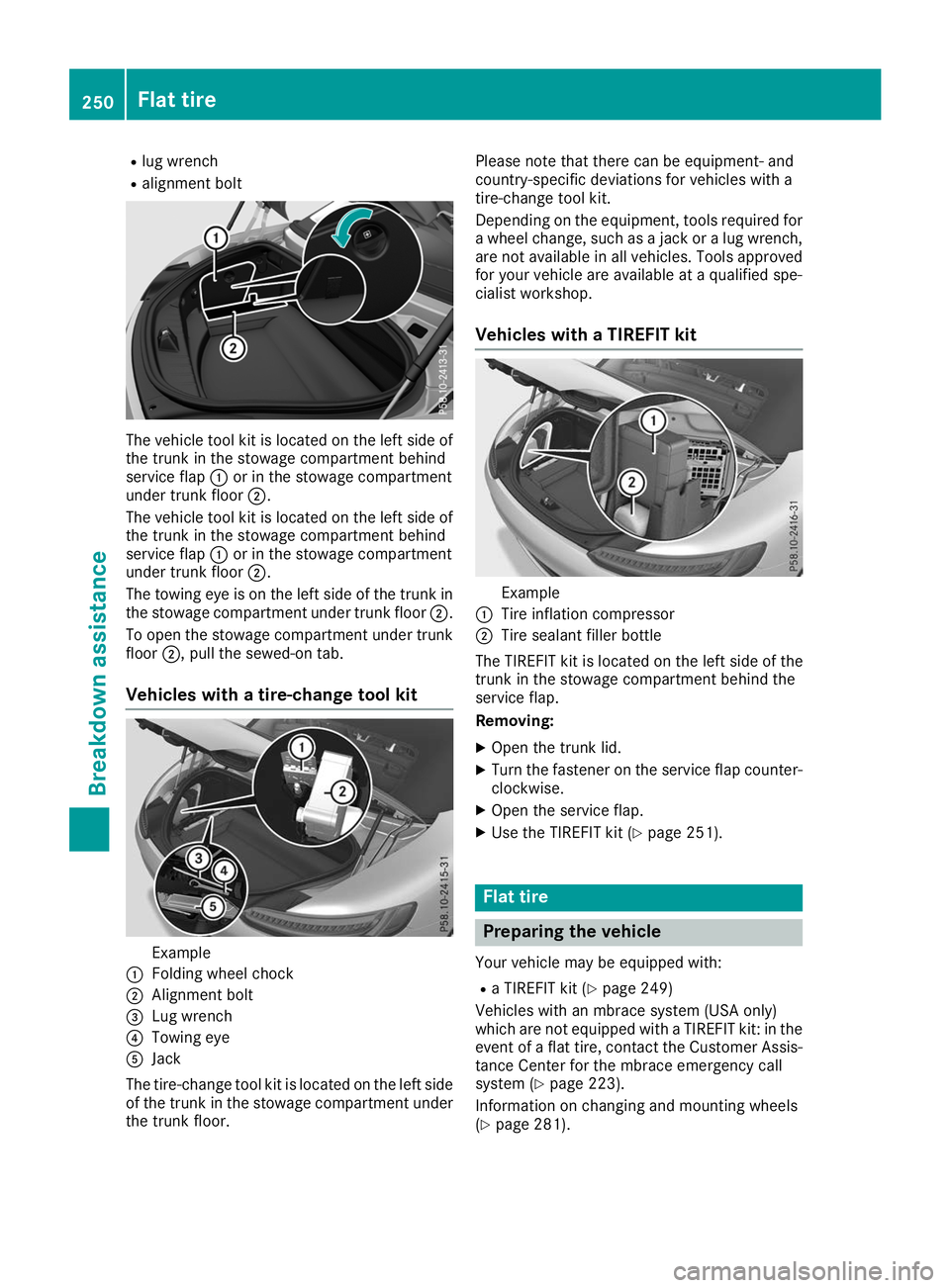
R alignment bolt The vehicle tool kit is located on the left side of
the trunk in the stowage compartment behind
service flap 0043or in the stowage compartment
under trunk floor 0044.
The vehicle tool kit is located on the left side of the trunk in the stowage compartment behind
service flap 0043or in the stowage compartment
under trunk floor 0044.
The towing eye is on the left side of the trunk in
the stowage compartment under trunk floor 0044.
To open the stowage compartment under trunk floor 0044, pull the sewed-on tab.
Vehicles with a tire-change tool kit Example
0043 Folding wheel chock
0044 Alignment bolt
0087 Lug wrench
0085 Towing eye
0083 Jack
The tire-change tool kit is located on the left side of the trunk in the stowage compartment under the trunk floor. Please note that there can be equipment- and
country-specific deviations for vehicles with a
tire-change tool kit.
Depending on the equipment, tools required for
a wheel change, such as a jack or a lug wrench, are not available in all vehicles. Tools approved
for your vehicle are available at a qualified spe-
cialist workshop.
Vehicles with a TIREFIT kit Example
0043 Tire inflation compressor
0044 Tire sealant filler bottle
The TIREFIT kit is located on the left side of the
trunk in the stowage compartment behind the
service flap.
Removing:
X Open the trunk lid.
X Turn the fastener on the service flap counter-
clockwise.
X Open the service flap.
X Use the TIREFIT kit (Y page 251). Flat tire
Preparing the vehicle
Your vehicle may be equipped with: R a TIREFIT kit (Y page 249)
Vehicles with an mbrace system (USA only)
which are not equipped with a TIREFIT kit: in the event of a flat tire, contact the Customer Assis-
tance Center for the mbrace emergency call
system (Y page 223).
Information on changing and mounting wheels
(Y page 281). 250
Flat tireBreakdown assistance
Page 262 of 298
X
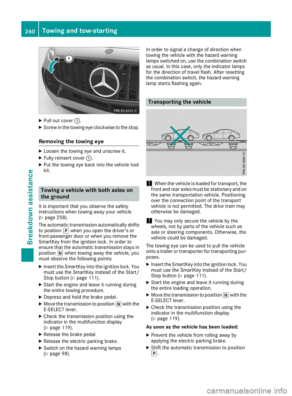
Pull out cover 0043.
X Screw in the towing eye clockwise to the stop.
Removing the towing eye X
Loosen the towing eye and unscrew it.
X Fully reinsert cover 0043.
X Put the towing eye back into the vehicle tool
kit. Towing a vehicle with both axles on
the ground
It is important that you observe the safety
instructions when towing away your vehicle
(Y page 258).
The automatic transmission automatically shifts
to position 005Dwhen you open the driver's or
front-passenger door or when you remove the
SmartKey from the ignition lock. In order to
ensure that the automatic transmission stays in position 005Cwhen towing away the vehicle, you
must observe the following points:
X Insert the SmartKey into the ignition lock. You
must use the SmartKey instead of the Start/
Stop button (Y page 111).
X Start the engine and leave it running during
the entire towing procedure.
X Depress and hold the brake pedal.
X Move the transmission to position 005Cwith the
E-SELECT lever.
X Check the transmission position using the
indicator in the multifunction display
(Y page 119).
X Release the brake pedal.
X Release the electric parking brake.
X Switch on the hazard warning lamps
(Y page 98). In order to signal a change of direction when
towing the vehicle with the hazard warning
lamps switched on, use the combination switch as usual. In this case, only the indicator lamps
for the direction of travel flash. After resetting
the combination switch, the hazard warning
lamp starts flashing again. Transporting the vehicle
!
When the vehicle is loaded for transport, the
front and rear axles must be stationary and on the same transportation vehicle. Positioning
over the connection point of the transport
vehicle is not permitted. The drive train may
otherwise be damaged.
! You may only secure the vehicle by the
wheels, not by parts of the vehicle such as
axle or steering components. Otherwise, the
vehicle could be damaged.
The towing eye can be used to pull the vehicle
onto a trailer or transporter for transporting pur- poses.
X Insert the SmartKey into the ignition lock. You
must use the SmartKey instead of the Start/
Stop button (Y page 111).
X Start the engine and leave it running during
the entire loading operation.
X Move the transmission to position 005Cwith the
E-SELECT lever.
X Check the transmission position using the
indicator in the multifunction display
(Y page 119).
As soon as the vehicle has been loaded:
X Prevent the vehicle from rolling away by
applying the electric parking brake.
X Shift the automatic transmission to position
005D. 260
Towing and tow-startingBreakdown assistance
Page 285 of 298
R
Before raising the vehicle, secure it from roll-
ing away by applying the parking brake and
inserting wheel chocks. Do not disengage the parking brake while the vehicle is raised.
R The jack must be placed on a firm, flat and
non-slip surface. On a loose surface, a large,
flat, load-bearing underlay must be used. On a slippery surface, a non-slip underlay must be
used, e.g. rubber mats.
R Do not use wooden blocks or similar objects
as a jack underlay. Otherwise, the jack will not
be able to achieve its load-bearing capacity
due to the restricted height.
R Make sure that the distance between the
underside of the tires and the ground does not
exceed 1.2 in (3 cm).
R Do not place your hands or feet under the
raised vehicle.
R Do not lie under the vehicle.
R Do not start the engine when the vehicle is
raised.
R Do not open or close a door or the trunk lid
when the vehicle is raised.
R Make sure that no persons are present in the
vehicle when the vehicle is raised.
Vehicles with hub caps: the hub cap covers
the wheel bolts. Before you can unscrew the
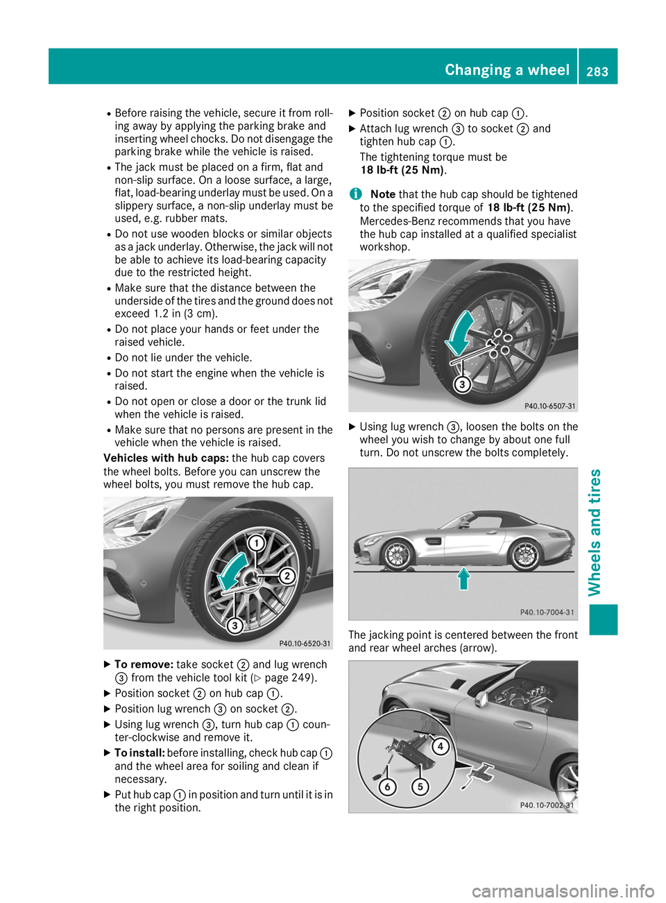
wheel bolts, you must remove the hub cap. X
To remove: take socket0044and lug wrench
0087 from the vehicle tool kit (Y page 249).
X Position socket 0044on hub cap 0043.
X Position lug wrench 0087on socket 0044.
X Using lug wrench 0087, turn hub cap0043coun-
ter-clockwise and remove it.
X To install: before installing, check hub cap 0043
and the wheel area for soiling and clean if
necessary.
X Put hub cap 0043in position and turn until it is in
the right position. X
Position socket 0044on hub cap 0043.
X Attach lug wrench 0087to socket 0044and
tighten hub cap 0043.
The tightening torque must be
18 lb-ft (25 Nm).
i Note
that the hub cap should be tightened
to the specified torque of 18 lb-ft (25 Nm).
Mercedes-Benz recommends that you have
the hub cap installed at a qualified specialist
workshop. X
Using lug wrench 0087, loosen the bolts on the
wheel you wish to change by about one full
turn. Do not unscrew the bolts completely. The jacking point is centered between the front
and rear wheel arches (arrow). Changing a wheel
283Wheels and tires Z