2019 MERCEDES-BENZ AMG GT ROADSTER oil
[x] Cancel search: oilPage 251 of 298
Where will I find...?
Reflective safety jacket
Removing/replacing the reflective
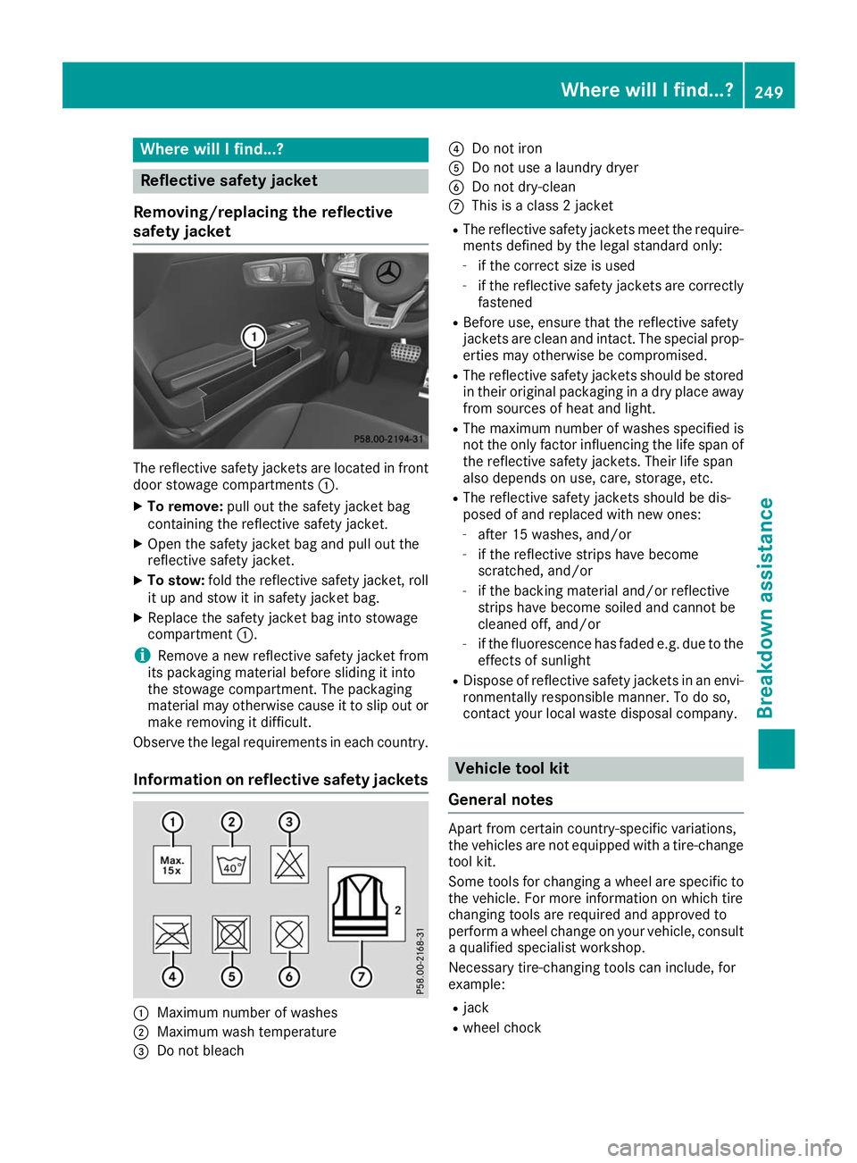
safety jacket The reflective safety jackets are located in front
door stowage compartments 0043.
X To remove: pull out the safety jacket bag
containing the reflective safety jacket.
X Open the safety jacket bag and pull out the
reflective safety jacket.
X To stow: fold the reflective safety jacket, roll
it up and stow it in safety jacket bag.
X Replace the safety jacket bag into stowage
compartment 0043.
i Remove a new reflective safety jacket from
its packaging material before sliding it into
the stowage compartment. The packaging
material may otherwise cause it to slip out or
make removing it difficult.
Observe the legal requirements in each country.
Information on reflective safety jackets 0043
Maximum number of washes
0044 Maximum wash temperature
0087 Do not bleach 0085
Do not iron
0083 Do not use a laundry dryer
0084 Do not dry-clean
006B This is a class 2 jacket
R The reflective safety jackets meet the require-
ments defined by the legal standard only:
- if the correct size is used
- if the reflective safety jackets are correctly
fastened
R Before use, ensure that the reflective safety
jackets are clean and intact. The special prop-
erties may otherwise be compromised.
R The reflective safety jackets should be stored
in their original packaging in a dry place away
from sources of heat and light.
R The maximum number of washes specified is
not the only factor influencing the life span of
the reflective safety jackets. Their life span
also depends on use, care, storage, etc.
R The reflective safety jackets should be dis-
posed of and replaced with new ones:
- after 15 washes, and/or
- if the reflective strips have become
scratched, and/or
- if the backing material and/or reflective
strips have become soiled and cannot be
cleaned off, and/or
- if the fluorescence has faded e.g. due to the
effects of sunlight
R Dispose of reflective safety jackets in an envi-
ronmentally responsible manner. To do so,
contact your local waste disposal company. Vehicle tool kit
General notes Apart from certain country-specific variations,
the vehicles are not equipped with a tire-change
tool kit.
Some tools for changing a wheel are specific to the vehicle. For more information on which tire
changing tools are required and approved to
perform a wheel change on your vehicle, consult
a qualified specialist workshop.
Necessary tire-changing tools can include, for
example:
R jack
R wheel chock Where will I find...?
249Breakdown assistance
Page 254 of 298
X
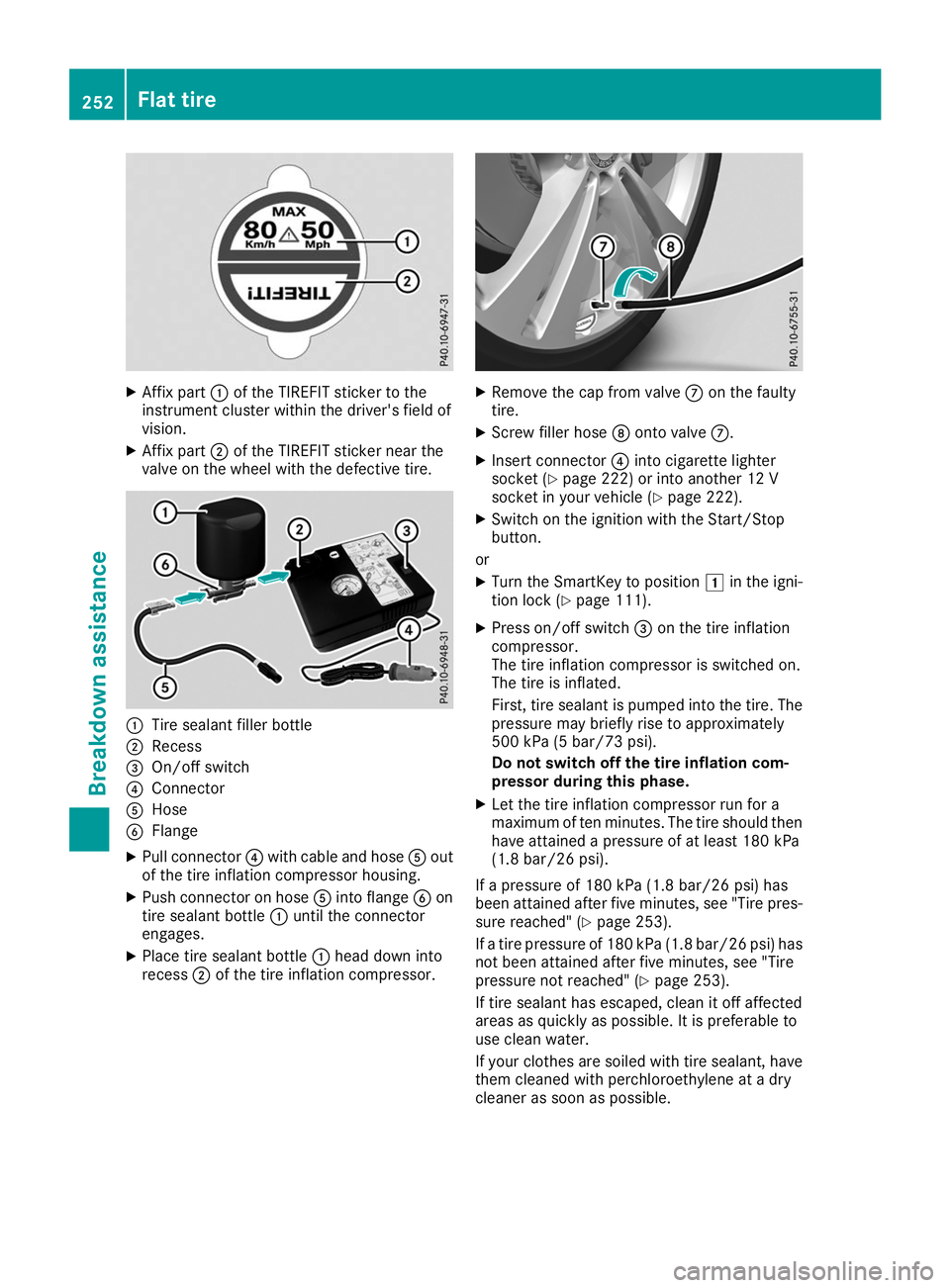
Affix part 0043of the TIREFIT sticker to the
instrument cluster within the driver's field of
vision.
X Affix part 0044of the TIREFIT sticker near the
valve on the wheel with the defective tire. 0043
Tire sealant filler bottle
0044 Recess
0087 On/off switch
0085 Connector
0083 Hose
0084 Flange
X Pull connector 0085with cable and hose 0083out
of the tire inflation compressor housing.
X Push connector on hose 0083into flange 0084on
tire sealant bottle 0043until the connector
engages.
X Place tire sealant bottle 0043head down into
recess 0044of the tire inflation compressor. X
Remove the cap from valve 006Bon the faulty
tire.
X Screw filler hose 006Conto valve 006B.
X Insert connector 0085into cigarette lighter
socket (Y page 222) or into another 12 V
socket in your vehicle (Y page 222).
X Switch on the ignition with the Start/Stop
button.
or X Turn the SmartKey to position 0047in the igni-
tion lock (Y page 111).
X Press on/off switch 0087on the tire inflation
compressor.
The tire inflation compressor is switched on.
The tire is inflated.
First, tire sealant is pumped into the tire. The
pressure may briefly rise to approximately
500 kPa (5 bar/73 psi).
Do not switch off the tire inflation com-
pressor during this phase.
X Let the tire inflation compressor run for a
maximum of ten minutes. The tire should then have attained a pressure of at least 180 kPa
(1.8 bar/26 psi).
If a pressure of 180 kPa (1.8 ba r/26 psi) has
been at tained after five minutes, see "Tire pres-
sure reached" (Y page 253).
If a tire pressure of 180 kPa (1.8 bar/26 psi) has not been attained after five minutes, see "Tire
pressure not reached" (Y page 253).
If tire sealant has escaped, clean it off affected
areas as quickly as possible. It is preferable to
use clean water.
If your clothes are soiled with tire sealant, have them cleaned with perchloroethylene at a dry
cleaner as soon as possible. 252
Flat tireBreakdown assistance
Page 261 of 298
!
Secure the tow rope or tow bar to the towing
eye only. Otherwise, the vehicle could
become damaged.
! When Active Brake Assist, Active Distance
Assist DISTRONIC or the HOLD function is
activated, the vehicle brakes automatically in
certain situations.
To avoid damage to the vehicle, deactivate
these systems in the following or similar sit-
uations:
R when towing the vehicle
R in the car wash
! Do not use the towing eyes for recovery pur-
poses as this could damage the vehicle. If in
doubt, recover the vehicle with a crane.
! When towing, pull away slowly and
smoothly. If the tractive power is too high, the
vehicles could be damaged.
! Shift the automatic transmission to position
005C and do not open the driver's or front-
passenger door when towing the vehicle
away. Otherwise, the automatic transmission may shift to position 005Dwhich can cause
damage to both vehicles.
! Do not tow with sling-type equipment. This
could damage the vehicle.
! You may tow the vehicle for a maximum dis-
tance of 30 miles (50 kilometers). A towing
speed of 30 mph (50 km/h) must not be
exceeded.
For towing distances over 30 miles
(50 kilometers), the entire vehicle must be
raised and transported.
! Observe the transmission fluid temperature
(AMG menu) in the on-board computer when
towing. The transmission oil temperature
must not exceed 250 ‡ (120 †). If this
occurs, you must stop towing immediately.
! Tow-starting the vehicle is not permitted.
The transmission may otherwise be damaged.
Also observe the following notes:
R If the engine does not start, try jump-starting
it (Y page 256). Tow-starting the vehicle is not
permitted.
R If it is not possible to jump-start the vehicle,
have it transported to the nearest qualified
specialist workshop, e.g. an authorized
Mercedes-Benz Service Center. If the vehicle can no longer be driven because of
an accident or breakdown, you have the follow- ing options:
R Transporting the vehicle.
As a rule, you should have the vehicle trans-
ported.
R Towing the vehicle with a tow rope or tow bar.
Only tow the vehicle in exceptional cases. The
engine must be running if you tow the vehicle with a tow rope or tow bar.
If the vehicle has suffered transmission damage, have it transported on a transporter or trailer.
Observe the display messages in the instrument
cluster.
The battery must be connected and charged.
Otherwise, you:
R will not be able to switch on the ignition with
the Start/Stop button
R cannot start the engine
R cannot release the electric parking brake.
R cannot shift the automatic transmission to
position 005C
Disarm the automatic locking feature before the vehicle is towed (Y page 73). You could other-
wise be locked out when pushing or towing the
vehicle. Permitted towing methods
Mercedes-Benz recommends transporting your
vehicle in the case of a breakdown, rather than
towing it away.
When towing away, use a towing rope or a tow-
ing bar with both axles on the ground. Do not use any tow bar systems. Installing/removing the towing eye
Installing the towing eye The bracket for the screw-in towing eye is
behind the radiator trim.
X Remove the towing eye from the vehicle tool
kit (Y page 249). Towing and tow-starting
259Breakdown assistance Z
Page 282 of 298
Speed rating
The speed rating is part of the tire identification. It specifies the speed range for which the tire is
approved.
GVW (Gross Vehicle Weight)
The gross vehicle weight includes the weight of the vehicle with fuel, tools, the spare wheel,
accessories installed, vehicle occupants, lug-
gage and the drawbar noseweight if applicable.
The gross vehicle weight must not exceed the
gross vehicle weight rating GVWR as specified
on the vehicle identification plate on the B-pillar
on the driver's side.
GVWR (Gross Vehicle Weight Rating)
The GVWR is the maximum permitted gross
weight of the fully laden vehicle (weight of the
vehicle including all accessories, vehicle occu-
pants, fuel, luggage and the drawbar nose-
weight if applicable). The gross vehicle weight
rating is specified on the vehicle identification
plate on the B-pillar on the driver's side.
Maximum loaded vehicle weight
The maximum weight is the sum of:
R the curb weight of the vehicle
R the weight of the accessories
R the load limit
R the weight of the factory installed optional
equipment
Kilopascal (kPa) Metric unit for tire pressure. 6.9 kPa corre-
sponds to 1 psi. Another unit for tire pressure is
bar. 100 kilopascals (kPa) are the equivalent of
1 bar.
Load index
In addition to the load-bearing index, the load
index may also be imprinted on the sidewall of
the tire. This specifies the load-bearing capacityof the tire more precisely.
Curb weight The weight of a vehicle with standard equipment
including the maximum capacity of fuel, oil and
coolant. It also includes the air-conditioning sys- tem and optional equipment if these are instal-
led in the vehicle, but does not include passen-
gers or luggage. Maximum load rating
The maximum tire load is the maximum permis- sible weight in kilograms or lbs for which a tire is
approved.
Maximum permissible tire pressure Maximum permissible tire pressure for one tire.
Maximum load on one tire Maximum load on one tire. This is calculated by
dividing the maximum axle load of one axle by
two.
PSI (pounds per square inch)
A standard unit of measure for tire pressure.
Aspect ratioRelationship between tire height and tire width
in percent.
Tire pressure
This is pressure inside the tire applying an out-
ward force to each square inch of the tire's sur-
face. The tire pressure is specified in pounds per
square inch (psi), in kilopascal (kPa) or in bar.
The tire pressure should only be corrected when
the tires are cold.
Cold tire pressure
The tires are cold:
R if the vehicle has been parked with the tires
out of direct sunlight for at least three hours
and
R if the vehicle has not been driven further than
1 mile (1.6 km)
Tread The part of the tire that comes into contact with
the road.
Bead
The tire bead ensures that the tire sits securely
on the wheel. There are several steel wires in the bead to prevent the tire from coming loose from
the wheel rim.
Sidewall
The part of the tire between the tread and the
bead. 280
All about wheels and tiresWheels and tires
Page 284 of 298
An arrow on the sidewall of the tire indicates its
correct direction of rotation. Storing wheels
Store wheels that are not being used in a cool,
dry and preferably dark place. Protect the tires
from oil, grease, gasoline and diesel. Mounting a wheel
Preparing the vehicle X
Stop the vehicle on solid, non-slippery and
level ground.
X Apply the electric parking brake manually.
X Bring the front wheels into the straight-ahead
position.
X Shift the transmission to position 005D.
X Switch off the engine.
X With KEYLESS-GO start function or vehi-
cles with KEYLESS-GO:
open the driver's
door.
The vehicle electronics are now in key posi-
tion 0092. This is the same as the SmartKey
having been removed.
or X Remove the SmartKey from the ignition lock.
X If included in the vehicle equipment, remove
the tire-change tool kit from the vehicle.
X Safeguard the vehicle against rolling away.
Securing the vehicle to prevent it from
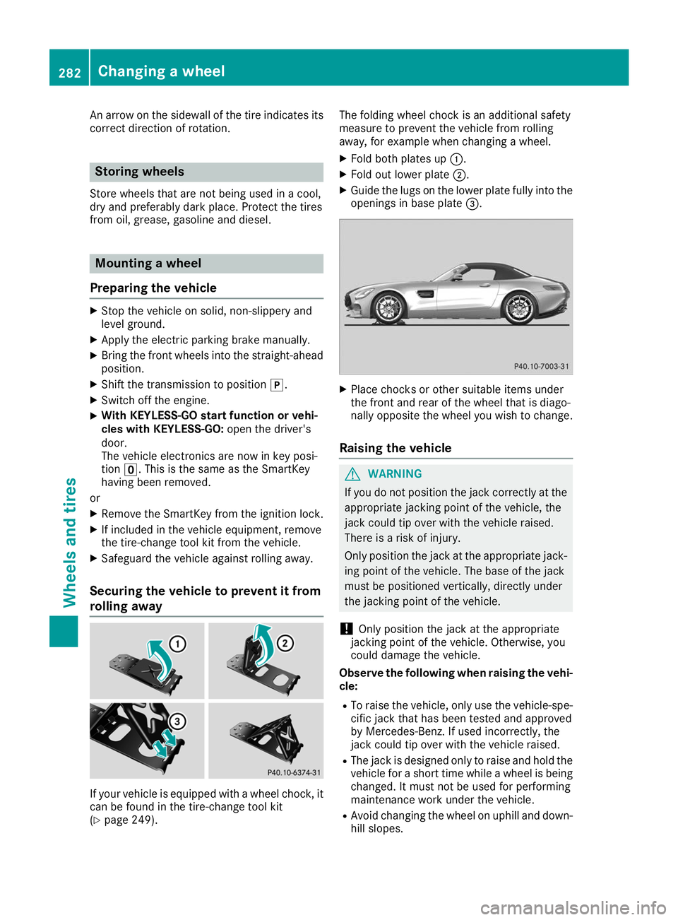
rolling away If your vehicle is equipped with a wheel chock, it
can be found in the tire-change tool kit
(Y page 249). The folding wheel chock is an additional safety
measure to prevent the vehicle from rolling
away, for example when changing a wheel.
X Fold both plates up 0043.
X Fold out lower plate 0044.
X Guide the lugs on the lower plate fully into the
openings in base plate 0087. X
Place chocks or other suitable items under
the front and rear of the wheel that is diago-
nally opposite the wheel you wish to change.
Raising the vehicle G
WARNING
If you do not position the jack correctly at the appropriate jacking point of the vehicle, the
jack could tip over with the vehicle raised.
There is a risk of injury.
Only position the jack at the appropriate jack-
ing point of the vehicle. The base of the jack
must be positioned vertically, directly under
the jacking point of the vehicle.
! Only position the jack at the appropriate
jacking point of the vehicle. Otherwise, you
could damage the vehicle.
Observe the following when raising the vehi- cle:
R To raise the vehicle, only use the vehicle-spe-
cific jack that has been tested and approved
by Mercedes-Benz. If used incorrectly, the
jack could tip over with the vehicle raised.
R The jack is designed only to raise and hold the
vehicle for a short time while a wheel is being
changed. It must not be used for performing
maintenance work under the vehicle.
R Avoid changing the wheel on uphill and down-
hill slopes. 282
Changing a wheelWheels and tires
Page 285 of 298
R
Before raising the vehicle, secure it from roll-
ing away by applying the parking brake and
inserting wheel chocks. Do not disengage the parking brake while the vehicle is raised.
R The jack must be placed on a firm, flat and
non-slip surface. On a loose surface, a large,
flat, load-bearing underlay must be used. On a slippery surface, a non-slip underlay must be
used, e.g. rubber mats.
R Do not use wooden blocks or similar objects
as a jack underlay. Otherwise, the jack will not
be able to achieve its load-bearing capacity
due to the restricted height.
R Make sure that the distance between the
underside of the tires and the ground does not
exceed 1.2 in (3 cm).
R Do not place your hands or feet under the
raised vehicle.
R Do not lie under the vehicle.
R Do not start the engine when the vehicle is
raised.
R Do not open or close a door or the trunk lid
when the vehicle is raised.
R Make sure that no persons are present in the
vehicle when the vehicle is raised.
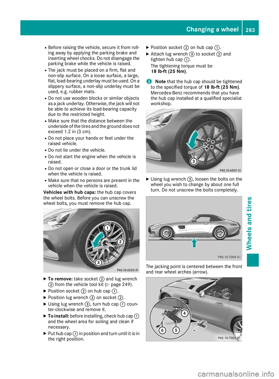
Vehicles with hub caps: the hub cap covers
the wheel bolts. Before you can unscrew the
wheel bolts, you must remove the hub cap. X
To remove: take socket0044and lug wrench
0087 from the vehicle tool kit (Y page 249).
X Position socket 0044on hub cap 0043.
X Position lug wrench 0087on socket 0044.
X Using lug wrench 0087, turn hub cap0043coun-
ter-clockwise and remove it.
X To install: before installing, check hub cap 0043
and the wheel area for soiling and clean if
necessary.
X Put hub cap 0043in position and turn until it is in
the right position. X
Position socket 0044on hub cap 0043.
X Attach lug wrench 0087to socket 0044and
tighten hub cap 0043.
The tightening torque must be
18 lb-ft (25 Nm).
i Note
that the hub cap should be tightened
to the specified torque of 18 lb-ft (25 Nm).
Mercedes-Benz recommends that you have
the hub cap installed at a qualified specialist
workshop. X
Using lug wrench 0087, loosen the bolts on the
wheel you wish to change by about one full
turn. Do not unscrew the bolts completely. The jacking point is centered between the front
and rear wheel arches (arrow). Changing a wheel
283Wheels and tires Z
Page 286 of 298
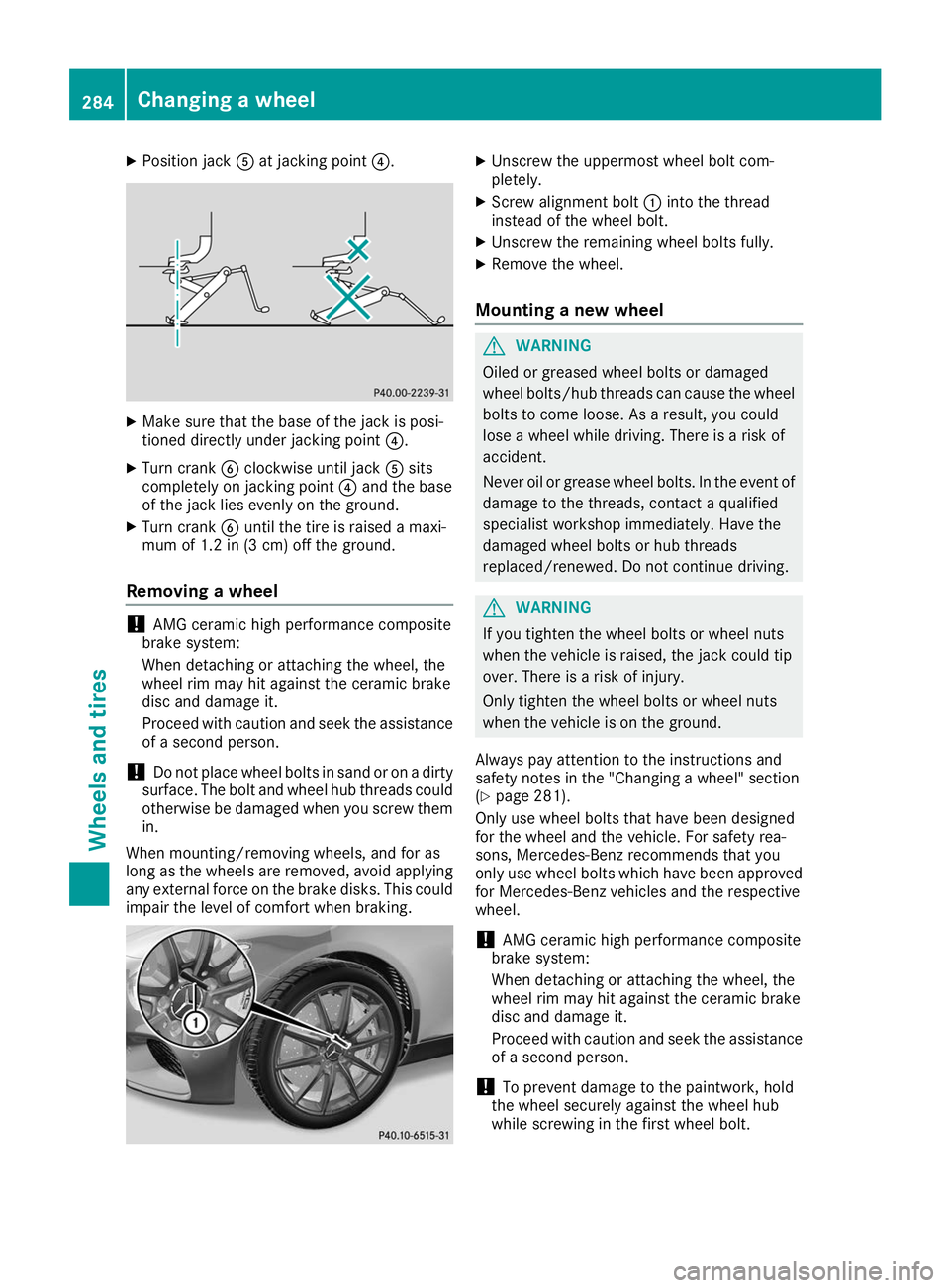
X
Position jack 0083at jacking point 0085. X
Make sure that the base of the jack is posi-
tioned directly under jacking point 0085.
X Turn crank 0084clockwise until jack 0083sits
completely on jacking point 0085and the base
of the jack lies evenly on the ground.
X Turn crank 0084until the tire is raised a maxi-
mum of 1.2 in (3 cm) off the ground.
Removing a wheel !
AMG ceramic high performance composite
brake system:
When detaching or attaching the wheel, the
wheel rim may hit against the ceramic brake
disc and damage it.
Proceed with caution and seek the assistance of a second person.
! Do not place wheel bolts in sand or on a dirty
surface. The bolt and wheel hub threads could
otherwise be damaged when you screw them in.
When mounting/removing wheels, and for as
long as the wheels are removed, avoid applying any external force on the brake disks. This could
impair the level of comfort when braking. X
Unscrew the uppermost wheel bolt com-
pletely.
X Screw alignment bolt 0043into the thread
instead of the wheel bolt.
X Unscrew the remaining wheel bolts fully.
X Remove the wheel.
Mounting a new wheel G
WARNING
Oiled or greased wheel bolts or damaged
wheel bolts/hub threads can cause the wheel bolts to come loose. As a result, you could
lose a wheel while driving. There is a risk of
accident.
Never oil or grease wheel bolts. In the event ofdamage to the threads, contact a qualified
specialist workshop immediately. Have the
damaged wheel bolts or hub threads
replaced/renewed. Do not continue driving. G
WARNING
If you tighten the wheel bolts or wheel nuts
when the vehicle is raised, the jack could tip
over. There is a risk of injury.
Only tighten the wheel bolts or wheel nuts
when the vehicle is on the ground.
Always pay attention to the instructions and
safety notes in the "Changing a wheel" section
(Y page 281).
Only use wheel bolts that have been designed
for the wheel and the vehicle. For safety rea-
sons, Mercedes-Benz recommends that you
only use wheel bolts which have been approved for Mercedes-Benz vehicles and the respective
wheel.
! AMG ceramic high performance composite
brake system:
When detaching or attaching the wheel, the
wheel rim may hit against the ceramic brake
disc and damage it.
Proceed with caution and seek the assistance
of a second person.
! To prevent damage to the paintwork, hold
the wheel securely against the wheel hub
while screwing in the first wheel bolt. 284
Changing a wheelWheels and tires
Page 291 of 298
Service products and filling capaci-
ties
Important safety notes
G
WARNING
Service products may be poisonous and haz-
ardous to health. There is a risk of injury.
Comply with instructions on the use, storage
and disposal of service products on the labels of the respective original containers. Always
store service products sealed in their original containers. Always keep service products out
of the reach of children. H
Environmental note
Dispose of service products in an environ-
mentally responsible manner.
Service products include the following: R Fuels
R Lubricants (e.g. engine oil, transmission oil)
R Coolant
R Brake fluid
R Windshield washer fluid
R Climate control system refrigerant
Components and service products must match.
Only use products recommended by Mercedes-
Benz. Damage which is caused by the use of
products which have not been recommended is
not covered by the Mercedes-Benz warranty or
goodwill gestures. They are listed in this
Mercedes-Benz Operator's Manual in the appro- priate section.
Information on tested and approved products
can be obtained at an authorized Mercedes-
Benz Center or on the Internet at
http://bevo.mercedes-benz.com.
You can recognize service products approved by Mercedes-Benz by the following inscription on
the containers:
R MB-Freigabe (e.g. MB-Freigabe 229.51)
R MB-Approval (e.g. MB-Approval 229.51)
Other designations or recommendations indi-
cate a level of quality or a specification in
accordance with an MB Sheet Number (e.g. MB
229.5). They have not necessarily been
approved by Mercedes-Benz. Other identifications, for example:
R 0 W-30
R 5 W-30
R 5 W-40 Fuel
Important safety notes G
WARNING
Fuel is highly flammable. Risk of fire and
explosion by improper handling of fuel.
You must avoid fire, open flames, smoking
and creating sparks. Switch off the ignition
before refueling and, if present, switch off the auxiliary heating. G
WARNING
Fuel is poisonous and hazardous to health.
There is a risk of injury.
You must make sure that fuel does not come into contact with your skin, eyes or clothing
and that it is not swallowed. Do not inhale fuel
vapors. Keep fuel away from children.
If you or others come into contact with fuel,
observe the following:
R Wash away fuel from skin immediately
using soap and water.
R If fuel comes into contact with your eyes,
immediately rinse them thoroughly with
clean water. Seek medical assistance with-
out delay.
R If fuel is swallowed, seek medical assis-
tance without delay. Do not induce vomit-
ing.
R Immediately change out of clothing which
has come into contact with fuel.
Tank capacity Model Total capacity
All models
19.8 US gal
(75.0 l) Service products and filling capacities
289Technical data Z