2019 MERCEDES-BENZ AMG GT ROADSTER lock
[x] Cancel search: lockPage 263 of 298
X
Turn the SmartKey to key position 0092in the
ignition lock and remove it.
X Secure the vehicle. Tow-starting (emergency engine
starting)
! Vehicles with automatic transmission must
not be tow-started. You could otherwise dam- age the automatic transmission.
i You can find information on "Jump-starting"
under (Y page 256). Fuses
Important safety notes
G
WARNING
If you manipulate or bridge a faulty fuse or if
you replace it with a fuse with a higher amper- age, the electric cables could be overloaded.
This could result in a fire. There is a risk of an
accident and injury.
Always replace faulty fuses with the specified
new fuses having the correct amperage.
Blown fuses must be replaced with fuses of the
same rating, which you can recognize by the
color and value. The fuse ratings are listed in the
fuse allocation chart.
The fuse allocation chart is on the fuse box in the trunk (Y page 262).
If a newly inserted fuse also blows, have the
cause traced and rectified at a qualified special-
ist workshop, e.g. an authorized Mercedes-Benz Center.
! Only use fuses that have been approved for
Mercedes-Benz vehicles and which have the
correct fuse rating for the system concerned.
Otherwise, components or systems could be
damaged.
! Make sure that no moisture can enter the
fuse box when the cover is open.
! When closing the cover, make sure that it is
lying correctly on the fuse box. Moisture seep-
ing in or dirt could otherwise impair the oper- ation of the fuses. The fuses in your vehicle serve to close down
faulty circuits. If a fuse blows, all the compo-
nents on the circuit and their functions stop
operating. Before changing a fuse
X Switch off the engine.
X Switch off all electrical consumers.
X Open the driver's door.
The on-board electronics are now in key posi-
tion 0092. This is the same as the key having
been removed.
or, if the SmartKey is inserted in the ignition
lock: X Remove the SmartKey from the ignition lock.
X Secure the vehicle against rolling away
(Y page 127).
All indicator lamps in the instrument cluster
must be off. Fuse box in the front passenger foot-
well
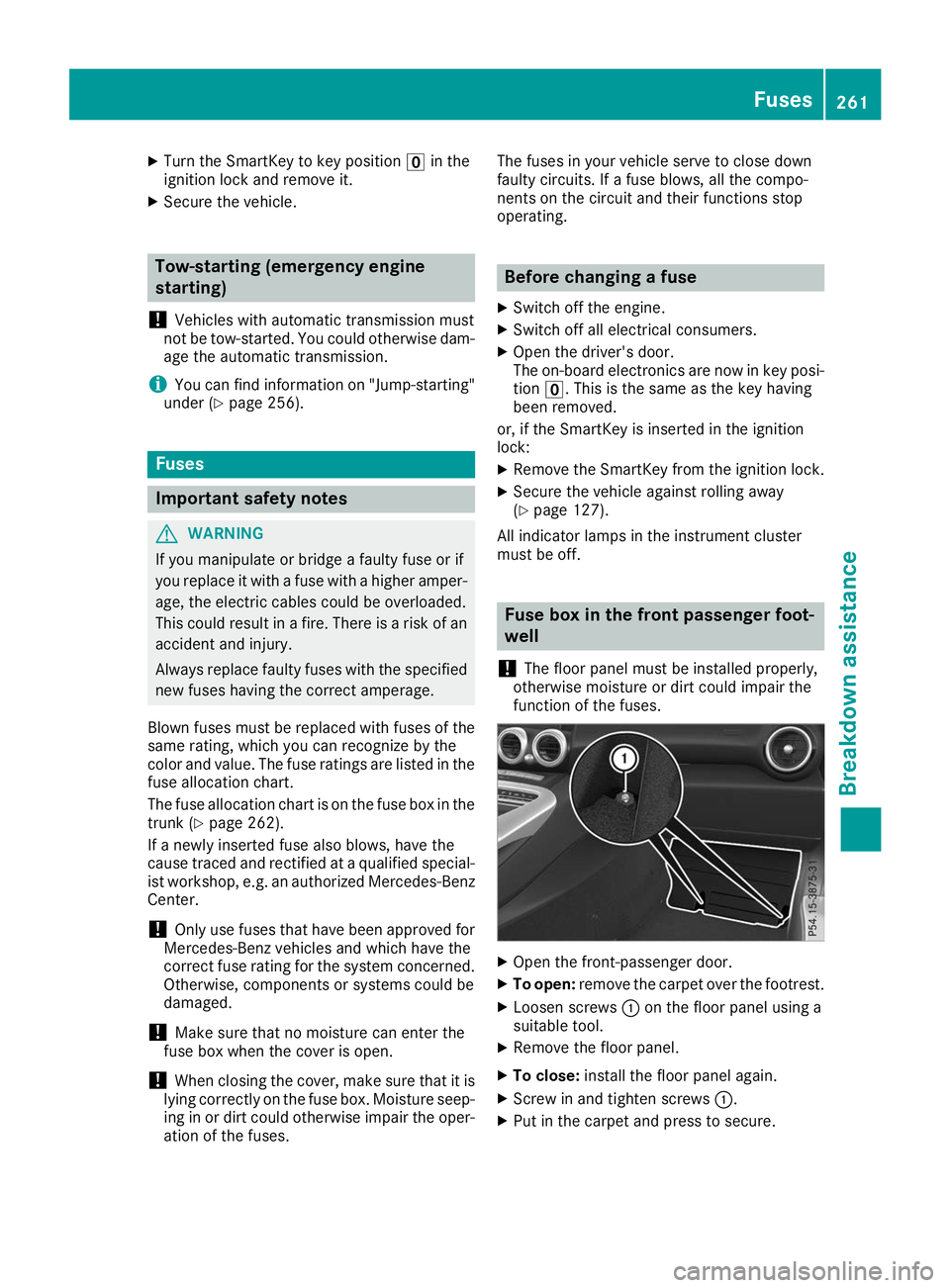
! The floor panel must be installed properly,
otherwise moisture or dirt could impair the
function of the fuses. X
Open the front-passenger door.
X To open: remove the carpet over the footrest.
X Loosen screws 0043on the floor panel using a
suitable tool.
X Remove the floor panel.
X To close: install the floor panel again.
X Screw in and tighten screws 0043.
X Put in the carpet and press to secure. Fuses
261Breakdown assistance Z
Page 266 of 298
i
Different driving styles may lead to high tire
wear and the tires may reach the minimum
tire tread depth after only a short time. Regular checking of wheels and tires
G
WARNING
Damaged tires can cause tire inflation pres-
sure loss. As a result, you could lose control of your vehicle. There is a risk of accident.
Check the tires regularly for signs of damage
and replace any damaged tires immediately.
Check wheels and tires for damage at least once a month. Check wheels and tires after driving
off-road or on rough roads. Damaged wheels
can cause a loss of tire pressure.
Pay particular attention to damage such as:
R Cuts in the tires
R Punctures in the tires
R Tears in the tires
R Bulges on tires
R Deformation or severe corrosion on wheels
Regularly check the tire tread depth and the
condition of the tread across the whole width of
all tires (Y page 264). If necessary, turn the
front wheels to full lock in order to inspect the
inner side of the tire surface.
All wheels must have a valve cap to protect the
valve against dirt and moisture. Do not mount
anything onto the valve other than the standard valve cap or other valve caps approved by
Mercedes-Benz for your vehicle. Do not use any other valve caps or systems, e.g. tire pressure
monitoring systems.
Regularly check the pressure of all the tires par- ticularly prior to long trips. Adjust the tire pres-
sure as necessary (Y page 266).
The service life of tires depends, among other
things, on the following factors:
R Driving style
R Tire pressure
R Distance covered Notes on tire tread
G
WARNING
Insufficient tire tread will reduce tire traction.
The tire is no longer able to dissipate water.
This means that on wet road surfaces, the risk of hydroplaning increases, in particular where speed is not adapted to suit the driving con-
ditions. There is a risk of accident.
If the tire pressure is too high or too low, tires
may exhibit different levels of wear at differ-
ent locations on the tire tread. Thus, you
should regularly check the tread depth and
the condition of the tread across the entire
width of all tires.
Minimum tire tread depth for:
R Summer tires: 00CEin (3 mm)
R M+S tires: 00CFin (4 mm)
For safety reasons, replace the tires before
the legally prescribed limit for the minimum
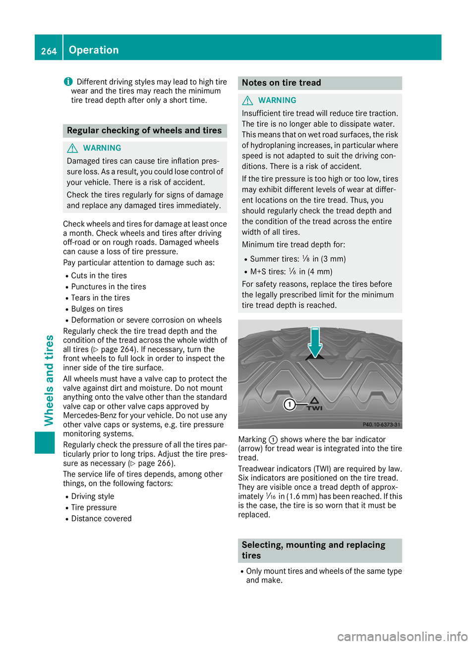
tire tread depth is reached. Marking
0043shows where the bar indicator
(arrow) for tread wear is integrated into the tire
tread.
Treadwear indicators (TWI) are required by law. Six indicators are positioned on the tire tread.
They are visible once a tread depth of approx-
imately 00CDin (1.6 mm) has been reached. If this
is the case, the tire is so worn that it must be
replaced. Selecting, mounting and replacing
tires
R Only mount tires and wheels of the same type
and make. 264
OperationWheels and tires
Page 284 of 298
An arrow on the sidewall of the tire indicates its
correct direction of rotation. Storing wheels
Store wheels that are not being used in a cool,
dry and preferably dark place. Protect the tires
from oil, grease, gasoline and diesel. Mounting a wheel
Preparing the vehicle X
Stop the vehicle on solid, non-slippery and
level ground.
X Apply the electric parking brake manually.
X Bring the front wheels into the straight-ahead
position.
X Shift the transmission to position 005D.
X Switch off the engine.
X With KEYLESS-GO start function or vehi-
cles with KEYLESS-GO:
open the driver's
door.
The vehicle electronics are now in key posi-
tion 0092. This is the same as the SmartKey
having been removed.
or X Remove the SmartKey from the ignition lock.
X If included in the vehicle equipment, remove
the tire-change tool kit from the vehicle.
X Safeguard the vehicle against rolling away.
Securing the vehicle to prevent it from
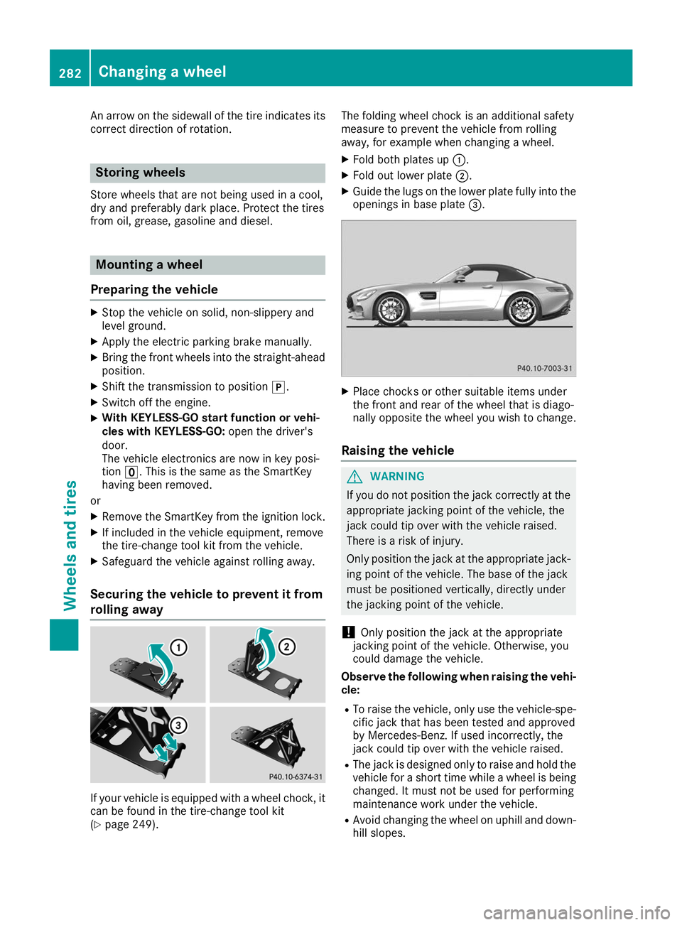
rolling away If your vehicle is equipped with a wheel chock, it
can be found in the tire-change tool kit
(Y page 249). The folding wheel chock is an additional safety
measure to prevent the vehicle from rolling
away, for example when changing a wheel.
X Fold both plates up 0043.
X Fold out lower plate 0044.
X Guide the lugs on the lower plate fully into the
openings in base plate 0087. X
Place chocks or other suitable items under
the front and rear of the wheel that is diago-
nally opposite the wheel you wish to change.
Raising the vehicle G
WARNING
If you do not position the jack correctly at the appropriate jacking point of the vehicle, the
jack could tip over with the vehicle raised.
There is a risk of injury.
Only position the jack at the appropriate jack-
ing point of the vehicle. The base of the jack
must be positioned vertically, directly under
the jacking point of the vehicle.
! Only position the jack at the appropriate
jacking point of the vehicle. Otherwise, you
could damage the vehicle.
Observe the following when raising the vehi- cle:
R To raise the vehicle, only use the vehicle-spe-
cific jack that has been tested and approved
by Mercedes-Benz. If used incorrectly, the
jack could tip over with the vehicle raised.
R The jack is designed only to raise and hold the
vehicle for a short time while a wheel is being
changed. It must not be used for performing
maintenance work under the vehicle.
R Avoid changing the wheel on uphill and down-
hill slopes. 282
Changing a wheelWheels and tires
Page 285 of 298
R
Before raising the vehicle, secure it from roll-
ing away by applying the parking brake and
inserting wheel chocks. Do not disengage the parking brake while the vehicle is raised.
R The jack must be placed on a firm, flat and
non-slip surface. On a loose surface, a large,
flat, load-bearing underlay must be used. On a slippery surface, a non-slip underlay must be
used, e.g. rubber mats.
R Do not use wooden blocks or similar objects
as a jack underlay. Otherwise, the jack will not
be able to achieve its load-bearing capacity
due to the restricted height.
R Make sure that the distance between the
underside of the tires and the ground does not
exceed 1.2 in (3 cm).
R Do not place your hands or feet under the
raised vehicle.
R Do not lie under the vehicle.
R Do not start the engine when the vehicle is
raised.
R Do not open or close a door or the trunk lid
when the vehicle is raised.
R Make sure that no persons are present in the
vehicle when the vehicle is raised.
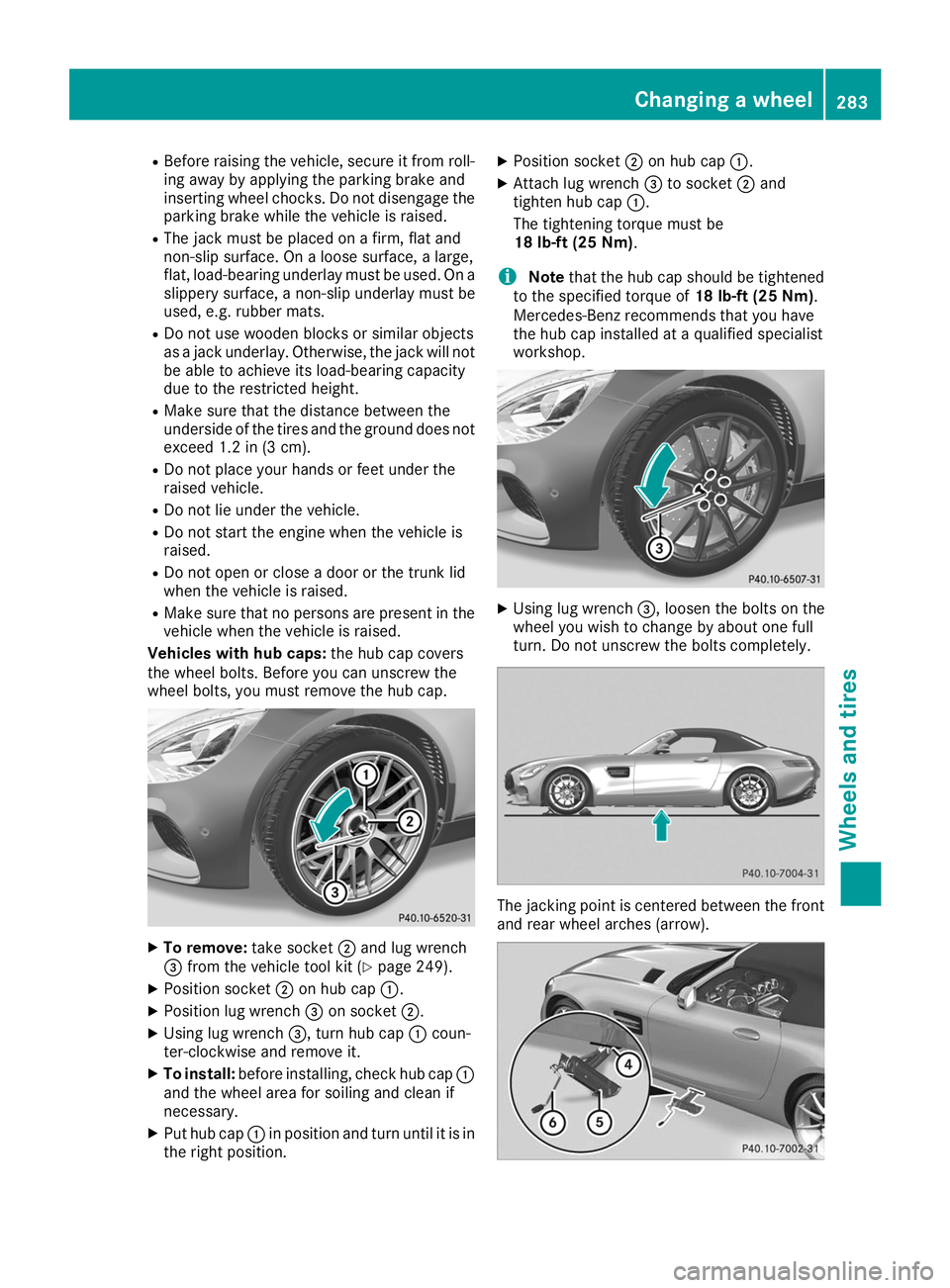
Vehicles with hub caps: the hub cap covers
the wheel bolts. Before you can unscrew the
wheel bolts, you must remove the hub cap. X
To remove: take socket0044and lug wrench
0087 from the vehicle tool kit (Y page 249).
X Position socket 0044on hub cap 0043.
X Position lug wrench 0087on socket 0044.
X Using lug wrench 0087, turn hub cap0043coun-
ter-clockwise and remove it.
X To install: before installing, check hub cap 0043
and the wheel area for soiling and clean if
necessary.
X Put hub cap 0043in position and turn until it is in
the right position. X
Position socket 0044on hub cap 0043.
X Attach lug wrench 0087to socket 0044and
tighten hub cap 0043.
The tightening torque must be
18 lb-ft (25 Nm).
i Note
that the hub cap should be tightened
to the specified torque of 18 lb-ft (25 Nm).
Mercedes-Benz recommends that you have
the hub cap installed at a qualified specialist
workshop. X
Using lug wrench 0087, loosen the bolts on the
wheel you wish to change by about one full
turn. Do not unscrew the bolts completely. The jacking point is centered between the front
and rear wheel arches (arrow). Changing a wheel
283Wheels and tires Z
Page 286 of 298
X
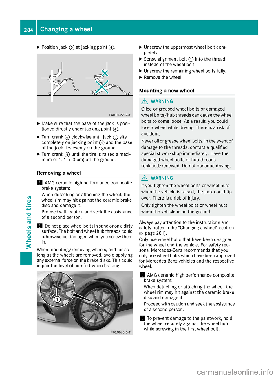
Position jack 0083at jacking point 0085. X
Make sure that the base of the jack is posi-
tioned directly under jacking point 0085.
X Turn crank 0084clockwise until jack 0083sits
completely on jacking point 0085and the base
of the jack lies evenly on the ground.
X Turn crank 0084until the tire is raised a maxi-
mum of 1.2 in (3 cm) off the ground.
Removing a wheel !
AMG ceramic high performance composite
brake system:
When detaching or attaching the wheel, the
wheel rim may hit against the ceramic brake
disc and damage it.
Proceed with caution and seek the assistance of a second person.
! Do not place wheel bolts in sand or on a dirty
surface. The bolt and wheel hub threads could
otherwise be damaged when you screw them in.
When mounting/removing wheels, and for as
long as the wheels are removed, avoid applying any external force on the brake disks. This could
impair the level of comfort when braking. X
Unscrew the uppermost wheel bolt com-
pletely.
X Screw alignment bolt 0043into the thread
instead of the wheel bolt.
X Unscrew the remaining wheel bolts fully.
X Remove the wheel.
Mounting a new wheel G
WARNING
Oiled or greased wheel bolts or damaged
wheel bolts/hub threads can cause the wheel bolts to come loose. As a result, you could
lose a wheel while driving. There is a risk of
accident.
Never oil or grease wheel bolts. In the event ofdamage to the threads, contact a qualified
specialist workshop immediately. Have the
damaged wheel bolts or hub threads
replaced/renewed. Do not continue driving. G
WARNING
If you tighten the wheel bolts or wheel nuts
when the vehicle is raised, the jack could tip
over. There is a risk of injury.
Only tighten the wheel bolts or wheel nuts
when the vehicle is on the ground.
Always pay attention to the instructions and
safety notes in the "Changing a wheel" section
(Y page 281).
Only use wheel bolts that have been designed
for the wheel and the vehicle. For safety rea-
sons, Mercedes-Benz recommends that you
only use wheel bolts which have been approved for Mercedes-Benz vehicles and the respective
wheel.
! AMG ceramic high performance composite
brake system:
When detaching or attaching the wheel, the
wheel rim may hit against the ceramic brake
disc and damage it.
Proceed with caution and seek the assistance
of a second person.
! To prevent damage to the paintwork, hold
the wheel securely against the wheel hub
while screwing in the first wheel bolt. 284
Changing a wheelWheels and tires
Page 287 of 298
0043
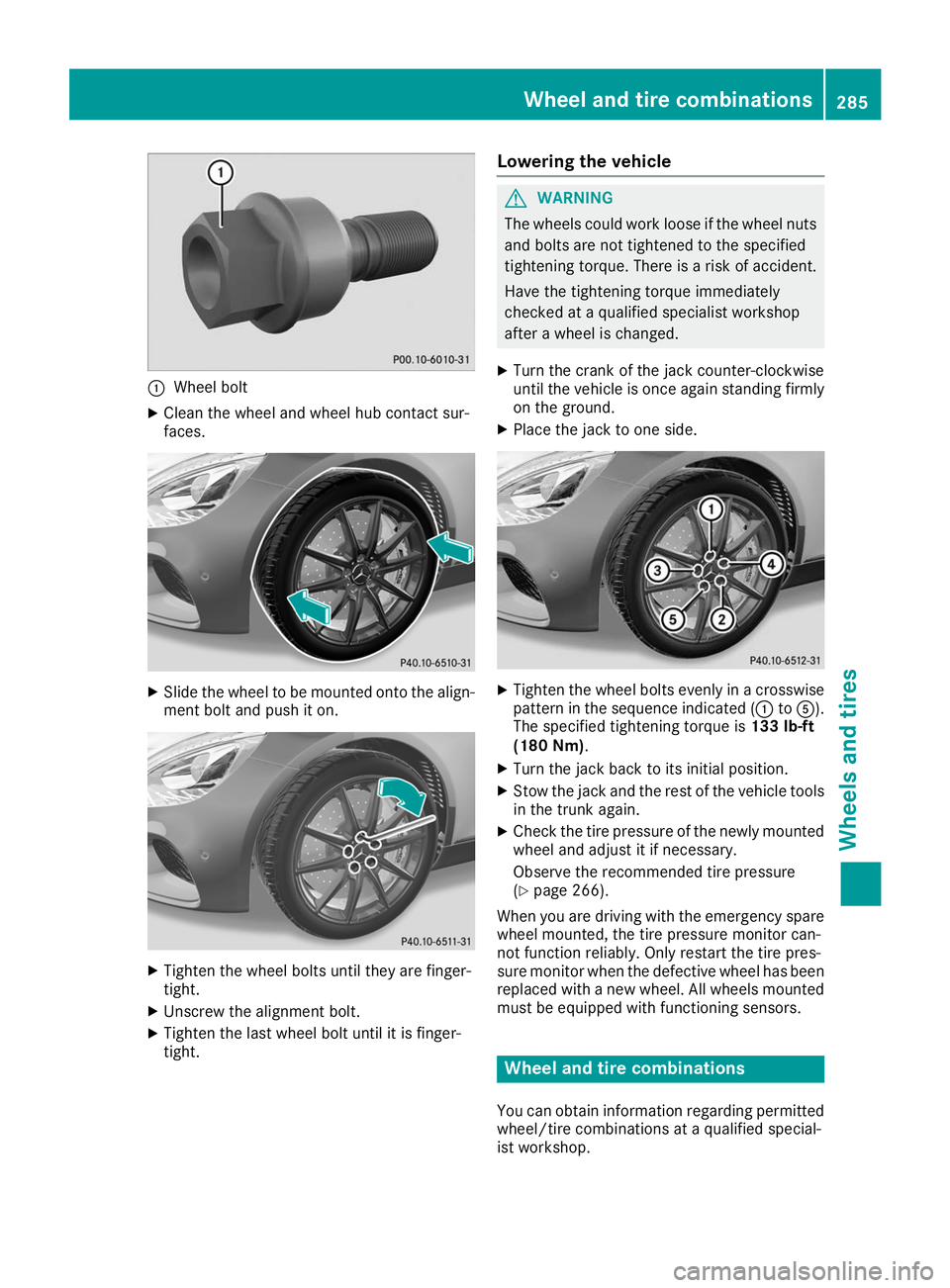
Wheel bolt
X Clean the wheel and wheel hub contact sur-
faces. X
Slide the wheel to be mounted onto the align-
ment bolt and push it on. X
Tighten the wheel bolts until they are finger-
tight.
X Unscrew the alignment bolt.
X Tighten the last wheel bolt until it is finger-
tight. Lowering the vehicle G
WARNING
The wheels could work loose if the wheel nuts and bolts are not tightened to the specified
tightening torque. There is a risk of accident.
Have the tightening torque immediately
checked at a qualified specialist workshop
after a wheel is changed.
X Turn the crank of the jack counter-clockwise
until the vehicle is once again standing firmly
on the ground.
X Place the jack to one side. X
Tighten the wheel bolts evenly in a crosswise
pattern in the sequence indicated (0043 to0083).
The specified tightening torque is 133 lb-ft
(180 Nm).
X Turn the jack back to its initial position.
X Stow the jack and the rest of the vehicle tools
in the trunk again.
X Check the tire pressure of the newly mounted
wheel and adjust it if necessary.
Observe the recommended tire pressure
(Y page 266).
When you are driving with the emergency spare
wheel mounted, the tire pressure monitor can-
not function reliably. Only restart the tire pres-
sure monitor when the defective wheel has been replaced with a new wheel. All wheels mounted
must be equipped with functioning sensors. Wheel and tire combinations
You can obtain information regarding permitted wheel/tire combinations at a qualified special-
ist workshop. Wheel and tire combinations
285Wheels and tires Z
Page 295 of 298
!
Only MB SummerFit and MB WinterFit
washer fluid should be mixed together. The
spray nozzles may otherwise become
blocked.
Do not use distilled or de-ionized water. Other-
wise, the level sensor may give a false reading.
At temperatures above freezing:
X Fill the washer fluid reservoir with a mixture of
water and windshield washer fluid, e.g. MB
SummerFit.
Add 1 part MB SummerFit to 100 parts water.
At temperatures below freezing:
X Fill the washer fluid reservoir with a mixture of
water and washer fluid, e.g. MB WinterFit.
For the correct mixing ratio refer to the infor-mation on the antifreeze reservoir.
i Add windshield washer fluid, e.g. MB Sum-
merFit or MB WinterFit, to the washer fluid all
year round. Climate control system refrigerant
Important safety notes The instruction label regarding the refrigerant
type used can be found on the radiator cross
member. Further information can be found in
the currently valid service information.
Service work, such as refilling with refrigerant or
replacing component parts, may only be carried out by a qualified specialist workshop. All appli-
cable regulations must be adhered to, SAE
standard J639 included.
Always have work on the climate control system
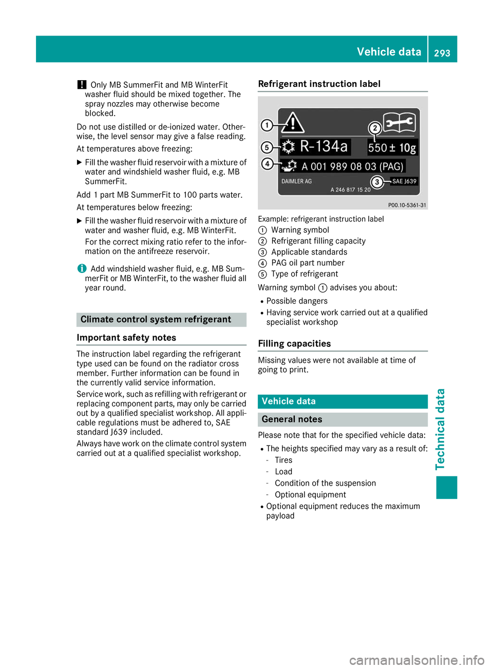
carried out at a qualified specialist workshop. Refrigerant instruction label Example: refrigerant instruction label
0043
Warning symbol
0044 Refrigerant filling capacity
0087 Applicable standards
0085 PAG oil part number
0083 Type of refrigerant
Warning symbol 0043advises you about:
R Possible dangers
R Having service work carried out at a qualified
specialist workshop
Filling capacities Missing values were not available at time of
going to print. Vehicle data
General notes
Please note that for the specified vehicle data:
R The heights specified may vary as a result of:
- Tires
- Load
- Condition of the suspension
- Optional equipment
R Optional equipment reduces the maximum
payload Vehicle data
293Technical data Z