2019 MASERATI LEVANTE tow
[x] Cancel search: towPage 69 of 436
present to occupant present the
system will repeat the warning
sequence.
The driver should instruct all other
occupants to fasten their seat belts.
If a front seat belt is unbuckled while
traveling at speeds greater than
5 mph (8 km/h), BeltAlert ®
will
provide both audio and visual
notification on the instrument cluster.
The front passenger seat BeltAlert ®
is
not active when the front passenger
seat is not occupied. BeltAlert ®
may
be triggered when an animal or heavy
object is on the front passenger seat.
It is recommended to restrain pets in
the rear seat, in pet harnesses or pet
carriers that are secured by seat belts,
and properly stow cargo.
Seat Belts and Pregnant
Women Seat belts should be worn by pregnant
women: the risk of injury in the event
of an accident is greatly reduced for
them and the unborn child if they are
wearing a seat belt. The best way to
protect the fetus is to protect the
mother.
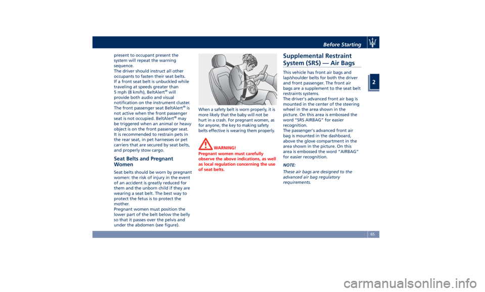
Pregnant women must position the
lower part of the belt below the belly
so that it passes over the pelvis and
under the abdomen (see figure). When a safety belt is worn properly, it is
more likely that the baby will not be
hurt in a crash. For pregnant women, as
for anyone, the key to making safety
belts effective is wearing them properly.
WARNING!
Pregnant women must carefully
observe the above indications, as well
as local regulation concerning the use
of seat belts.Supplemental Restraint
System (SRS) — Air Bags This vehicle has front air bags and
lap/shoulder belts for both the driver
and front passenger. The front air
bags are a supplement to the seat belt
restraints systems.
The driver's advanced front air bag is
mounted in the center of the steering
wheel in the area shown in the
picture. On this area is embossed the
word “SRS AIRBAG” for easier
recognition.
The passenger's advanced front air
bag is mounted in the dashboard,
above the glove compartment in the
area shown in the picture. On this
area is embossed the word “AIRBAG”
for easier recognition.
NOTE:
These air bags are designed to the
advanced air bag regulatory
requirements.Before Starting
2
65
Page 82 of 436
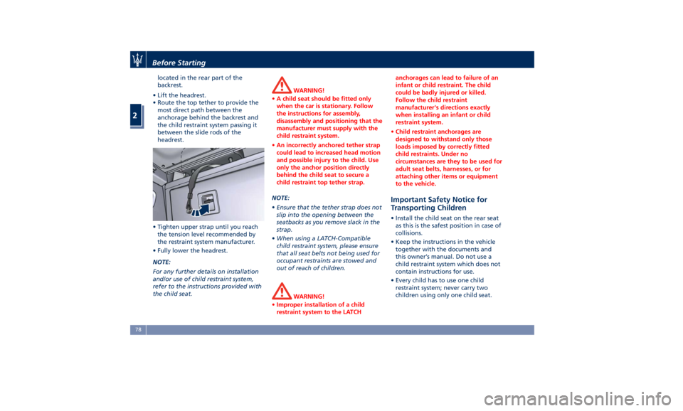
located in the rear part of the
backrest.
• Lift the headrest.
• Route the top tether to provide the
most direct path between the
anchorage behind the backrest and
the child restraint system passing it
between the slide rods of the
headrest.
• Tighten upper strap until you reach
the tension level recommended by
the restraint system manufacturer.
• Fully lower the headrest.
NOTE:
For any further details on installation
and/or use of child restraint system,
refer to the instructions provided with
the child seat. WARNING!
• A child seat should be fitted only
when the car is stationary. Follow
the instructions for assembly,
disassembly and positioning that the
manufacturer must supply with the
child restraint system.
• An incorrectly anchored tether strap
could lead to increased head motion
and possible injury to the child. Use
only the anchor position directly
behind the child seat to secure a
child restraint top tether strap.
NOTE:
• Ensure
that the tether strap does not
slip into the opening between the
seatbacks as you remove slack in the
strap.
• When using a LATCH-Compatible
child restraint system, please ensure
that all seat belts not being used for
occupant restraints are stowed and
out of reach of children.
WARNING!
• Improper installation of a child
restraint system to the LATCH anchorages can lead to failure of an
infant or child restraint. The child
could be badly injured or killed.
Follow the child restraint
manufacturer's directions exactly
when installing an infant or child
restraint system.
• Child restraint anchorages are
designed to withstand only those
loads imposed by correctly fitted
child restraints. Under no
circumstances are they to be used for
adult seat belts, harnesses, or for
attaching other items or equipment
to the vehicle.
Important Safety Notice for
Transporting Children • Install the child seat on the rear seat
as this is the safest position in case of
collisions.
• Keep the instructions in the vehicle
together with the documents and
this owner’s manual. Do not use a
child restraint system which does not
contain instructions for use.
• Every child has to use one child
restraint system; never carry two
children using only one child seat.Before Starting
2
78
Page 85 of 436
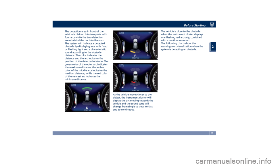
The detection area in front of the
vehicle is divided into two parts with
four arcs while the two detection
areas behind the car into five arcs.
The system will indicate a detected
obstacle by displaying arcs with fixed
or flashing light and a characteristic
sound according to the obstacle
distance. The color indicates the
distance and the arc indicates the
position of the detected obstacle. The
green color of the outer arc indicates
the maximum distance, the amber
color of the middle arcs indicates the
medium distance, while the red color
of the nearest arc indicates the
minimum distance.
As the vehicle moves closer to the
object, the instrument cluster will
display the arc moving towards the
vehicle and the sound tone will
change from single to slow, to fast
and to continuous. The vehicle is close to the obstacle
when the instrument cluster displays
one flashing red arc only, combined
with a continuous sound.
The following charts show the
warning alert visualization when the
system is detecting an obstacle.
Before Starting
2
81
Page 89 of 436

vehicle's tow hook socket, while the
front sensors stay active and can
provide acoustic and visual warnings.
The rear sensors are automatically
reactivated when the trailer's cable
plug is removed.
Rear Parking Camera Your vehicle is equipped with a rear
parking camera that allows you to see
an image on the MTC+ screen of the
rear surroundings of your vehicle
whenever the shift lever is put into R
(Reverse).
When “Parkview Camera Off Delay”
mode is enabled, the rear view image
shall be displayed for up to 10 seconds
after shifting out of R (Reverse).
When “Rearwiew Camera Delay”
mode is enabled, the rear view image
shall be displayed for up to 10 seconds
after shifting out of R (Reverse).
To assist the driver during maneuvers
on dead-ends/roads and on
intersections, the vehicle may be
equipped with an optional surround
view camera system. In this case, the
rear parking camera is integrated into
the surround view camera system. In
both configurations (rear parking
camera only or surround view camera
system), you can monitor the rear
view. For more details on this option,
see chapter "Surround View Camera
System (optional)" in this section.
The image will be displayed along
with a caution note to “Check Entire
Surroundings” across the top of the screen. After five seconds this note
will disappear.
The rear parking camera is located on
the rear of the vehicle above the rear
license plate.
When the shift lever is shifted out of R
(Reverse), the rear camera mode is
exited and the navigation or audio
screen appears again.
When displayed, dynamic grid lines (if
the function is set to “MTC+ Settings”)
will illustrate the width of the vehicle
to assist with parking or aligning to a
hitch/receiver. The dynamic grid lines
will show separate zones in different
color that will help indicate the
distance to the rear of the vehicle.Before Starting
2
85
Page 107 of 436
to the driver by moving the seat for
Easy Exit or Easy Entry.
Each stored memory setting will have
an associated easy entry/exit position.
NOTE:
The Easy Entry/Exit feature can be
enabled or disabled using the MTC+
System, refer to “MTC+ Settings” in
section “Dashboard Instruments and
Controls” for further information.
Rear Seats Rear seats can fit three passengers.
Seats, head restraints and seat belts
are parts of the occupant restraint
system of the vehicle.
For further information, see chapter
“Occupants Restraint Systems” in
section “Before Starting” and “Head
Restraints” in this section.
WARNING!
Be sure everyone in your vehicle is in
a seat and using a seat belt properly.
Rear Seat Folding Seatback The 60/40 split-folding seatback of the
rear seat provides for a recliner
feature with three available fixed
positions that can be set using the
lever on seat external side. The LH
lever tilts the long part (60), while the
RH lever tilts the shorter one (40).
The less tilted position (90°) is the one
most suitable when a child seat must
be installed; the other positions tilt
the seatback toward the liftgate up to
23°.
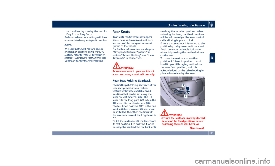
To tilt the seatback, lift the lever from
its rest position 0 to position 1 while
pushing the seatback to the back until reaching the required position. When
releasing the lever, the fixed positions
will be acknowledged by lever control
cable clicking in place to lock.
Ensure that seatback is fastened to the
position by trying to move it back and
forth. Lever control cable locks also
when fully folding the seatback down
on the seat.
To move the seatback in another
position, lift lever in position 1 and
hold it up until bringing seatback to
the new fixed position, which is
acknowledged by the cable locking in
place when releasing the lever.
WARNING!
• Ensure the seatback is always locked
in one of the fixed positions before
fastening the rear seat belts. An
(Continued)Understanding the Vehicle
3
103
Page 112 of 436
• Tilt the seat back to the upright
position (see “CArgo Area” in this
section).
• Reposition the head restraint to the
appropriate height for the passenger.
WARNING!
• A loose head restraint thrown
forward in a collision or hard stop
could cause serious injury or death
to occupants of the vehicle. Always
securely stow removed head
restraints in a location outside the
occupant compartment.
• ALL the head restraints MUST be
reinstalled in the vehicle to properly
protect the occupants. Follow the
re-installation instructions above
prior to operating the vehicle or
occupying a seat. Steering Wheel
Adjustment This feature allows you to tilt the
steering column upward or downward
or to lengthen or shorten it in order to
adjust the steering wheel to an
optimized position.
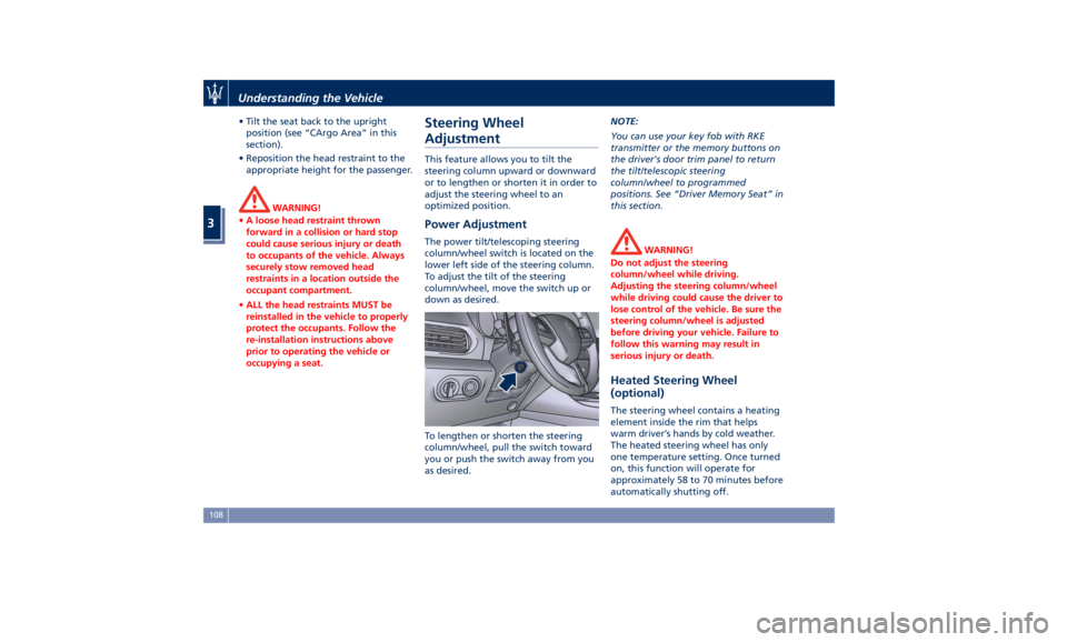
Power Adjustment The power tilt/telescoping steering
column/wheel switch is located on the
lower left side of the steering column.
To adjust the tilt of the steering
column/wheel, move the switch up or
down as desired.
To lengthen or shorten the steering
column/wheel, pull the switch toward
you or push the switch away from you
as desired. NOTE:
You can use your key fob with RKE
transmitter or the memory buttons on
the driver's door trim panel to return
the tilt/telescopic steering
column/wheel to programmed
positions. See “Driver Memory Seat” in
this section.
WARNING!
Do not adjust the steering
column/wheel while driving.
Adjusting the steering column/wheel
while driving could cause the driver to
lose control of the vehicle. Be sure the
steering column/wheel is adjusted
before driving your vehicle. Failure to
follow this warning may result in
serious injury or death.
Heated Steering Wheel
(optional) The steering wheel contains a heating
element inside the rim that helps
warm driver’s hands by cold weather.
The heated steering wheel has only
one temperature setting. Once turned
on, this function will operate for
approximately 58 to 70 minutes before
automatically shutting off.Understanding the Vehicle
3
108
Page 114 of 436
Adjustable Pedals (if
equipped) The adjustable pedals system is
designed to allow greater range of
pedals positions enabling driver
comfort with regard to the steering
wheel tilt and the seat position.
This feature allows the brake and
accelerator pedals to move toward or
away from the driver’s feet.
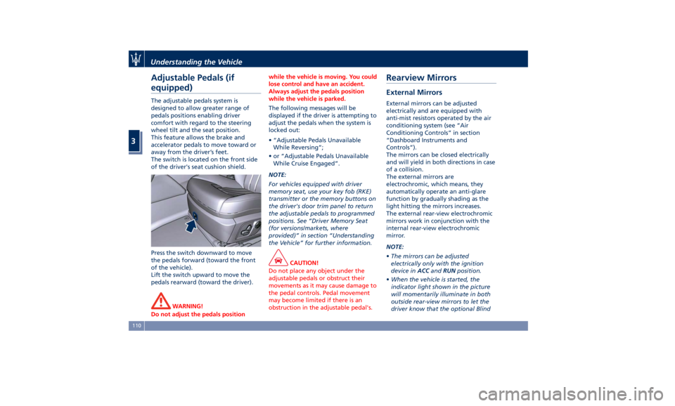
The switch is located on the front side
of the driver's seat cushion shield.
Press the switch downward to move
the pedals forward (toward the front
of the vehicle).
Lift the switch upward to move the
pedals rearward (toward the driver).
WARNING!
Do not adjust the pedals position while the vehicle is moving. You could
lose control and have an accident.
Always adjust the pedals position
while the vehicle is parked.
The following messages will be
displayed
if the driver is attempting to
adjust the pedals when the system is
locked out:
• “Adjustable Pedals Unavailable
While Reversing”;
• or “Adjustable Pedals Unavailable
While Cruise Engaged”.
NOTE:
For vehicles equipped with driver
memory seat, use your key fob (RKE)
transmitter or the memory buttons on
the driver's door trim panel to return
the adjustable pedals to programmed
positions. See “Driver Memory Seat
(for versions/markets, where
provided)” in section “Understanding
the Vehicle” for further information.
CAUTION!
Do not place any object under the
adjustable pedals or obstruct their
movements as it may cause damage to
the pedal controls. Pedal movement
may become limited if there is an
obstruction in the adjustable pedal's.Rearview Mirrors External Mirrors External mirrors can be adjusted
electrically and are equipped with
anti-mist resistors operated by the air
conditioning system (see “Air
Conditioning Controls” in section
“Dashboard Instruments and
Controls”).
The mirrors can be closed electrically
and will yield in both directions in case
of a collision.
The external mirrors are
electrochromic, which means, they
automatically operate an anti-glare
function by gradually shading as the
light hitting the mirrors increases.
The external rear-view electrochromic
mirrors work in conjunction with the
internal rear-view electrochromic
mirror.
NOTE:
• The mirrors can be adjusted
electrically only with the ignition
device in ACC and RUN position.
• When the vehicle is started, the
indicator light shown in the picture
will momentarily illuminate in both
outside rear-view mirrors to let the
driver know that the optional BlindUnderstanding the Vehicle
3
110
Page 121 of 436

Bi-Xenon Headlight (for
headlights without AFS) The gas-discharge (xenon) headlights
operate with an electric arc saturated
with Xenon gas under pressure,
instead of the incandescent filament.
The light produced is assuredly higher
compared to traditional light bulbs, in
terms of quality (brighter light) as well
as of the span and positioning of the
illuminated area.
WARNING!
If xenon headlamp replacement is
necessary, contact the Authorized
Maserati Dealer only: DANGER - RISK
OF ELECTRICAL SHOCK.
Headlight with AFS (for
versions/markets, where
provided) These headlights combines the “xeno”
technology to the AFS (Advanced
Frontlighting System) adaptive
features.
The system is able to process signals of
onboard systems and subsequently
start up five strategic steps in the
following situations:
• “motorway beam”; • “country beam”;
• “town beam”;
• “adverse weather beam”;
• “tourist beam” (for example in
countries with circulation on the
opposite side). In this case this
function must be activated via the
menu of MTC+ (refer to “MTC+
Settings” in section “Dashboard
Instruments and Controls”).
The advantages offered by the AFS
system are perceived especially in case
of bad weather, fog and/or insufficient
road indications providing broader
illumination of the side zones, which
are normally left in the dark, and for
motorway driving (see comparison
rendered below).
This surely increases driving safety as it
offers less eye stress and increased
orientation for the driver and better
detection of other persons on the
road sides (pedestrians, bicycle riders
and motorcycle drivers).
The table shows the light values (lux)
and the light flux (lumen) of AFS
headlights. Combining a bending mode and a
vertical adjustment, the system assures
better visibility of the road surface
when driving on a curve, steering, or
in the event of road deviations,
optimizing vertical and horizontal
light distribution according to the
current drive path.
The increased lateral illumination is
gained through a fixed bending light
or a cornering light (depending on the
market) elaborating information
about the steering angle, the vehicle
speed and the turn indicator.
The improved vertical illumination, in
case of fast acceleration and/or fast
deceleration, will assure the deeper
illuminated distance from the vehicle,
through a dynamical adaptation of
headlight vertical attitude.Understanding the Vehicle
3
117