2019 Hyundai Tucson lock
[x] Cancel search: lockPage 622 of 685
7-73
7
Maintenance
Headlamp and front fog lamp
aiming
Headlamp aiming
1. Inflate the tyres to the specifiedpressure and remove any loads
from the vehicle except the driver,
spare tyre, and tools.
2. The vehicle should be placed on a flat floor.
3. Draw vertical lines (Vertical lines passing through respective head
lamp centres) and a horizontal line
(Horizontal line passing through
centre of head lamps) on the
screen. 4. With the headlamp and battery in
normal condition, aim the head-
lamps so the brightest portion falls
on the horizontal and vertical
lines.
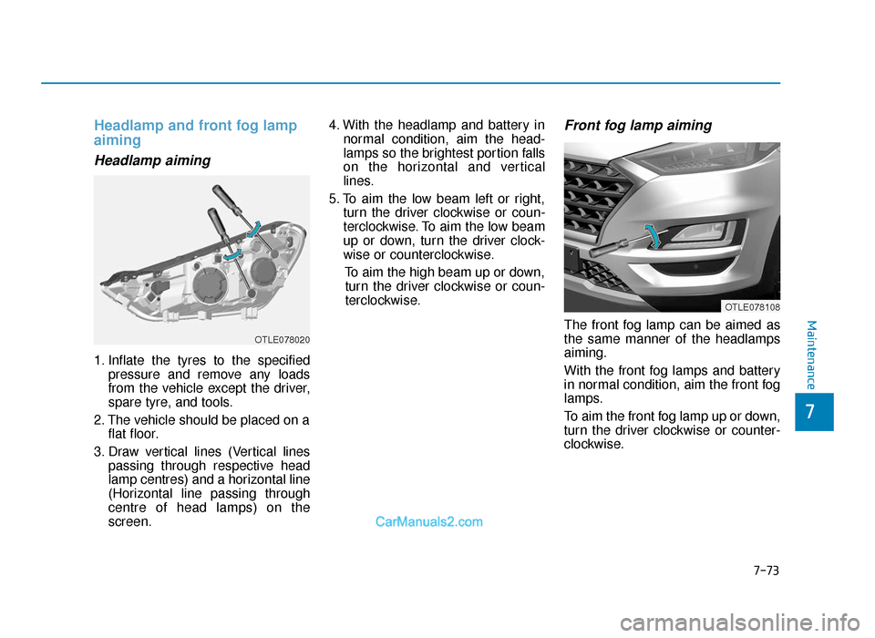
5. To aim the low beam left or right, turn the driver clockwise or coun-
terclockwise. To aim the low beam
up or down, turn the driver clock-
wise or counterclockwise.
To aim the high beam up or down,turn the driver clockwise or coun-
terclockwise.
Front fog lamp aiming
The front fog lamp can be aimed as
the same manner of the headlamps
aiming.
With the front fog lamps and battery
in normal condition, aim the front fog
lamps.
To aim the front fog lamp up or down,
turn the driver clockwise or counter-
clockwise.
OTLE078020
OTLE078108
TLe UK 7.qxp 5/10/2018 1:39 PM Page 73
Page 627 of 685
![Hyundai Tucson 2019 Owners Manual - RHD (UK, Australia) 7-78
Maintenance
[A] : Stop/tail lamp , [B] : Turn signal lamp
5. Remove the socket from theassembly by turning the socket
counterclockwise until the tabs on
the socket align with the slots on
the ass](/manual-img/35/19695/w960_19695-626.png "Hyundai Tucson 2019 Owners Manual - RHD (UK, Australia) 7-78
Maintenance
[A] : Stop/tail lamp , [B] : Turn signal lamp
5. Remove the socket from theassembly by turning the socket
counterclockwise until the tabs on
the socket align with the slots on
the ass")
7-78
Maintenance
[A] : Stop/tail lamp , [B] : Turn signal lamp
5. Remove the socket from theassembly by turning the socket
counterclockwise until the tabs on
the socket align with the slots on
the assembly.
6. Remove the bulb from the socket by pressing it in and rotating it
counterclockwise until the tabs on
the bulb align with the slots in the
socket. Pull the bulb out of the
socket.
7. Insert a new bulb by inserting it into the socket and rotating it until it
locks into place. 8. Install the socket in the assembly
by aligning the tabs on the socket
with the slots in the assembly.
Push the socket into the assembly
and turn the socket clockwise.
9. Reinstall the lamp assembly to the body of the vehicle.
Stop/tail lamp, tail lamp
(Type B, LED)
If the LED lamp does not operate, we
recommend you to have the vehicle
checked by a HYUNDAI authorised
repairer.
OTLE078037
TLe UK 7.qxp 5/10/2018 1:39 PM Page 78
Page 628 of 685
7-79
7
Maintenance
Inside lamp
Tail lamp/Back-up lamp
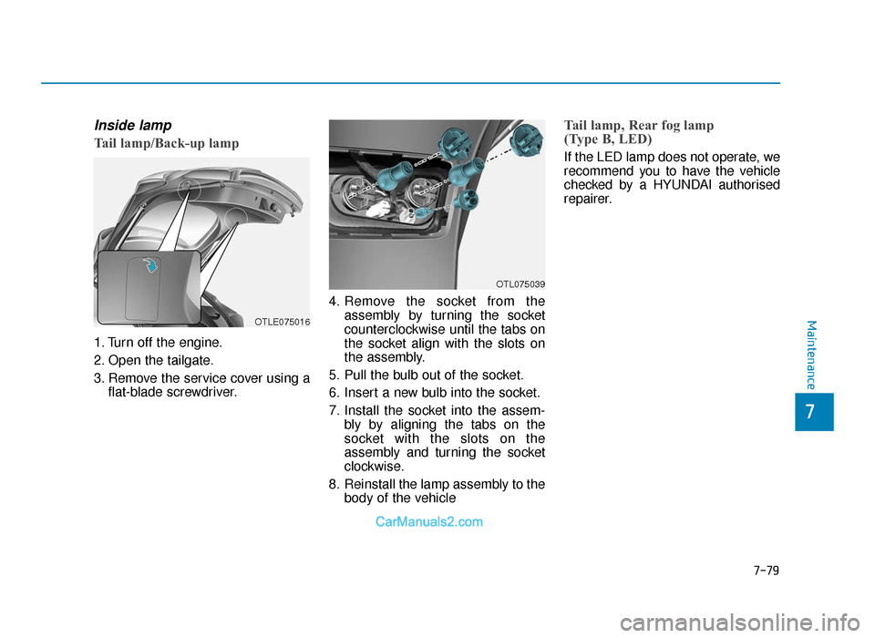
1. Turn off the engine.
2. Open the tailgate.
3. Remove the service cover using aflat-blade screwdriver. 4. Remove the socket from the
assembly by turning the socket
counterclockwise until the tabs on
the socket align with the slots on
the assembly.
5. Pull the bulb out of the socket.
6. Insert a new bulb into the socket.
7. Install the socket into the assem- bly by aligning the tabs on the
socket with the slots on the
assembly and turning the socket
clockwise.
8. Reinstall the lamp assembly to the body of the vehicle
Tail lamp, Rear fog lamp
(Type B, LED)
If the LED lamp does not operate, we
recommend you to have the vehicle
checked by a HYUNDAI authorised
repairer.
OTLE075016
OTL075039
TLe UK 7.qxp 5/10/2018 1:39 PM Page 79
Page 629 of 685
7-80
Maintenance
Rear fog lamp (if equipped)
1. Remove the socket from theassembly by turning the socket
counterclockwise until the tabs on
the socket align with the slots on
the assembly.
2. Remove the bulb from the socket by pressing it in and rotating it
counterclockwise until the tabs on
the bulb align with the slots in the
socket. Pull the bulb out of the
socket.
3. Insert a new bulb in the socket.
4. Reinstall the light assembly to the body of the vehicle.
High mounted stop lamp
replacement
If the high mounted stop lamp does not
operate, we recommend that you con-
tact a HYUNDAI authorised repairer.
License plate light bulb
replacement
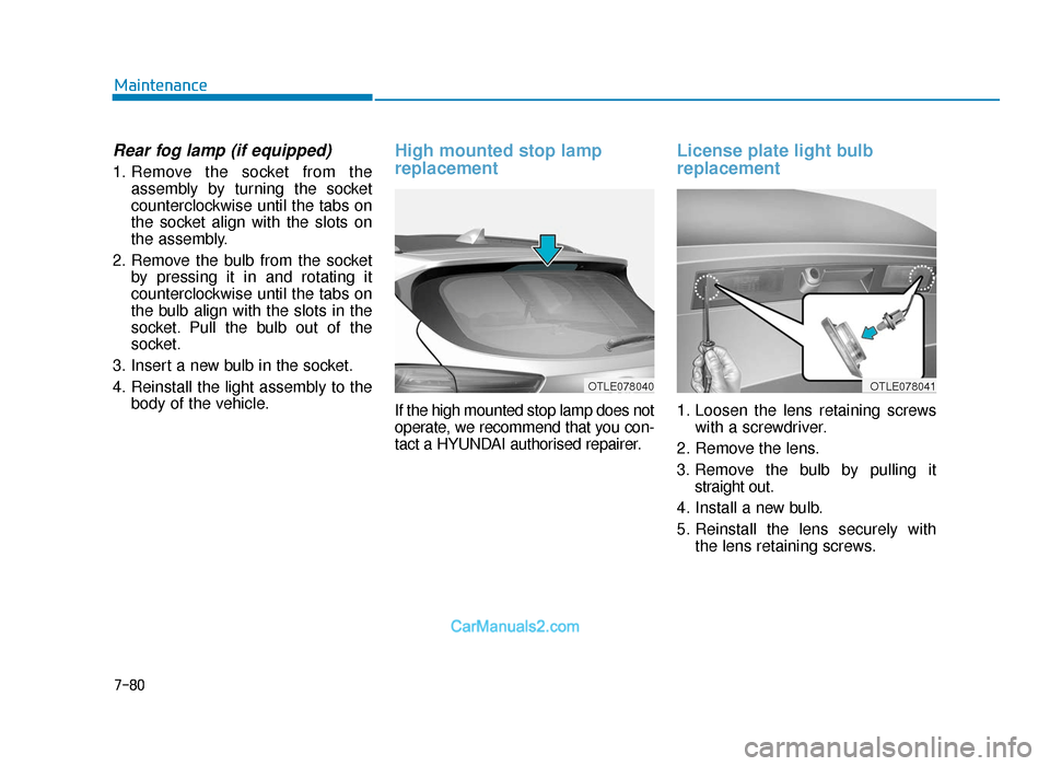
1. Loosen the lens retaining screwswith a screwdriver.
2. Remove the lens.
3. Remove the bulb by pulling it straight out.
4. Install a new bulb.
5. Reinstall the lens securely with the lens retaining screws.
OTLE078040OTLE078041
TLe UK 7.qxp 5/10/2018 1:39 PM Page 80
Page 651 of 685
Adding the urea solution
To refill the urea solution fromthe refill hose
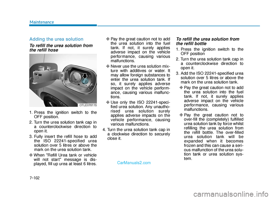
1. Press the ignition switch to the
OFF position.
2. Turn the urea solution tank cap in a counterclockwise direction to
open it.
3. Fully insert the refill hose to add the ISO 22241-specified urea
solution over 5 litres or above the
mark on the urea solution tank.
❈ When "Refill Urea tank or vehicle
will not start" message is dis-
played, fill up urea at least 6 litres. ❈
Pay the great caution not to add
the urea solution into the fuel
tank. If not, it surely applies
adverse impact on the vehicle
performance, causing various
malfunctions.
❈ Never use the urea solution mix-
ture with additives or water. It
may allow foreign substances to
enter the urea solution tank. If
so, it surely applies adverse
impact on the vehicle perform-
ance, causing various malfunc-
tions.
❈ Use only the ISO 22241-speci-
fied urea solution. Any unautho-
rised urea solution surely
applies adverse impacts on the
vehicle performance, causing
various malfunctions.
4. Turn the urea solution tank cap in a clockwise direction to securely
close it.
To refill the urea solution fromthe refill bottle
1. Press the ignition switch to the
OFF position
2. Turn the urea solution tank cap in a counterclockwise direction to
open it.
3. Add the ISO 22241-specified urea solution over 5 litres or above the
mark on the urea solution tank.
❈ Pay the great caution not to add
the urea solution into the fuel
tank. If not, it surely applies
adverse impact on the vehicle
performance, causing various
malfunctions.
❈ Pay the great caution not to
over-fill the (completely) fulfilled
urea solution tank by force whilst
refilling the urea solution from
the refill bottle. The over-filled
urea solution tank will be
expanded when it becomes
frozen and this can cause a seri-
ous malfunction of the urea solu-
tion tank or urea solution sys-
tem.
7-102
Maintenance
OTLE078115
TLe UK 7.qxp 6/12/2018 2:51 PM Page 102
Page 652 of 685
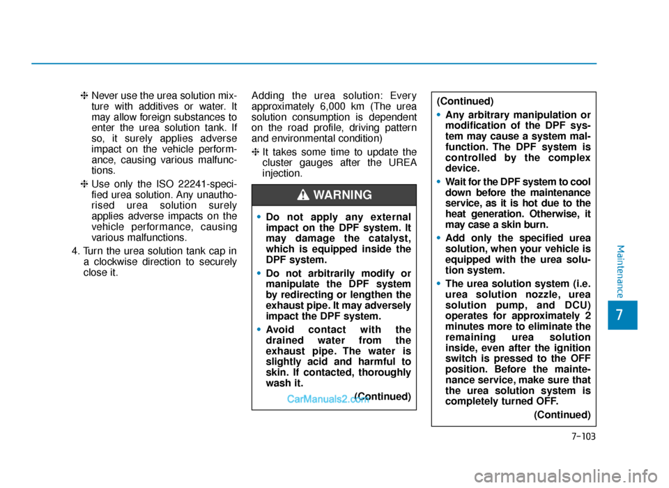
❈Never use the urea solution mix-
ture with additives or water. It
may allow foreign substances to
enter the urea solution tank. If
so, it surely applies adverse
impact on the vehicle perform-
ance, causing various malfunc-
tions.
❈ Use only the ISO 22241-speci-
fied urea solution. Any unautho-
rised urea solution surely
applies adverse impacts on the
vehicle performance, causing
various malfunctions.
4. Turn the urea solution tank cap in a clockwise direction to securely
close it. Adding the urea solution: Every
approximately 6,000 km (The urea
solution consumption is dependent
on the road profile, driving pattern
and environmental condition)
❈
It takes some time to update the
cluster gauges after the UREA
injection.
7-103
7
Maintenance
•Do not apply any external
impact on the DPF system. It
may damage the catalyst,
which is equipped inside the
DPF system.
• Do not arbitrarily modify or
manipulate the DPF system
by redirecting or lengthen the
exhaust pipe. It may adversely
impact the DPF system.
• Avoid contact with the
drained water from the
exhaust pipe. The water is
slightly acid and harmful to
skin. If contacted, thoroughly
wash it.
(Continued)
WARNING
(Continued)
•Any arbitrary manipulation or
modification of the DPF sys-
tem may cause a system mal-
function. The DPF system is
controlled by the complex
device.
• Wait for the DPF system to cool
down before the maintenance
service, as it is hot due to the
heat generation. Otherwise, it
may case a skin burn.
• Add only the specified urea
solution, when your vehicle is
equipped with the urea solu-
tion system.
• The urea solution system (i.e.
urea solution nozzle, urea
solution pump, and DCU)
operates for approximately 2
minutes more to eliminate the
remaining urea solution
inside, even after the ignition
switch is pressed to the OFF
position. Before the mainte-
nance service, make sure that
the urea solution system is
completely turned OFF.
(Continued)
TLe UK 7.qxp 6/12/2018 2:51 PM Page 103
Page 671 of 685
8-15
8
Specifications & Consumer information
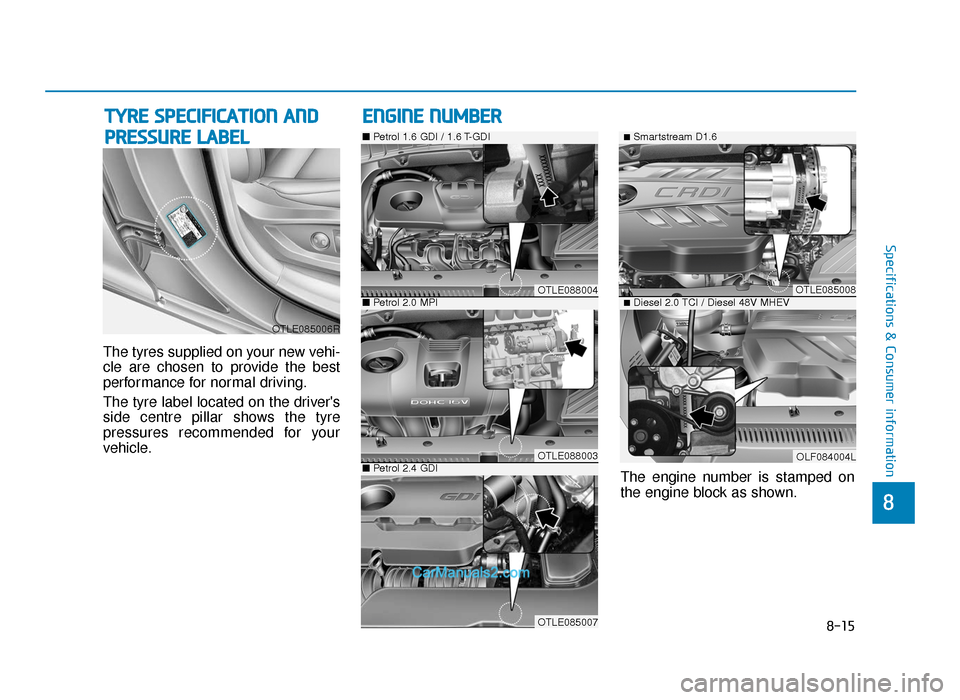
The tyres supplied on your new vehi-
cle are chosen to provide the best
performance for normal driving.
The tyre label located on the driver's
side centre pillar shows the tyre
pressures recommended for your
vehicle.
TYRE SPECIFICATION AND
PRESSURE LABEL
ENGINE NUMBER
The engine number is stamped on
the engine block as shown.
OTLE085006R
OTLE088004
■ Petrol 1.6 GDI / 1.6 T-GDI
OTLE088003
■Petrol 2.0 MPI
OTLE085007
■ Petrol 2.4 GDI
OTLE085008
■Smartstream D1.6
OLF084004L
■Diesel 2.0 TCI / Diesel 48V MHEV
TLe UK 8.qxp 6/12/2018 3:18 PM Page 15
Page 675 of 685
I-2
Accessing your vehicle ...................................................3-4Immobiliser system....................................................3-13
Remote key ..................................................................3-4
Smart key .....................................................................3-8\
Active bonnet lift system..............................................2-70 Non-activation situations ...........................................2-71
Possible activation situations .....................................2-70
System malfunction ...................................................2-72
Adding the urea solution ............................................7-102
Air bag - supplemental restraint system .......................2-50 Additional safety precautions ....................................2-69
Air bag warning labels...............................................2-69
Do not install a Child Restraint System on the front passenger seat unless the air bag is deactivated ......2-62
How does the air bags system operate?.....................2-57
SRS care.....................................................................2-6\
8
What to expect after an air bag inflates.....................2-61
Where are the air bags? .............................................2-52
Why didn't my air bag go off in a collision?.............2-63
Air cleaner ....................................................................7-27\
Air conditioner compressor label .................................8-16
Antenna ........................................................................\
...4-3 Anti-lock Brake System (ABS) ....................................5-56
Appearance care ...........................................................7-83
Exterior care...............................................................7-83
Interior care................................................................7-89
Ashtray........................................................................\
3-171
Audio (without touch screen) .......................................4-15 Getting to know the basic operations ........................4-21
System layout - control panel ....................................4-15
System layout - steering wheel remote control .........4-17
Turning the display on or off .....................................4-20
Turning the system on or off .....................................4-20
Audio / Video / Navigation system (AVN) ....................4-5
Audio system specifications .........................................4-46 Bluetooth....................................................................4-47\
USB........................................................................\
....4-46
Auto hold ......................................................................5-\
52
Automatic climate control system ..............................3-150 Automatic heating and air conditioning ..................3-151
Manual heating and air conditioning .......................3-152
System maintenance ................................................3-160
System operation .....................................................3-158
Automatic transaxle ......................................................5-24
AUX, USB and iPod
®port .............................................4-2
Index
A
TLe UK Index.qxp 6/12/2018 3:27 PM Page 2