Page 114 of 685
3-22
Convenient features of your vehicle
STEERING WHEEL
Electric power steering (EPS)
The system assists you with steering
the vehicle. If the engine is off or if
the power steering system becomes
inoperative, the vehicle may still be
steered, but it will require increased
steering effort.
Also, the steering effort becomes
heavier as the vehicle’s speed
increases and becomes lighter as
the vehicle’s speed decreases for
better control of the steering wheel.
Should you notice any change in the
effort required to steer during normal
vehicle operation, we recommend
that the system be checked by a
HYUNDAI authorised repairer.If the Electric Power Steering System
does not operate normally, the warn-
ing light ( ) will illuminate on the
instrument cluster. The steering
wheel may become difficult to con-
trol or operate. We recommend to
take your vehicle to a HYUNDAI
authorised repairer and have the sys-
tem checked as soon as possible.
Information
The following symptoms may occur
during normal vehicle operation:
• The steering effort may be highimmediately after placing the igni-
tion switch in the ON position.
This happens as the system per-
forms the EPS system diagnostics.
When the diagnostics is completed,
the steering wheel will return to its
normal condition.
(Continued)(Continued)
• A click noise may be heard from the
EPS relay after the ignition switch is
placed to the ON or LOCK/OFF
position.
A click noise may be heard from the
EPS relay after the Engine Start/Stop
button is in the ON or OFF position.
(With Smart key system)
• Motor noise may be heard when the vehicle is at a stop or at a low driv-
ing speed.
• When you operate the steering wheel in low temperature, the steer-
ing effort may be high and abnor-
mal noise may occur. If temperature
rises, the noise will disappear. This
is a normal condition.
• When the vehicle is stationary, if you turn the steering wheel all the
way to the left or right continuously,
the steering wheel effort increases.
This is not a system malfunction. As
time passes, the steering wheel
effort will return to its normal con-
dition.
i
NOTICE
TLe UK 3a(~109).qxp 6/12/2018 2:21 PM Page 22
Page 551 of 685
7
Fuses ......................................................................7-\
49
Fuse/Relay panel description ......................................7-54
Light bulbs.............................................................7-68
Headlamp, low beam assist - static, position lamp,
turn signal lamp and fog lamp light bulb
replacement ......................................................................7-\
69
Front fog lamp .................................................................7-71
Side repeater lamp replacement .................................7-72
Headlamp and front fog lamp aiming ........................7-73
Rear combination light bulb replacement .................7-77
High mounted stop lamp replacement .......................7-80
License plate light bulb replacement .........................7-80
Interior light bulb replacement ....................................7-81
Appearance care ..................................................7-83
Exterior care ....................................................................7-83\
Interior care......................................................................7-\
89
Emission control system .....................................7-92
Crankcase emission control system ...........................7-92
Evaporative emission control system.........................7-92
Exhaust emission control system ...............................7-93
Selective catalytic reduction ........................................7-98
Urea gauge .......................................................................7\
-98
Low urea warning message..........................................7-99
Malfunction with the SCR system ............................7-100
Clearing the vehicle-restarting restriction.............7-101
Adding the urea solution.............................................7-102
Storing the urea solution ............................................7-105
Urea solution purity .....................................................7-105
TLe UK 7.qxp 5/10/2018 1:31 PM Page 2
Page 599 of 685
7-50
MaintenanceDo not use a screwdriver or any
other metal object to remove fuses
because it may cause a short cir-
cuit and damage the system. • When replacing a blown fuse or
relay with a new one, make sure
the new fuse or relay fits tightly
into the clips. The incomplete
fastening fuse or relay may
cause the vehicle wiring and
electric systems damage and a
possible fire.
• Do not remove fuses, relays and terminals fastened with bolts or
nuts. The fuses, relays and ter-
minals may be fastened incom-
pletely, and it may cause a pos-
sible fire. If fuses, relays and ter-
minals fastened with bolts or
nuts are blown, we recommend
that you consult a HYUNDAI
authorised repairer.
• Do not input any other objects except fuses or relays into
fuse/relay terminals such as a
driver or wiring. It may cause
contact failure and system mal-
function.
NOTICENOTICE
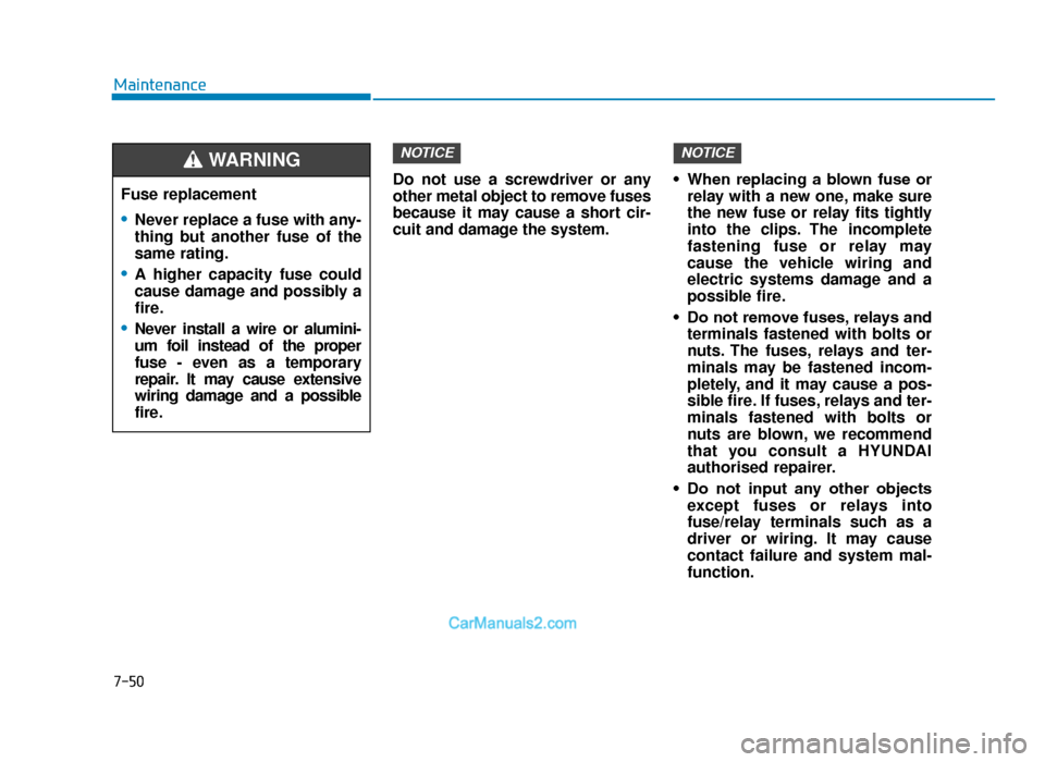
Fuse replacement
•Never replace a fuse with any-
thing but another fuse of the
same rating.
•A higher capacity fuse could
cause damage and possibly a
fire.
•Never install a wire or alumini-
um foil instead of the proper
fuse - even as a temporary
repair. It may cause extensive
wiring damage and a possible
fire.
WARNING
TLe UK 7.qxp 5/10/2018 1:35 PM Page 50
Page 603 of 685
7-54
Maintenance
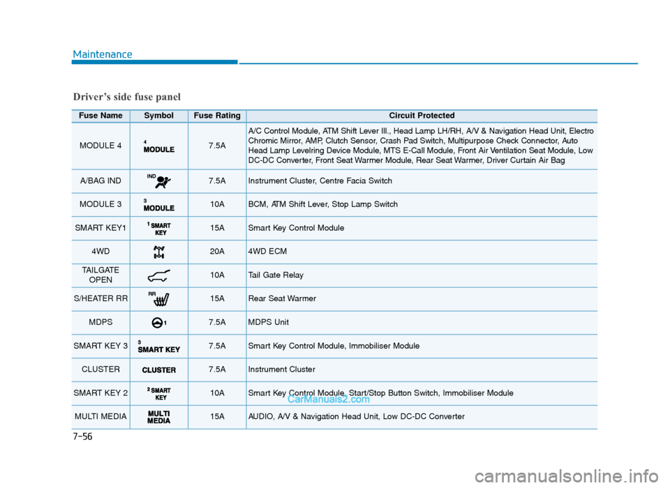
Fuse/Relay panel description
Driver’s side fuse panel
Inside the fuse/relay box covers, you
can find the fuse/relay label describ-
ing fuse/relay name and capacity.
Information
Not all fuse panel descriptions in this
manual may be applicable to your
vehicle. It is accurate at the time of
printing. When you inspect the fuse
box on your vehicle, refer to the fuse
box label.
i
OTLE078067R
OTLE078031
TLe UK 7.qxp 5/10/2018 1:35 PM Page 54
Page 604 of 685
7-55
7
Maintenance
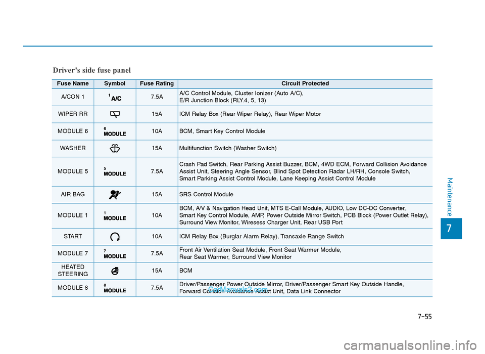
Driver’s side fuse panel
Fuse Name SymbolFuse RatingCircuit Protected
A/CON 1 7.5A A/C Control Module, Cluster Ionizer (Auto A/C),
E/R Junction Block (RLY.4, 5, 13)
WIPER RR15A ICM Relay Box (Rear Wiper Relay), Rear Wiper Motor
MODULE 6 10A BCM, Smart Key Control Module
WASHER 15A Multifunction Switch (Washer Switch)
MODULE 5 7.5A Crash Pad Switch, Rear Parking Assist Buzzer, BCM, 4WD ECM, Forward Collision Avoidance
Assist Unit, Steering Angle Sensor, Blind Spot Detection Radar LH/RH, Console Switch,
Smart Parking Assist Control Module, Lane Keeping Assist Control Module
AIR BAG15A SRS Control Module
MODULE 1 10A BCM, A/V & Navigation Head Unit, MTS E-Call Module, AUDIO, Low DC-DC Converter,
Smart Key Control Module, AMP, Power Outside Mirror Switch, PCB Block (Power Outlet Relay),
Surround View Monitor, Wiresess Charger Unit, Rear USB Port
START 10A ICM Relay Box (Burglar Alarm Relay), Transaxle Range Switch
MODULE 7 7.5A Front Air Ventilation Seat Module, Front Seat Warmer Module,
Rear Seat Warmer, Surround View Monitor
HEATED
STEERING15A BCM
MODULE 8 7.5A Driver/Passenger Power Outside Mirror, Driver/Passenger Smart Key Outside Handle,
Forward Collision Avoidance Assist Unit, Data Link Connector
TLe UK 7.qxp 5/10/2018 1:36 PM Page 55
Page 605 of 685
7-56
Maintenance
Fuse Name SymbolFuse RatingCircuit Protected
MODULE 4 7.5A
A/C Control Module, ATM Shift Lever Ill., Head Lamp LH/RH, A/V & Navigation Head Unit, Electro
Chromic Mirror, AMP, Clutch Sensor, Crash Pad Switch, Multipurpose Check Connector, Auto
Head Lamp Levelring Device Module, MTS E-Call Module, Front Air Ventilation Seat Module, Low
DC-DC Converter, Front Seat Warmer Module, Rear Seat Warmer, Driver Curtain Air Bag
A/BAG IND 7.5A Instrument Cluster, Centre Facia Switch
MODULE 3 10A BCM, ATM Shift Lever, Stop Lamp Switch
SMART KEY115A Smart Key Control Module
4WD 20A 4WD ECM
TAILGATEOPEN10A Tail Gate Relay
S/HEATER RR15A Rear Seat Warmer
MDPS 7.5A MDPS Unit
SMART KEY 3 7.5A Smart Key Control Module, Immobiliser Module
CLUSTER 7.5A Instrument Cluster
SMART KEY 2 10A Smart Key Control Module, Start/Stop Button Switch, Immobiliser Module
MULTI MEDIA 15A AUDIO, A/V & Navigation Head Unit, Low DC-DC Converter
Driver’s side fuse panel
TLe UK 7.qxp 5/10/2018 1:36 PM Page 56
Page 606 of 685
7-57
7
Maintenance
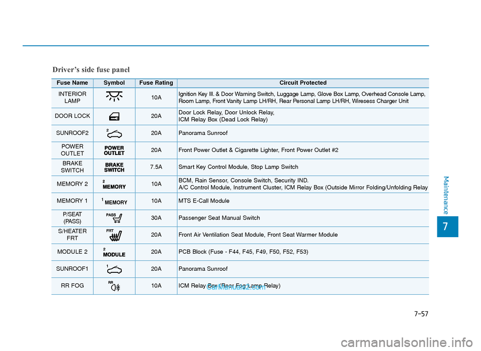
Driver’s side fuse panel
Fuse Name SymbolFuse RatingCircuit Protected
INTERIORLAMP10A Ignition Key Ill. & Door Warning Switch, Luggage Lamp, Glove Box Lamp, Overhead Console Lamp,
Room Lamp, Front Vanity Lamp LH/RH, Rear Personal Lamp LH/RH, Wiresess Charger Unit
DOOR LOCK 20A Door Lock Relay, Door Unlock Relay,
ICM Relay Box (Dead Lock Relay)
SUNROOF220A Panorama Sunroof
POWER
OUTLET 20A Front Power Outlet & Cigarette Lighter, Front Power Outlet #2
BRAKE
SWITCH 7.5A Smart Key Control Module, Stop Lamp Switch
MEMORY 2 10A BCM, Rain Sensor, Console Switch, Security IND.
A/C Control Module, Instrument Cluster, ICM Relay Box (Outside Mirror Folding/Unfolding Relay
MEMORY 1MEMORY110A MTS E-Call Module
P/SEAT (PASS)30A Passenger Seat Manual Switch
S/HEATER FRT 20A Front Air Ventilation Seat Module, Front Seat Warmer Module
MODULE 2 20A PCB Block (Fuse - F44, F45, F49, F50, F52, F53)
SUNROOF120A Panorama Sunroof
RR FOG10A ICM Relay Box (Rear Fog Lamp Relay)
TLe UK 7.qxp 5/10/2018 1:36 PM Page 57
Page 608 of 685
7-59
7
Maintenance
Engine compartment fuse panel
Inside the fuse/relay box covers, you
can find the fuse/relay label describ-
ing fuse/relay name and capacity.
Information
Not all fuse panel descriptions in this
manual may be applicable to your
vehicle. It is accurate at the time of
printing. When you inspect the fuse
box on your vehicle, refer to the fuse
box label.
i
OTLE078029
OTLE078030
TLe UK 7.qxp 5/10/2018 1:36 PM Page 59