Page 201 of 320

199
The speed limit sticker must be secured
to the interior of the vehicle in the driver's
field of vision, to remind you that a wheel
is in temporary use.Take care, the sealant product is harmful
if swallowed and causes irritation to the
eyes.
Keep this product out of the reach of
children.
The use-by date of the fluid is marked on
the bottle.
After use, do not discard the bottle in
standard waste, take it to a CITROËN
dealer or an authorised waste disposal
site.
Do not forget to obtain a new bottle of
sealant, available from a CITROËN dealer
or a qualified workshop.
Checking/adjusting tyre
pressures
You can also use the compressor,
without injecting sealant, to check and, if
necessary, adjust the tyre pressures.
F
R
emove the valve cap from the tyre and
place it in a clean area.
F
U
ncoil the pipe stowed under the
compressor.
The tyre inflation pressures are given on
this label.
F
S
witch on the ignition.
F
S
tart the compressor by turning the switch
to the " l" position until the pressure of the
tyre reaches 2.0
bars. The sealant product
is injected under pressure into the tyre;
do not disconnect the pipe from the valve
during this operation (risk of blowback). If a pressure of 2
bars is not reached
after about 7
minutes, this indicates
that the tyre is not repairable; contact a
CITROËN dealer or a qualified workshop
for assistance.
F
P
lace the switch in the "
O" position.
F
D
isconnect the compressor's electric plug
from the vehicle's 12
V socket.
F
R
eplace the cap on the valve.
F
R
emove the kit.
F
R
emove and then store the bottle of sealant.
Do not exceed the speed of 50 mph
(80
k
m/h) when driving with a tyre repaired
using this type of kit.
F
D
rive immediately for approximately three
miles (five kilometres), at reduced speed
(between 12 and 37 mph (20 and 60 km/h)),
to plug the puncture.
F
S
top to check the repair and measure the
tyre pressure using the kit.
8
In the event of a breakdown
Page 202 of 320

200
F Check that the compressor switch is at the "O " position.
F
U
ncoil fully the electric cable, stowed under
the compressor.
Only the 12
V socket located at the front
of the vehicle can be used to power the
compressor.
F
S
crew the pipe onto the valve and tighten
f i r m l y.
F
C
onnect the compressor's electric plug to
the vehicle's 12
V socket.
F
S
witch on the ignition.
The tyre inflation pressures are given on
this label. F
S
tart the compressor by placing the switch
at position " I" and adjust the pressure to the
value shown on the vehicle's tyre pressure
label. To deflate: press the black button
located on the compressor pipe, near the
valve connection.
If a pressure of 2
bars is not reached after
7
minutes, this indicates that the tyre is
not repairable; contact a CITROËN dealer
or a qualified workshop for assistance.
F
O
nce the correct pressure is reached, put
the switch to the " O" position.
F
R
emove the kit then stow it.Do not drive more than 125
miles (200 km)
with the repaired tyre; see a CITROËN
dealer or a qualified workshop to change
the tyre.
Should the pressure of one or more tyres
be adjusted, it is necessary to reinitialise
the under-inflation detection system.
For more information on Under-inflation
detection , refer to the corresponding
section.
Spare wheel
Scan the QR code on page 3 to view
explanatory videos.
Procedure for changing a damaged wheel with
the spare wheel using the tools provided with
the vehicle.
For more information on the Tool kit , refer
to the corresponding section.
F Park the vehicle without obstructing any traffic and apply the parking brake.
F
F
ollow the safety instructions (hazard warning
lamps, warning triangle, wearing high visibility
vest, etc.) according to the legislation in force
in the country where you are driving.
F
S
witch off the ignition.
In the event of a breakdown
Page 203 of 320

201
Access to the spare wheel
F Access to the spare wheel is from the rear.
F
I
f your vehicle is fitted with a towing device,
raise the rear of the vehicle using the
jack (must be at jacking point B ) to allow
sufficient space to remove the spare wheel.
Remove the spare wheel from the
carrier
F Depending on version, open the tailgate or the side-hinged doors.
F
A
ccess the carrier bolt, located on the rear
door sill. F
S
lacken the bolt using the wheelbrace until
the carrier is low enough to allow the carrier
hook to be disengaged.
F
R
elease the carrier from the hook, take the
spare wheel and place it next to the wheel
to be changed.
Refit the spare wheel in the
carrier
F Position the wheel facing the carrier.
F P rogressively return the wheel to the carrier
by pushing alternately from left to right until
it is clear of the hook fixing area.
F
E
ngage the carrier on the hook, then tighten
the bolt using the wheelbrace until the bolt
is completely tight.
8
In the event of a breakdown
Page 204 of 320

202
Removing a wheel
Parking the vehicle
Immobilise the vehicle where it does not
block traffic: the ground must be level,
stable and non-slippery.
With a manual gearbox, engage first gear
then switch off the ignition to block the
wheels.
With an automatic gearbox, place the gear
selector in position P then switch off the
ignition to block the wheels.
Apply the parking brake and check that
the indicator lamp is on in the instrument
panel.
The occupants must get out of the vehicle
and wait where they are safe.
Never go underneath a vehicle raised
using a jack; use an axle stand.
With an electric parking brake, place
a chock against the wheel diagonally
opposite to the one being replaced.Wheel with wheel trim
When removing the wheel, first remove
the wheel trim by pulling at the valve
aperture using the wheelbrace. Do not use:
-
t
he jack for any other purpose than
lifting the vehicle,
- a j ack other than the one supplied by
the manufacturer.
F
P
lace the foot of the jack on the ground and
ensure that it is directly below the A or B
jacking point provided on the underbody,
whichever is closest to the wheel to be
changed.
F
W
ith a steel wheel, remove the trim using
tool 8 .
F
W
ith an alloy wheel, remove the cap from
each of the bolts using tool 8 .
F
I
f your vehicle is so equipped, fit security
bolt socket 9 to wheelbrace 6 to slacken the
security bolt.
F
S
lacken (without removing) the other wheel
bolts using just wheelbrace 6 .
In the event of a breakdown
Page 205 of 320

203
F Extend jack 7 until its head comes into contact with jacking point A or B , whichever
is used; the contact sur face A or B of the
vehicle must be correctly engaged in the
central part of the head of the jack.
F
Ra
ise the vehicle until there is sufficient
space between the wheel and the ground
to admit the spare (not punctured) wheel
easily.
Ensure that the jack is stable. If the
ground is slippery or loose, the jack may
slip or drop – risk of injury!
Take care to place the jack only at the
jacking points A or B under the vehicle,
ensuring that the contact point of the
vehicle is centred on the jack head.
Other wise, there is a risk of damage to
the vehicle and/or the jack dropping – risk
of injury!
It is prohibited to lie down on the ground to
position yourself underneath the vehicle. F
R emove the bolts and store them in a clean
place.
F
R
emove the wheel.
Fitting a wheel
F Put the wheel in place on the hub.
F S crew in the bolts by hand as far as
possible.
F
P
re-tighten the security bolt using the
wheelbrace 6 fitted with security socket 9 .
F
P
re-tighten the other bolts using wheelbrace
6 o n l y. F
L
ower the vehicle again fully.
F
F
old jack 7 and detach it.
F
I
f your vehicle is so equipped, tighten the
security bolt using the wheelbrace 6 fitted
with security socket 9 .
F T ighten the other bolts using wheelbrace 6
o n l y.
F
S
tore the tools.
8
In the event of a breakdown
Page 206 of 320

204
Fitting a steel or "space-saver" spare
wheel
If your vehicle is fitted with alloy wheels,
when tightening the bolts on refitting it is
normal to notice that the washers do not
come into contact with the steel or "space-
saver" spare wheel. The wheel is secured
by the conical contact of each bolt.
After changing a wheel
Stow the punctured wheel in the carrier.
Go to a CITROËN dealer or a qualified
workshop as soon as possible.
Have the punctured tyre examined. After
inspection, the technician will advise you
on whether the tyre can be repaired or if it
must be replaced.
Some driving aid functions should be
disabled, e.g. the Active Safety Brake. If your vehicle has tyre under-inflation
detection, check the tyre pressures and
reinitialise the system.
For more information on Under-inflation
detection
, refer to the corresponding
section.
Wheel with trim
When refitting the wheel , refit the trim
starting by placing its notch facing the
valve and press around its edge with the
palm of your hand.
The tyre inflation pressures are given on
this label.
Changing a bulb
The lamps have polycarbonate lenses with
a protective coating:
F
d
o not clean them using a dr y or
abrasive cloth, nor with a detergent
or solvent product,
F
u
se a sponge and soapy water or a pH
neutral product,
F
w
hen using a high pressure washer
on persistent marks, do not keep the
lance directed towards the lamps or
their edges for too long, so as not to
damage their protective coating and
seals.
Changing a bulb should only be done after
the lamp has been switched off for several
minutes (risk of serious burns).
F
D
o not touch the bulb directly with your
fingers, use a lint-free cloth.
It is essential only to use anti-ultraviolet
(UV) type bulbs, so as not to damage the
lamp.
Always replace a failed bulb with a new
bulb of the same type and specification.
In the event of a breakdown
Page 207 of 320

205
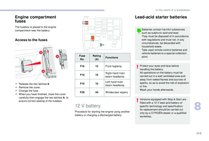
Light-emitting diodes (LED)
For the replacement of this type of bulb,
you must contact a CITROËN dealer or a
qualified workshop.
Halogen bulbs
To ensure good quality lighting, check
that the bulb is correctly positioned in its
housing.In some weather conditions (e.g. low
temperature or humidity), the presence
of misting on the internal sur face of the
glass of the headlamps and rear lamps is
normal; it disappears after the lamps have
been on for a few minutes.
Types of bulb
Various types of bulb are fitted to your vehicle.
To remove them:
Ty p e A
Ty p e B Ty p e C
Ty p e D
Halogen bulbs must be changed with the
lamp off for a few minutes (risk of severe
burns). Do not touch the bulb directly, use
a lint-free cloth.
When each operation has been
completed, check the operation of the
lighting.
All glass bulb: pull gently as it is fitted by
pressure.
Bayonet bulb: press on the bulb then turn it
anti-clockwise. Halogen bulb: release the retaining spring from
its housing.
Halogen bulb: turn the bulb anti-clockwise.
Opening the bonnet /Access to bulbs
With the engine warm, proceed with
caution – risk of burns!
Take care with objects or clothing that
could be caught in the blades of the
cooling fan – risk of strangulation!
After changing a bulb
When refitting, close the protective cover
very carefully to guarantee the sealing of
the lamp.
8
In the event of a breakdown
Page 208 of 320
206
Model A
Model BModel C
Direction indicator side repeater
Ty p e A, W Y5W-5W (amber)
-
P
ush the repeater towards the rear and
disengage it.
-
W
hen refitting, engage the repeater towards
the front and then bring it towards the rear.
Amber coloured bulbs (direction indicators and
side repeaters) must be replaced with bulbs of
identical specification and colour.
Front lamps
For more information on Changing a bulb
and, in particular, the types of bulb, refer to the
corresponding section.
1.Sidelamps/daytime running lamps.
Ty p e
A, W21/5W or LED (depending on
ve r s i o n)
2. Main beam headlamps.
Ty p e
C, H1
3. Dipped beam headlamps.
Ty p e
C, H7
4. Direction indicator.
Ty p e
B, PY21W
5. Foglamp.
Ty p e
D, H11
In the event of a breakdown