2018 SUBARU CROSSTREK warning
[x] Cancel search: warningPage 130 of 474
(133,1)
北米Model "A1320BE-C" EDITED: 2017/ 10/ 10
Rear gate
WARNING
.To prevent dangerous exhaust
gas from entering the vehicle,
always keep the rear gate closed
while the engine is running.
.Do not attempt to shut the rear
gate while holding the recessed
grip. Also avoid closing the rear
gate by pulling on the recessed
grip from inside the cargo space.
There is a danger of your hand
being caught and injured.NOTEIf the rear gate cannot be unlocked due
to a discharged vehicle battery, a mal-
function in the door locking/unlocking
system or other causes, you can unlock
it by manually operating the rear gate
lock release lever.
For the procedure, refer to“Rear gate–
if the rear gate cannot be opened”F9-
19.
&Lock/unlockThe rear gate can be locked and unlocked
using any of the following systems.
.Power door locking switch: Refer to
“How to operate the power door locking
switches”F2-23.
.Keyless access with the push-button
start system (if equipped): Refer to“Key-
less access with push-button start system”
F2-2.
.Remote keyless entry system: Refer to
“Remote keyless entry system”F2-17.
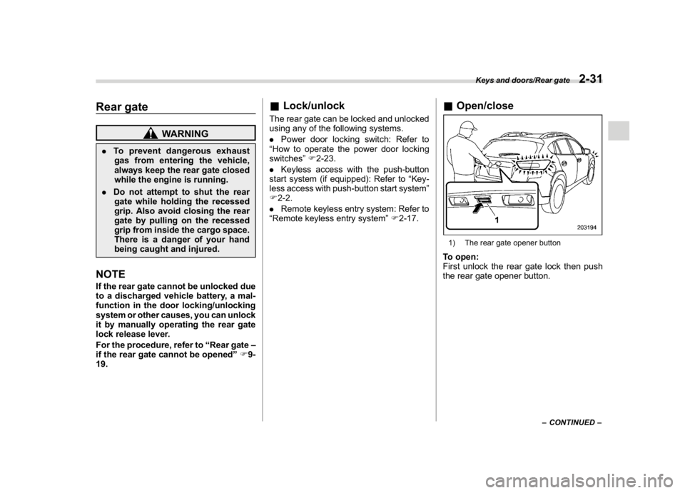
&Open/close1) The rear gate opener buttonTo open:
First unlock the rear gate lock then push
the rear gate opener button.
–CONTINUED–
Keys and doors/Rear gate
2-31
2
Page 131 of 474
(134,1)
北米Model "A1320BE-C" EDITED: 2017/ 10/ 10
To close:
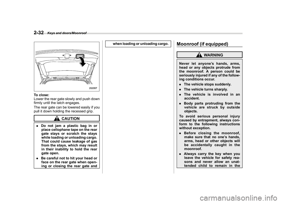
Lower the rear gate slowly and push down
firmly until the latch engages.
The rear gate can be lowered easily if you
pull it down holding the recessed grip.
CAUTION
.Do not jam a plastic bag in or
place cellophane tape on the rear
gate stays or scratch the stays
while loading or unloading cargo.
That could cause leakage of gas
from the stays, which may result
in their inability to hold the rear
gate open.
.Be careful not to hit your head or
face on the rear gate when open-
ing or closing the rear gate andwhen loading or unloading cargo.
Moonroof (if equipped)
WARNING
Never let anyone’s hands, arms,
head or any objects protrude from
the moonroof. A person could be
seriously injured if any of the follow-
ing conditions occur.
.The vehicle stops suddenly.
.The vehicle turns sharply.
.The vehicle is involved in an
accident.
.Body parts protruding from the
vehicle are struck by outside
objects.
To avoid serious personal injury
caused by entrapment, always con-
form to the following instructions
without exception.
.Before closing the moonroof,
make sure that no one’s hands,
arms, head or other objects will
be accidentally caught in the
moonroof.
.Always carry the key when you
leave the vehicle for safety rea-
sons and never allow an unat-
tended child to remain in the
Keys and doors/Moonroof
2-32
Page 134 of 474

(139,1)
北米Model "A1320BE-C" EDITED: 2017/ 10/ 10
Ignition switch (models without“keyless
access with push-button start system”) ............ 3-4
Key positions......................................................... 3-4
Key reminder chime............................................... 3-5
Ignition switch light (if equipped)........................... 3-5
Push-button ignition switch (models with
“keyless access with push-button start
system”) ............................................................... 3-6
Safety precautions................................................. 3-6
Operating range for push-button start system........ 3-6
Switching power status.......................................... 3-7
When access key fob does not operate properly.... 3-8
Hazard warning flasher..........................................3-8
Meters and gauges.................................................3-8
Speedometer......................................................... 3-8
Tachometer............................................................ 3-8
Odometer............................................................... 3-9
Double trip meter................................................... 3-9
Fuel gauge............................................................3-10
ECO gauge (if equipped).......................................3-10
Combination meter settings.................................. 3-11
Illumination brightness control............................3-12
Auto dimmer cancel function (if equipped)............3-12
Warning andindicator..........................................3-12
Initial illumination for system check......................3-12
Seatbelt warning light and chime..........................3-13
SRS airbag system warning light...........................3-15
Front passenger’s frontal airbag ON and OFF
indicators...........................................................3-15
CHECK ENGINE warning light/Malfunction
indicator light.....................................................3-15Coolant temperature low indicator light/Coolant
temperature high warning light..........................3-16
Charge warning light............................................3-17
Oil pressure warning light.....................................3-17
Engine low oil level warning light..........................3-18
Windshield washer fluid warning light...................3-18
AT OIL TEMP warning light (CVT models)..............3-18
Low tire pressure warning light
(U.S.-spec. models)............................................3-18
ABS warning light.................................................3-20
Brake system warning light (red)..........................3-21
Low fuel warning light..........................................3-22
Hill start assist warning light/Hill start assist
OFF indicator light.............................................3-22
Door open warning light.......................................3-22
All-Wheel Drive warning light (CVT models)..........3-22
Power steering warning light ................................3-23
Vehicle Dynamics Control warning light/Vehicle
Dynamics Control operation indicator light........3-23
Vehicle Dynamics Control OFF indicator light.......3-24
Warning chimes and warning indicator of the
keyless access with push-button start system
(if equipped)......................................................3-25
Security indicator light..........................................3-29
Select lever/gear position indicator
(CVT models).....................................................3-30
Turn signal indicator lights...................................3-30
High beam indicator light......................................3-30
High beam assist indicator light (green)
(if equipped)......................................................3-30
High beam assist warning indicator (yellow)
(if equipped)......................................................3-30
Instruments and controls
3
Page 135 of 474

(140,1)
北米Model "A1320BE-C" EDITED: 2017/ 10/ 10
Cruise control indicator light (if equipped).............3-31
Cruise control set indicator light (if equipped).......3-31
Automatic headlight beam leveler warning light
(models with LED headlights)..............................3-31
LED headlight warning light (models with LED
headlights)..........................................................3-31
Steering Responsive Headlight warning light/
Steering Responsive Headlight OFF indicator
light (if equipped)................................................3-31
Front fog light indicator light (if equipped) ............3-31
Headlight indicator light (if equipped)....................3-31
Steering responsive fog lights warning indicator/
Steering responsive fog lights OFF indicator
(if equipped).......................................................3-31
X-mode indicator (if equipped)..............................3-32
Hill descent control indicator (if equipped) ............3-32
BSD/RCTA warning indicator (if equipped).............3-32
BSD/RCTA OFF indicator (if equipped)..................3-32
RAB warning indicator (if equipped)......................3-32
RAB OFF indicator light (if equipped)....................3-32
Icy road surface warning indicator (if equipped)....3-32
Combination meter display (color LCD)
(if equipped).......................................................3-33
Basic operation.....................................................3-34
Welcome screen and Good-bye screen..................3-34
Warning screen.....................................................3-35
Telltale screen.......................................................3-35
Basic screens.......................................................3-36
Menu screens.......................................................3-38
Multi-function display (black andwhite).............3-42
Driving information display...................................3-43
Outside temperature indicator...............................3-46X-mode indicator (if equipped)..............................3-47
Clock....................................................................3-47
Multi-function display (color LCD)
(if equipped).......................................................3-47
Features...............................................................3-48
Welcome screen...................................................3-48
Self-check screen.................................................3-48
Interruption screen...............................................3-49
Basic operation....................................................3-49
Basic screens.......................................................3-50
Setting screen......................................................3-57
How to get the source code using the open
source...............................................................3-62
Clock......................................................................3-63
Setting the clock manually....................................3-63
Setting the clock automatically.............................3-66
Regulatory information.........................................3-66
Light control switch.............................................3-66
Precautions and tips.............................................3-66
Headlights............................................................3-67
High/low beam change (dimmer) ...........................3-68
Headlight flasher..................................................3-69
High beam assist function (if equipped)................3-69
Daytime running light system...............................3-72
Steering Responsive Headlight (SRH)
(if equipped).......................................................3-72
Headlight beam leveler
(models with LEDheadlights)..........................3-73
Fog light switch (ifequipped)..............................3-74
Steering responsive fog lights system
(if equipped)......................................................3-74
Instruments and controls
Page 137 of 474
(142,1)
北米Model "A1320BE-C" EDITED: 2017/ 10/ 10
Ignition switch (models with-
out“keyless access with
push-button start system”)
WARNING
.Never turn the ignition switch to
the“LOCK”position while the
vehicle is being driven or towed
because that will lock the steer-
ing wheel, preventing steering
control. And when the engine is
turned off, it takes a much greater
effort than usual to steer.
.Before leaving the vehicle, al-
ways remove the key from the
ignition switch for safety and
never allow an unattended child
to remain in the vehicle. Failure to
follow this procedure could re-
sult in injury to a child or others.
Children could operate the power
windows, the moonroof or other
controls or even make the vehicle
move.
CAUTION
Do not attach a large key holder or
key case to either key. If it banged
against your knees or hands while
you are driving, it could turn the
ignition switch from the“ON”posi-
tion to the“ACC”or“LOCK”posi-
tion, thereby stopping the engine.
Also, if the key is attached to a key
holder or to a large bunch of other
keys, centrifugal force may act on it
as the vehicle moves, resulting in
unwanted turning of the ignition
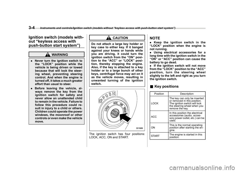
switch.The ignition switch has four positions:
LOCK, ACC, ON and START.
NOTE.Keep the ignition switch in the
“LOCK”position when the engine is
not running.
.Using electrical accessories for a
long time with the ignition switch in the
“ON”or“ACC”position can cause the
battery to go dead.
.If the ignition switch will not move
from the“LOCK”position to the“ACC”
position, turn the steering wheel
slightly to the left and right as you turn
the ignition switch.&Key positions
Position Description
LOCKThe key can only be inserted
or removed in this position.
The ignition switch will lock
the steering wheel when you
remove the key.
ACCIn this position the electrical
accessories (audio, acces-
sory power outlet, etc.) can be
used.
ONThis is the normal operating
position after starting the en-
gine.
STARTThe engine is started in this
position.
Instruments and controls/Ignition switch (models without“keyless access with push-button start system”)
3-4
Page 139 of 474
(144,1)
北米Model "A1320BE-C" EDITED: 2017/ 10/ 10
The light turns off immediately under the
following conditions.
.when the ignition switch is turned to the
“ON”position
.when all doors and the rear gate are
locked using the remote keyless entry
transmitter
Push-button ignition switch
(models with“keyless access
with push-button start sys-
tem”)&Safety precautionsRefer to“Safety precautions”F2-3.&Operating range for push-
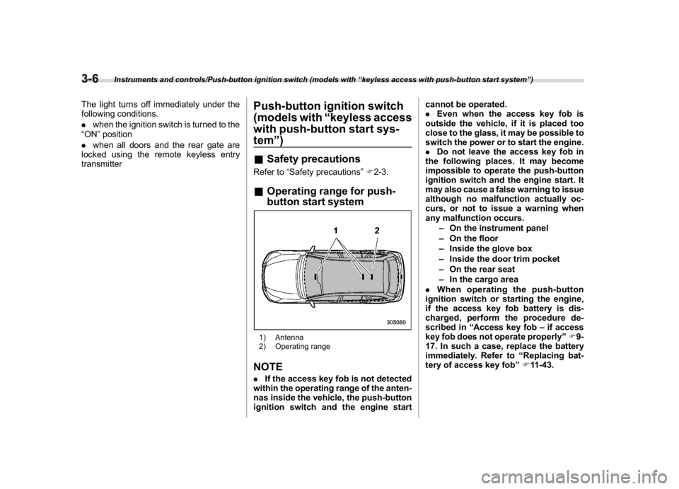
button start system1) Antenna
2) Operating rangeNOTE.If the access key fob is not detected
within the operating range of the anten-
nas inside the vehicle, the push-button
ignition switch and the engine startcannot be operated.
.Even when the access key fob is
outside the vehicle, if it is placed too
close to the glass, it may be possible to
switch the power or to start the engine.
.Do not leave the access key fob in
the following places. It may become
impossible to operate the push-button
ignition switch and the engine start. It
may also cause a false warning to issue
although no malfunction actually oc-
curs, or not to issue a warning when
any malfunction occurs.
–On the instrument panel
–On the floor
–Inside the glove box
–Inside the door trim pocket
–On the rear seat
–In the cargo area
.When operating the push-button
ignition switch or starting the engine,
if the access key fob battery is dis-
charged, perform the procedure de-
scribed in“Access key fob–if access
key fob does not operate properly”F9-
17. In such a case, replace the battery
immediately. Refer to“Replacing bat-
tery of access key fob”F11-43.
Instruments and controls/Push-button ignition switch (models with“keyless access with push-button start system”)
3-6
Page 141 of 474
(146,1)
北米Model "A1320BE-C" EDITED: 2017/ 10/ 10
.If the indicator light on the push-
button ignition switch flashes in green
when the push-button ignition switch is
pressed, steering is locked. When this
occurs, press the push-button ignition
switch while turning the steering wheel
left and right.
!Battery drainage prevention func-
tion
When the push-button ignition switch is left
in the“ACC”or“ON”position for approxi-
mately 1 hour, the push-button ignition
switch will be automatically switched to
“OFF”to prevent the battery from going
dead.&When access key fob does
not operate properlyRefer to“Access key fob–if access key
fob does not operate properly”F9-17.
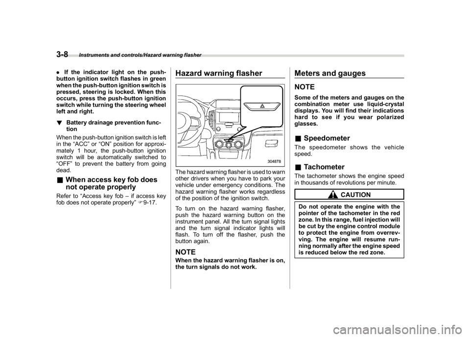
Hazard warning flasherThe hazard warning flasher is used to warn
other drivers when you have to park your
vehicle under emergency conditions. The
hazard warning flasher works regardless
of the position of the ignition switch.
To turn on the hazard warning flasher,
push the hazard warning button on the
instrument panel. All the turn signal lights
and the turn signal indicator lights will
flash. To turn off the flasher, push the
button again.NOTEWhen the hazard warning flasher is on,
the turn signals do not work.
Meters and gaugesNOTESome of the meters and gauges on the
combination meter use liquid-crystal
displays. You will find their indications
hard to see if you wear polarized
glasses.&SpeedometerThe speedometer shows the vehicle
speed.&TachometerThe tachometer shows the engine speed
in thousands of revolutions per minute.
CAUTION
Do not operate the engine with the
pointer of the tachometer in the red
zone. In this range, fuel injection will
be cut by the engine control module
to protect the engine from overrev-
ving. The engine will resume run-
ning normally after the engine speed
is reduced below the red zone.
Instruments and controls/Hazard warning flasher
3-8
Page 144 of 474
(149,1)
北米Model "A1320BE-C" EDITED: 2017/ 10/ 10
If the ECO gauge moves towards the +
side, this indicates better fuel efficiency.NOTE.The ECO gauge shows only an
approximate indication of fuel effi-
ciency.
.After resetting the trip meter, the
average rate of fuel consumption is not
shown until you have driven for 1 mile
(or 1 km). Before that time, the ECO
gauge does not operate.&Combination meter settingsMeter and vehicle settings can be set on
the combination meter.
!Type A combination meter
Various adjustments can be made, such
as switching units shown on the combina-
tion meter and adjusting the warning tone
volume.
While the ignition switch is in the“OFF”
position, each press of TRIP RESET
switch results in items shown in the table
below being switched.
ItemCombination
meter displayPossible
settings
A trip
—
B trip—
Gauge
needle
sweep
function
On/Off
Changing
the unit*mile/km
Warning
volume*Lv. 1/Lv. 2/Lv. 3
*: if available
NOTE.If you switch the units on the combi-
nation meter, the units on the multi-
function display (black and white) also
switches accordingly.
.If either of the following conditions
is met, the combination meter setting
mode will be canceled.
–The driver’s door is opened.
–The TRIP RESET switch is not
operated for approximately 10 sec-
onds or more.!Switching method
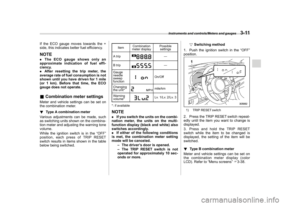
1. Push the ignition switch in the“OFF”
position.
1) TRIP RESET switch2. Press the TRIP RESET switch repeat-
edly until the item you want to change is
displayed.
3. Press and hold the TRIP RESET
switch while the item to be changed is
displayed, the setting of the item will be
switched.
!Type B combination meter
Meter and vehicle settings can be set on
the combination meter display (color
LCD). Refer to“Menu screens”F3-38.
Instruments and controls/Meters and gauges
3-11
3