Page 105 of 204

Underhood Fuses
The Front Power Distribution Center is lo-
cated on the driver’s side of the engine com-
partment. To access the fuses, remove the
cover.The ID number of the electrical component
corresponding to each fuse can be found on
the back of the cover.
Cavity
Maxi Fuse Mini Fuse Description
F01 40 Amp Orange –Electronic Stability Control (ESC) Pump
F02 20 Amp Yellow (3.6 Gasoline
Engine) –
Starter Relay 3.6L (3.6 Gasoline Engine)
F03 30 Amp Green UREA (3.0 Diesel Engine)
F02 50 Amp Red (3.0 Diesel En-
gine) –
Glow Plug Unit (3.0 Diesel Engine)
F04 50 Amp Red (3.6 Gasoline
Engine) –Secondary Power Distribution Center (PDC) (Trans
Power Relay, Vacuum Pump, KL30 for the Shifter
Transmission Module [STM]) (3.6 Gasoline Engine)
F04 40 Amp Orange (3.0 Diesel
Engine) –
Fuel Filter Heater (3.0 Diesel Engine)
F05 30 Amp Green –SELESPEED Pump RELE (3.0 Diesel Engine) —
If Equipped
F06 40 Amp Orange (non A/C)
60 Amp Blue (A/C) –
Engine Cooling Fan - 2nd Speed
F07 50 Amp Red (non A/C)
60 Amp Blue (A/C) –
Engine Cooling Fan - 1st Speed
F08 40 Amp Orange –Passenger Compartment Blower
F09 –15 Amp BlueRear Power Outlet
103
Page 106 of 204

CavityMaxi Fuse Mini Fuse Description
F10 –15 Amp BlueHorn
F11 –15 Amp BlueFuel Pressure Regulator (MPROP)-DRV (3.0 Diesel
Engine) — If Equipped
F14 –20 Amp Yellow Power Outlet
F15 –7.5 Amp Brown USB Charger
F16 –7.5 Amp BrownKL15 Shifter Transmission Module (STM) (3.6),
KL15 Starter Relay Coil (3.6 Gasoline Engine)
F16 –7.5 Amp BrownKL15 Manual Transmission Automated (MTA),
KL15 Gear Selector Unit, KL15 Engine Control Mod-
ule (ECM), KL15 Starter Relay Coil (3.0 Diesel En-
gine)
F17 –20 Amp YellowEngine Control Module (ECM), Injectors (3.6 Gasoline
Engine)
F17 –20 Amp YellowSecondary Loads, Engine Control Module (ECM)
(3.0 Diesel Engine)
F18 –7.5 Amp BrownKL30 Engine Control Module (ECM), KL30 Main Re-
lay Coil (3.6 Gasoline Engine)
F18 –7.5 Amp BrownKL30 Manual Transmission Automated (MTA),
KL30 Engine Control Module (ECM), KL30 Main Re-
lay Coil (3.0 Diesel Engine)
F19 –7.5 Amp Brown A/C Compressor — If Equipped
F20 –30 Amp Green Windshield Wiper
F21 –15 Amp BlueFuel Pump
F22 –20 Amp YellowEngine Control Module (ECM), Ignition Coils
(3.6 Gasoline Engine)
IN CASE OF EMERGENCY
104
Page 107 of 204
CavityMaxi Fuse Mini Fuse Description
F22 –20 Amp YellowEngine Control Module (ECM), Primary Loads
(3.0 Diesel Engine)
F23 –20 Amp Yellow Electronic Stability Control (ESC) Valves
F24 –7.5 Amp BrownKL15 Vacuum Pump Relay Coil (3.6 Gasoline Engine)
— If Equipped
F30 –15 Amp BlueHeated Mirrors
Front PDC Additional Fuses
The additional fuse box is located inside the front PDC Box.
Cavity Mini Fuse Description
F61 20 Amp YellowVacuum Pump (3.6 Gasoline Engine) — If Equipped
F62 30 Amp GreenTransmission Power RELE (3.6 Gasoline Engine) — If Equipped
F64 7.5 Amp Brown Urea Pump (3.0 Diesel Engine) — If Equipped
F65 20 Amp YellowUREA NOX SNS 1-2 + PM SNS (3.0 Diesel Engine) — If Equipped
F66 5 Amp BeigeShifter Transmission Module (STM) (3.6 Gasoline Engine) — If
Equipped
105
Page 108 of 204
Interior Fuses
The interior fuse panel is part of the Body
Control Module (BCM) and is located on the
driver's side under the instrument panel.
CavityMini Fuse Description
F31 5 Amp BeigeINT/A
F34 7.5 Amp Brown Clearance Lights
F36 15 Amp Blue+30 (ACM – TPCU – RRM – DLC)
F37 5 Amp BeigeINT (BRAKE NO – IPC)
F38 15 Amp BlueCentral Locking
F42 5 Amp BeigeINT (BSM – SAS – BRAKE NC)
F43 20 Amp YellowBi-Directional Washer Pump
F47 20 Amp YellowDriver Power Window
F48 20 Amp YellowPassenger Power Window
F49 5 Amp BeigeINT (PAM – CCS – RRM – ECM)
F50 7.5 Amp Brown INT (ORC)
F51 5 Amp BeigeINT (REAR CAMERA-AUX)
F53 5 Amp Beige+30 (IPC)
F90 7.5 Amp Brown Left High Beam
F93 7.5 Amp Brown Right Fog Lamp
IN CASE OF EMERGENCY
106
Page 109 of 204
Right Central Pillar Fuses
The right central pillar fuse panel is located
on the interior side at the base of the passen-
ger side B pillar.
CavityMini Fuse Description
F81 7.5 Amp Brown Seat Heater
F83 20 Amp YellowRear Left Windows Heater
F84 20 Amp YellowRear Right Windows Heater
F86 20 Amp YellowAuxiliary Switch (From Battery) — If Equipped
F87 20 Amp YellowAuxiliary Switch (From Ignition) — If Equipped
107
Page 110 of 204

JACKING AND TIRE CHANGING
WARNING!
• Do not attempt to change a tire on theside of the vehicle close to moving traf-
fic. Pull far enough off the road to avoid
the danger of being hit when operating
the jack or changing the wheel.
• Being under a jacked-up vehicle is dan-
gerous. The vehicle could slip off the
jack and fall on you. You could be
crushed. Never put any part of your body
under a vehicle that is on a jack. If you
need to get under a raised vehicle, take
it to a service center where it can be
raised on a lift.
• Never start or run the engine while the
vehicle is on a jack.
• The jack is designed to be used as a tool
for changing tires only. The jack should
not be used to lift the vehicle for service
purposes. The vehicle should be jacked
on a firm level surface only. Avoid ice or
slippery areas.
Jack Location
The jack and jack tools are stored under the
front passenger seat.
To release the jack kit for it’s storage location,
you must push down and turn the lock knob
1/4 turn counter clockwise to the unlock
position.
CAUTION!
Do not force lock knob over limit. Damage
to lock knob may occur.
Jack Kit Location
Lock Knob
1 — Unlock Position
2 — Lock Position
IN CASE OF EMERGENCY
108
Page 111 of 204
To open the jack kit container you must push
the containers release to separate the top and
bottom.Spare Tire Removal
1. Remove the spare tire before attemptingto jack up the vehicle. Attach the lug bolt
adapter to the winch extension and insert
it into the winch mechanism.
Container Release
Jacking Tools
1 — Jack
2 — Reversible Tool
3 — Tool Handle
4 — Winch Extension
5 — Tow Eye
6 — Wrench Handle
7 — Lug Bolt Adaptor
Jack Tools
1 — Wrench Handle
2 — Lug Bolt Adapter
3 — Winch Extension
109
Page 112 of 204
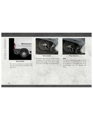
The winch mechanism is located under
the rear of the vehicle to the right of the
spare tire.2. Rotate the wheel wrench handle counter-
clockwise until the spare tire is on the
ground with enough cable slack to allow
you to pull it out from under the vehicle. NOTE:
The winch mechanism is designed for use
with the winch extension tube only. Use of
an air wrench or other power tools is not
recommended and can damage the
winch.
Winch Location
Winch LocationWinch Extension
IN CASE OF EMERGENCY
110