Page 89 of 204
. The gea")
MESSAGEDESCRIPTION
Press Brake Pedal / Startup Delayed This message appears when the key is first turned ON, if the brake pedal is not depressed and/or the gear selector is not in NEUTRAL (N). The gear selector must be in the NEUTRAL (N) position, and thebrake pedal must be pressed, to allow engine cranking. Place the gear selector in NEUTRAL (N) and
apply the brake pedal BEFORE turning the key to the START/AVV position; otherwise, the engine will not crank and the key must be cycled OFF, then back on, before cranking is allowed.
Gear Unavailable This message appears, along with a warning buzzer:
• When it is not possible to change gear due to a fault in the system.
• When, due a fault in the system, it is only possible to engage 1st (1), 2nd (2), 3rd (3) or REVERSE (R).
Contact your authorized dealer if the message continues to appear.
Shift Not Allowed This message may appear when starting the engine at low temperature. In this case the Automated
Manual transmission isn't able to engage first gear, in this situation either use the engine block/
transmission heater or allow the engine to idle in NEUTRAL (N) until the transmission has warmed.
Press Brake And Try Again This message appears accompanied, in some cases, by a warning buzzer, if you attempt to change gear with the vehicle parked without pressing the brake pedal.
To shift the transmission (with key on/engine off), press and hold the brake pedal, move the gear selec- tor to NEUTRAL (N), then move the gear selector to the desired position.
Shift To Neutral This message appears, when the gear selector must be moved to the NEUTRAL (N) position.
When the gear selector is moved to NEUTRAL (N) the message on the display should go off.
Press Brake Pedal This message is shown in the display together with an acoustic signal, when the brake pedal is not
pressed during a starting attempt.
Press Brake Shift to N key to start This message appears, when the drivers door is first opened, to remind to Press the Brake pedal and shift the lever in N to permit the cranking.
87
Page 90 of 204
 models ONLY. DO NOT flat tow any
model with a gasoline engine. Gasoline
engine mode")
Towing The Vehicle
NOTE:
• The information in this section is for Auto-mated Manual Transmission (Diesel En-
gine) models ONLY. DO NOT flat tow any
model with a gasoline engine. Gasoline
engine models MUST be towed with front
wheels OFF the ground. See "Recreational
Towing" for additional information.
• For vehicles equipped with Electric Park Brake, you must ensure that the Auto Park
Brake feature is disabled before being
towed, to avoid inadvertent Electric Park
Brake engagement. The Auto Park Brake
feature can be temporarily disabled by
holding the park brake switch in the off
position while turning the ignition key from
ON/RUN to “OFF”.
• Vehicles with a discharged battery or total electrical failure when the Electric Park
Brake (EPB) is engaged, will need a wheel
dolly or jack to raise the rear wheels off the
ground when moving the vehicle onto a
flatbed. • The manufacturer recommends towing your
vehicle with all four wheels OFFthe ground
using a flatbed.
• Automated Manual transmission vehicles can also be flat towed (all four wheels on
the ground) with the transmission in NEU-
TRAL. Ensure the transmission is in NEU-
TRAL (N) (by checking that the vehicle
moves when pushed) and tow in the same
way as a normal vehicle with a manual
transmission.
If it is not possible to shift the transmission to
NEUTRAL (N), do not flat tow the vehicle and
contact your authorized dealer.
If you must use the accessories (wipers, de-
frosters, etc.) while being towed, the ignition
must be in the ON/RUN mode. NOTE:
For vehicles equipped with Electric Park
Brake the SafeHold feature will engage the
Electric Park Brake whenever the driver's
door is opened (if the ignition is ON and the
brake pedal is released). If you are towing
this vehicle with the ignition in the ON/RUN
position, you must manually disable the Elec-
tric Park Brake each time the driver's door is
opened, by pressing the brake pedal and then
releasing the EPB.
CAUTION!
• DO NOT flat tow any disabled vehicle if
condition is related to the clutch,
transmission or driveline. Additional
damage to the drivetrain could result.
• Towing this vehicle in violation of the
above requirements can cause severe
engine, transmission, or drivetrain
damage. Damage from improper tow-
ing is not covered under the New Ve-
hicle Limited Warranty.
• Ensure that the electric park brake (if
equipped) is released, and remains re-
leased, while being towed.STARTING AND OPERATING
88
Page 91 of 204
 up to the maximum speed
of 100 mph (160 km/h).
The Speed Control Lever is locate")
SPEED CONTROL
When engaged, the Speed Control takes over
accelerator operations at speeds greater than
25 mph (40 km/h) up to the maximum speed
of 100 mph (160 km/h).
The Speed Control Lever is located on the left
side of the steering column.NOTE:
In order to ensure proper operation, the
Speed Control System has been designed to
shut down if multiple Speed Control func-
tions are operated at the same time. If this
occurs, the Speed Control System can be
reactivated by rotating the Speed Control
ON/OFF center ring and resetting the desired
vehicle set speed.
To Activate
Rotate the center ring upward on the Speed
Control lever to turn the system on. The Cruise
Indicator Light in the instrument cluster dis-
play will illuminate. To turn the system off,
rotate the center ring upward a second time.
The Cruise Indicator Light will turn off. The
system should be turned off when not in use.
WARNING!
Leaving the Speed Control system on when
not in use is dangerous. You could acci-
dentally set the system or cause it to go
faster than you want. You could lose con-
trol and have an accident. Always leave the
system off when you are not using it.
To Set A Desired Speed
Turn the Speed Control on. When the vehicle
has reached the desired speed, move the
Speed Control lever upward (SET +) and
release. Release the accelerator and the ve-
hicle will operate at the selected speed.
NOTE:
The vehicle should be traveling at a steady
speed and on level ground before moving the
Speed Control lever upward (SET +).
To Vary The Speed Setting
To Increase Speed
When the Speed Control is set, you can in-
crease speed by tapping the Speed Control
lever up (SET +).
The driver's preferred units can be
selected through the radio settings if
equipped. Refer to ”Uconnect Settings” in
“Multimedia” at www.mopar.com/en-us/care/
owners-manual.html (U.S. Residents) or
www.owners.mopar.ca (Canadian Residents)
for more information. The speed increment
shown is dependant on the chosen speed unit
of U.S. (mph) or Metric (km/h):
Speed Control Lever
1 — Resume
2 — Set/Accel
3 — On/Off
4 — Decel
89
Page 92 of 204

• Tapping the Speed Control lever up (SET +)once will result in a 1 mph increase in set
speed. Each subsequent tap of the lever
results in an increase of 1 mph.
• If the lever is")
U.S. Speed (mph)
• Tapping the Speed Control lever up (SET +)once will result in a 1 mph increase in set
speed. Each subsequent tap of the lever
results in an increase of 1 mph.
• If the lever is continually held up, the set speed will continue to increase until the
lever is released, then the new set speed
will be established.
Metric Speed (km/h)
• Tapping the Speed Control lever up (SET +) once will result in a 1 km/h increase in set
speed. Each subsequent tap of the lever
results in an increase of 1 km/h.
• If the lever is continually held up, the set speed will continue to increase until the
lever is released, then the new set speed
will be established.
To Decrease Speed
When the Speed Control is set, you can de-
crease speed by tapping the Speed Control
lever down (-). The driver's preferred units can be
selected through the radio settings if
equipped. Refer to ”Uconnect Settings” in
“Multimedia” at www.mopar.com/en-us/care/
owners-manual.html (U.S. Residents) or
www.owners.mopar.ca (Canadian Residents)
for more information. The speed increment
shown is dependant on the chosen speed unit
of U.S. (mph) or Metric (km/h):
U.S. Speed (mph)
• Tapping the Speed Control lever down (-)
once will result in a 1 mph decrease in set
speed. Each subsequent tap of the lever
results in a decrease of 1 mph.
• If the lever is continually held down, the set speed will continue to decrease until the
lever is released, then the new set speed
will be established.
Metric Speed (km/h)
• Tapping the Speed Control lever down (-) once will result in a 1 km/h decrease in set
speed. Each subsequent tap of the lever
results in a decrease of 1 km/h. • If the lever is continually held down, the set
speed will continue to decrease until the
lever is released, then the new set speed
will be established.
To Accelerate For Passing
Press the accelerator as you would normally.
When the pedal is released, the vehicle will
return to the set speed.
Using Speed Control On Hills
The transmission may downshift on hills to
maintain the vehicle set speed.
NOTE:
The Speed Control system maintains speed
up and down hills. A slight speed change on
moderate hills is normal.
On steep hills, a greater speed loss or gain
may occur so it may be preferable to drive
without Speed Control.
WARNING!
Speed Control can be dangerous where the
system cannot maintain a constant speed.
Your vehicle could go too fast for the con-
STARTING AND OPERATING
90
Page 93 of 204

WARNING!
ditions, and you could lose control and
have an accident. Do not use Speed Con-
trol in heavy traffic or on roads that are
winding, icy, snow-covered or slippery.
To Resume Speed
To resume a previously set speed, push the
RES button and release. Resume can be used
at any speed above 20 mph (32 km/h) up to
the maximum speed of 100 mph (160 km/h).
To Deactivate
A soft tap on the brake pedal, pushing the
RES button, or normal brake pressure while
slowing the vehicle will deactivate Speed
Control without erasing the set speed
memory. Rotating the center ring upward to
turn the system off or turning the ignition
switch OFF erases the set speed memory.
PARKSENSE REAR PARK ASSIST
If an obstacle is behind the vehicle when
REVERSE gear is engaged, an audible alert is
activated.The tones emitted by the loudspeaker inform
the driver that the vehicle is approaching an
obstacle. The pauses between the tones are
directly proportional to the distance from the
obstacle. Pulses emitted in quick succession
indicate the presence of a very close ob-
stacle. A continuous tone indicates that the
obstacle is less than 12 inches (30 cm) away.
PARKVIEW REAR BACK-UP CAMERA
You can see an on-screen image of the rear of
your vehicle whenever the gear selector is put
into REVERSE. The ParkView Rear Back-Up
Camera image is displayed on the touch-
screen display located on the center stack of
the instrument panel.
NOTE:
If the touchscreen display appears foggy,
clean the camera lens located on the top rear
of the vehicle below the center light.
WARNING!
Drivers must be careful when backing up
even when using the Rear Back-Up Cam-
era. Always check carefully behind your
WARNING!
vehicle, and be sure to check for pedestri-
ans, animals, other vehicles, obstructions,
or blind spots before backing up. You are
responsible for the safety of your surround-
ings and must continue to pay attention
while backing up. Failure to do so can
result in serious injury or death.
REFUELING THE VEHICLE — GAS
ENGINE
The gas cap is located behind the fuel filler
door on the left side of the vehicle. If the gas
cap is lost or damaged, be sure the replace-
ment cap is for use with this vehicle.
WARNING!
• Never have any smoking materials lit in
or near the vehicle when the fuel door is
open or the tank is being filled.
• Never add fuel when the engine is run-
ning. This is in violation of most state
and federal fire regulations and may
91
Page 94 of 204

WARNING!
cause the “Malfunction Indicator Light”
to turn on.
• A fire may result if fuel is pumped into a
portable container that is inside of a
vehicle. You could be burned. Always
place fuel containers on the ground
while filling.
CAUTION!
• Damage to the fuel system or emissionscontrol system could result from using
an improper fuel tank filler tube cap.
• A poorly fitting fuel filler cap could let
impurities into the fuel system.
• A poorly fitting fuel filler cap may cause
the “Malfunction Indicator Light (MIL)”
to turn on.
• To avoid fuel spillage and overfilling, do
not “top off” the fuel tank after filling.
When the fuel nozzle “clicks” or shuts
off, the fuel tank is full. NOTE:
• When the fuel nozzle “clicks” or shuts off,
the fuel tank is full.
• Tighten the fuel filler cap until you hear a “clicking” sound. This is an indication that
the fuel filler cap is properly tightened.
• If the gas cap is not tightened properly, the MIL may come on. Be sure the gas cap is
tightened every time the vehicle is
refueled.Materials Added To Fuel
Designated TOP TIER
Detergent Gasoline
contains a higher level
of detergents to fur-
ther aide in minimiz-
ing engine and fuel
system deposits. When
available, the usage of
Top Tier Detergent gasoline is recommended.
Visit www.toptiergas.com for a list of TOP
TIER Detergent Gasoline Retailers. Indiscriminate use of fuel system cleaning
agents should be avoided. Many of these
materials intended for gum and varnish re-
moval may contain active solvents or similar
ingredients. These can harm fuel system gas-
ket and diaphragm materials.
REFUELING THE VEHICLE — DIESEL
ENGINE
The fuel cap is located behind the fuel filler
door on the left side of the vehicle. If the fuel
cap is lost or damaged, be sure the replace-
ment cap is for use with this vehicle.
CAUTION!
It is extremely important to avoid any con-
tamination of the Diesel Exhaust Fluid
(DEF) with diesel fuel or other petroleum
products. Ensure that the DEF filler cap is
in place and completely tightened before
opening or filling the diesel fuel tank.
STARTING AND OPERATING
92
Page 95 of 204

CAUTION!
To avoid fuel spillage and overfilling, do
not “top off” the fuel tank after filling.NOTE:
• When the fuel nozzle “clicks” or shuts off,
the fuel tank is full.
• Tighten the fuel filler cap until you hear a “clicking” sound. This is an indication that
the fuel filler cap is properly tightened.
• Make sure that the fuel filler cap is tight- ened each time the vehicle is refueled.
WARNING!
A fire may result if fuel is pumped into a
portable container that is on a truck bed.
You could be burned. Always place fuel
containers on the ground while filling.
Diesel Exhaust Fluid
Your vehicle is equipped with a Selective
Catalytic Reduction system to meet the very
stringent diesel emissions standards required
by the Environmental Protection Agency.
The purpose of the SCR system is to reduce
levels of NOx (oxides of nitrogen emitted from
engines) that are harmful to our health and
the environment to a near-zero level. Small
quantities of Diesel Exhaust Fluid (DEF) is injected into the exhaust upstream of a cata-
lyst where, when vaporized, it converts smog-
forming nitrogen oxides (NOx) into harmless
nitrogen (N2) and water vapor (H2O), two
natural components of the air we breathe.
You can operate with the comfort that your
vehicle is contributing to a cleaner, healthier
world environment for this and generations to
come.
System Overview
This vehicle is equipped with a Diesel Ex-
haust Fluid (DEF) injection system and a
Selective Catalytic Reduction (SCR) catalyst
to meet the emission requirements.
The DEF injection system consists of the
following components:
• DEF tank
• DEF pump
• DEF injector
• Electronically-heated DEF lines
• NOx sensors
• Temperature sensors
• SCR catalyst
Fuel/DEF Fill Locations
1 — Diesel Fuel Fill Location
2 — Diesel Exhaust Fluid (DEF) Fill
Location
93
Page 96 of 204

The DEF injection system and SCR catalyst
enable the achievement of diesel emissions
requirements; while maintaining outstanding
fuel economy, drivability, torque and power
ratings.
Refer to “Instrument Cluster Display” in
“Getting To Know Your Instrument Panel” for
system messages and warnings.
NOTE:
• Your vehicle is equipped with a DEF injec-tion system. You may occasionally hear an
audible clicking noise from under the ve-
hicle at a stop. This is normal operation.
• The DEF pump will run for a period of time after engine shutdown to purge the DEF
system. This is normal operation and may
be audible from under the vehicle.
Adding Diesel Exhaust Fluid
NOTE:
Driving conditions (altitude, vehicle speed,
load, etc.) will effect the amount of DEF that
is used by your vehicle.
DEF Fill Procedure
NOTE:
Refer to “Fluids And Lubricants” in “Techni-
cal Specifications” for the correct fluid type.
CAUTION!
It is extremely important to avoid any con-
tamination of the diesel fuel with Diesel
Exhaust Fluid (DEF). Ensure that the die-
sel fuel filler cap is in place and com-
pletely tightened before opening or filling
the DEF.
1. Remove cap from DEF filler neck (located on drivers side of the vehicle in the fuel
door).
2. Insert DEF fill adapter/nozzle into DEF tank filler neck.
CAUTION!
•To avoid DEF spillage, and possible dam-
age to the DEF tank from overfilling, do
not “top off” the DEF tank after filling.
• DO NOT OVERFILL. DEF will freeze be- low 12ºF (-11ºC). The DEF system is
designed to work in temperatures below
the DEF freezing point, however, if the
tank is overfilled and freezes, the system
could be damaged.
Fuel/DEF Fill Locations
1 — Diesel Fuel Fill Location
2 — Diesel Exhaust Fluid (DEF) Fill
Location
STARTING AND OPERATING
94
 1
1 2
2 3
3 4
4 5
5 6
6 7
7 8
8 9
9 10
10 11
11 12
12 13
13 14
14 15
15 16
16 17
17 18
18 19
19 20
20 21
21 22
22 23
23 24
24 25
25 26
26 27
27 28
28 29
29 30
30 31
31 32
32 33
33 34
34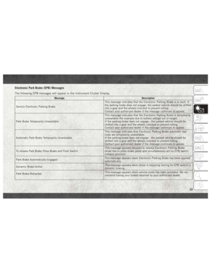 35
35 36
36 37
37 38
38 39
39 40
40 41
41 42
42 43
43 44
44 45
45 46
46 47
47 48
48 49
49 50
50 51
51 52
52 53
53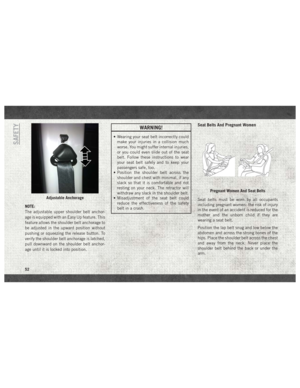 54
54 55
55 56
56 57
57 58
58 59
59 60
60 61
61 62
62 63
63 64
64 65
65 66
66 67
67 68
68 69
69 70
70 71
71 72
72 73
73 74
74 75
75 76
76 77
77 78
78 79
79 80
80 81
81 82
82 83
83 84
84 85
85 86
86 87
87 88
88 89
89 90
90 91
91 92
92 93
93 94
94 95
95 96
96 97
97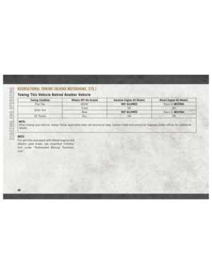 98
98 99
99 100
100 101
101 102
102 103
103 104
104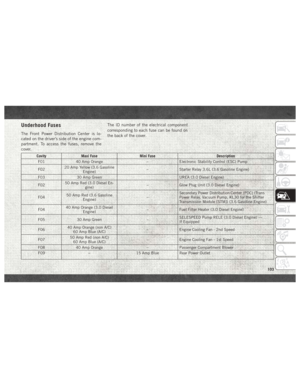 105
105 106
106 107
107 108
108 109
109 110
110 111
111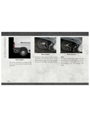 112
112 113
113 114
114 115
115 116
116 117
117 118
118 119
119 120
120 121
121 122
122 123
123 124
124 125
125 126
126 127
127 128
128 129
129 130
130 131
131 132
132 133
133 134
134 135
135 136
136 137
137 138
138 139
139 140
140 141
141 142
142 143
143 144
144 145
145 146
146 147
147 148
148 149
149 150
150 151
151 152
152 153
153 154
154 155
155 156
156 157
157 158
158 159
159 160
160 161
161 162
162 163
163 164
164 165
165 166
166 167
167 168
168 169
169 170
170 171
171 172
172 173
173 174
174 175
175 176
176 177
177 178
178 179
179 180
180 181
181 182
182 183
183 184
184 185
185 186
186 187
187 188
188 189
189 190
190 191
191 192
192 193
193 194
194 195
195 196
196 197
197 198
198 199
199 200
200 201
201 202
202 203
203