2018 FIAT FIORINO Owner handbook (in English)
-
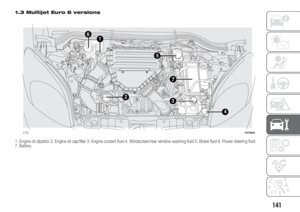
 1
1 -
 2
2 -
 3
3 -
 4
4 -
 5
5 -
 6
6 -
 7
7 -
 8
8 -
 9
9 -
 10
10 -
 11
11 -
 12
12 -
 13
13 -
 14
14 -
 15
15 -
 16
16 -
 17
17 -
 18
18 -
 19
19 -
 20
20 -
 21
21 -
 22
22 -
 23
23 -
 24
24 -
 25
25 -
 26
26 -
 27
27 -
 28
28 -
 29
29 -
 30
30 -
 31
31 -
 32
32 -
 33
33 -
 34
34 -
 35
35 -
 36
36 -
 37
37 -
 38
38 -
 39
39 -
 40
40 -
 41
41 -
 42
42 -
 43
43 -
 44
44 -
 45
45 -
 46
46 -
 47
47 -
 48
48 -
 49
49 -
 50
50 -
 51
51 -
 52
52 -
 53
53 -
 54
54 -
 55
55 -
 56
56 -
 57
57 -
 58
58 -
 59
59 -
 60
60 -
 61
61 -
 62
62 -
 63
63 -
 64
64 -
 65
65 -
 66
66 -
 67
67 -
 68
68 -
 69
69 -
 70
70 -
 71
71 -
 72
72 -
 73
73 -
 74
74 -
 75
75 -
 76
76 -
 77
77 -
 78
78 -
 79
79 -
 80
80 -
 81
81 -
 82
82 -
 83
83 -
 84
84 -
 85
85 -
 86
86 -
 87
87 -
 88
88 -
 89
89 -
 90
90 -
 91
91 -
 92
92 -
 93
93 -
 94
94 -
 95
95 -
 96
96 -
 97
97 -
 98
98 -
 99
99 -
 100
100 -
 101
101 -
 102
102 -
 103
103 -
 104
104 -
 105
105 -
 106
106 -
 107
107 -
 108
108 -
 109
109 -
 110
110 -
 111
111 -
 112
112 -
 113
113 -
 114
114 -
 115
115 -
 116
116 -
 117
117 -
 118
118 -
 119
119 -
 120
120 -
 121
121 -
 122
122 -
 123
123 -
 124
124 -
 125
125 -
 126
126 -
 127
127 -
 128
128 -
 129
129 -
 130
130 -
 131
131 -
 132
132 -
 133
133 -
 134
134 -
 135
135 -
 136
136 -
 137
137 -
 138
138 -
 139
139 -
 140
140 -
 141
141 -
 142
142 -
 143
143 -
 144
144 -
 145
145 -
 146
146 -
 147
147 -
 148
148 -
 149
149 -
 150
150 -
 151
151 -
 152
152 -
 153
153 -
 154
154 -
 155
155 -
 156
156 -
 157
157 -
 158
158 -
 159
159 -
 160
160 -
 161
161 -
 162
162 -
 163
163 -
 164
164 -
 165
165 -
 166
166 -
 167
167 -
 168
168 -
 169
169 -
 170
170 -
 171
171 -
 172
172 -
 173
173 -
 174
174 -
 175
175 -
 176
176 -
 177
177 -
 178
178 -
 179
179 -
 180
180 -
 181
181 -
 182
182 -
 183
183 -
 184
184 -
 185
185 -
 186
186 -
 187
187 -
 188
188 -
 189
189 -
 190
190 -
 191
191 -
 192
192 -
 193
193 -
 194
194 -
 195
195
 CHILD SAFETY DEVICE
9)
This system prevents opening the
sliding side doors from the inside.
The device can be engaged only with
the sliding side door open fig. 12:
position 1 - device engaged (door
lo")
 WARNING
5)Before opening a door, ensure that you
can do it in conditions of safety.
6)The right sliding side door cannot be
opened with the fuel flap open during
refuelling.
7)Do not leave the sliding")
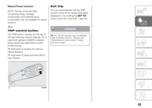
 FOLDAWAY PASSENGER
SEAT
(for versions/markets, where provided)
The passenger seat can be folded
away on some versions.
IMPORTANT Move the seat only when
there are no rear passengers.
Seat folding
To f")
 WARNING
12)All adjustments must be made with the
vehicle stationary.
13)Once you have released the
adjustment lever, always check that the
seat is locked on the guides by trying
to move it back and fo")
 WARNING
16)All adjustments must be carried out
only with the vehicle stationary and the
engine off. Head restraints must be
adjusted so that the head, rather than the
neck, rests on them. Only in this")
 REAR VIEW
MIRRORS
INTERIOR MIRROR
(for versions/markets, where provided)
The mirror is fitted with a safety device
that causes its release in the event of
a violent impact with the passenger.
Lever A")
 EXTERIOR LIGHTS
The left stalk fig. 32 includes the
exterior light controls.
The exterior lights can only be switched
on when the ignition key is at
MAR-ON.
The instrument panel and the various
dashbo")
 Lane change function
If you wish to signal a lane change,
place the left stalk in the unstable
position for less than half a second.
The direction indicator on the side
selected will be activated for")