Page 105 of 196
 Operation at low temperatures
In order to avoid these problems,
different types of diesel are distributed
according to the season: summer type,
winter type and arctic type (cold/
mountain areas). If r")
Operation at low temperatures
In order to avoid these problems,
different types of diesel are distributed
according to the season: summer type,
winter type and arctic type (cold/
mountain areas). If refuelling with diesel
whose specifications are not suitable
for the usage temperature, it is
advisable to mix PETRONAS
DURANCE DIESEL ART additive in the
proportions shown on the container
with the fuel. Pour the additive into the
tank before the fuel.
When using or parking the vehicle for a
long time in the mountains or cold
areas, it is advisable to refuel using
locally available diesel fuel.
In this case, it is also advisable to keep
the tank over 50% full.
REFUELLING CAPACITY
To ensure that you fill the tank
completely, top up twice after the first
click of the fuel supply gun. Further
top-ups could cause faults in the fuel
feeding system.
FUEL TANK CAP
Opening
1) Open the flap A fig. 115 by pulling it
outwards, keep the cap B fig. 115
still, insert the ignition key in the lock
and turn it anticlockwise.2) Turn the cap anticlockwise and
remove it.
The cap has a device C fig. 115 that
attaches it to the flap so it cannot
be lost. When refilling, attach the plug
to the flap, as shown.
Closing
1) Fit the cap (complete with key) and
turn it clockwise until it clicks once
or more.
2) Turn the key clockwise and extract it,
then close the flap.
The sealing may cause a slight pressure
increase in the tank. A little breathing
off, while slackening the cap is
absolutely normal.METHANE ENGINES
(NATURAL POWER)
METHANE GAS FILLER
The methane filler is located near the
petrol filler fig. 116.
It has a check valve, located in the filler
body.
To access the filler, undo the capAfig.
116 turning it anticlockwise.
The profile of fillerBfig. 117 for refilling
is the universal type, compatible with
Italian and "NGV1" standards.
115F0T0068
116F0T0360
117F0T0336
103
Page 106 of 196
 In some European countries adapters
are considered ILLEGAL (e.g. in
Germany).
For service stations with cubic metre
(m
3) nozzles (pressure differential)
the check valves must be released by
deliverin")
In some European countries adapters
are considered ILLEGAL (e.g. in
Germany).
For service stations with cubic metre
(m
3) nozzles (pressure differential)
the check valves must be released by
delivering a small amount of methane to
measure the residual pressure in the
cylinder.
The plates (provided with the vehicle
documentation) contain the date for the
first inspection of the cylinders.
34)
Fuels - identification of
vehicle compatibility.
Graphic symbol for
consumer information in
accordance with
EN16942
The symbols shown below aid
recognising the correct fuel type to be
used on your vehicle. Before
proceeding with refuelling, check the
symbols inside the fuel filler flap (where
provided) and compare them with the
symbols shown on the fuel pump
(where provided).Symbols for petrol fuelled vehicles
E5: Unleaded petrol containing up to
2.7% (m/m) oxygen and with maximum
5.0% (V/V) ethanol compliant with
EN228.
E10: Unleaded petrol containing up to
3.7% (m/m) oxygen and with maximum
10.0% (V/V) ethanol compliant with
EN228.
Symbols for diesel fuelled vehicles
B7: Diesel containing up to 7% (V/V) of
FAME (Fatty Acid Methyl Esters)
compliant withEN590.
B10: Diesel containing up to 10% (V/V)
of FAME (Fatty Acid Methyl Esters)
compliant withEN16734.Symbols for petrol/methane fuelled
vehicles
E5: Unleaded petrol containing up to
2.7% (m/m) oxygen and with maximum
5.0% (V/V) ethanol compliant with
EN228.
E10: Unleaded petrol containing up to
3.7% (m/m) oxygen and with maximum
10.0% (V/V) ethanol compliant with
EN228.
CNG: Automotive compressed
methane compliant withEN16723.
WARNING
105)Do not bring naked flames or lit
cigarettes near to the fuel filler: fire risk.
Keep your face away from the fuel filler to
prevent breathing in harmful vapours.
104
STARTING AND DRIVING
Page 107 of 196
 WARNING
32)For diesel engines, use only diesel fuel
for motor vehicles in accordance with
EN590 European specifications. The use of
other products or mixtures may damage
the engine beyond repair and
c")
WARNING
32)For diesel engines, use only diesel fuel
for motor vehicles in accordance with
EN590 European specifications. The use of
other products or mixtures may damage
the engine beyond repair and
consequently invalidate the warranty, due
to the damage caused. If you accidentally
introduce other types of fuel into the tank,
do not start the engine. Empty the tank.
If the engine has been run for even an
extremely limited amount of time, you must
not only drain the fuel tank, but the rest of
the supply circuit as well.
33)You must not open the right sliding side
door with the fuel cap open while
refuelling. Check that the fuel cap is closed
while opening/closing the sliding side
door.
34)Methane refuelling stations are not
authorised to refill the cylinders when the
inspection date has expired. The check
valve prevents the methane from flowing
back to the fuel filler.
TOWING TRAILERS
IMPORTANT NOTES
The vehicle must be equipped with a
type-approved tow hook and adequate
electrical system to tow trailers.
Installation should be carried out by
specialised technicians who will issue
the required papers for travelling on
roads.
Install any specific and/or additional
door mirrors as specified by the
Highway Code.
Remember that, when towing a trailer,
steep hills are harder to climb, braking
distances increase and overtaking
takes longer depending on the overall
weight of the trailer.
Engage a low gear when driving
downhill, rather than constantly using
the brake.
The weight of the trailer on the vehicle
tow hook will reduce the loading
capacity of the vehicle by the same
amount.
To make sure that the maximum
towable weight is not exceeded (given
in the vehicle registration document)
account should be taken of the fully
laden trailer, including accessories and
luggage.Do not exceed the speed limits specific
to each country you are driving in, in
the case of vehicles towing trailers.
In all cases, the top speed must not
exceed 80 km/h.
IMPORTANT For Natural Power
versions, trailers cannot be towed so
there are no provisions for fitting a tow
hook.
106) 107)
WARNING
106)The ABS with which the vehicle may
be equipped will not control the trailer's
braking system. Particular caution is
required on slippery roads.
107)Never modify the braking system of
the vehicle to control the trailer brake. The
trailer braking system must be fully
independent from the hydraulic system of
the vehicle.
105
Page 108 of 196
IN AN EMERGENCY
A punctured tyre or a burnt-out bulb?
At times, a problem may interfere
with our journey.
The pages on emergencies can help
you to deal with critical situations
independently and with calm.
In an emergency we recommend that
you call the toll-free number found
on the Warranty Booklet.
It is also possible to call the 00 800
3428 0000 freephone number to
search the nearest Fiat Dealership.HAZARD WARNING LIGHTS...........107
REPLACING A WHEEL ...................107
FIX & GO AUTOMATIC KIT ..............111
CHANGING A BULB .......................113
REPLACING AN EXTERIOR BULB ..116
REPLACING INTERIOR BULBS ......119
REPLACING FUSES........................120
JUMP STARTING ............................127
FUEL CUT-OFF SYSTEM ................128
TOWING THE VEHICLE ..................128
106
IN AN EMERGENCY
Page 109 of 196
 HAZARD WARNING
LIGHTS
They are turned on by pressing switch
A fig. 118, regardless of the ignition
key's position.
The
andwarning lights on the
instrument panel turn on when this
device is enabled")
HAZARD WARNING
LIGHTS
They are turned on by pressing switch
A fig. 118, regardless of the ignition
key's position.
The
andwarning lights on the
instrument panel turn on when this
device is enabled. Press switch A again
to turn the lights off.
IMPORTANT The use of hazard warning
lights is governed by the highway
code of the country you are in. Comply
with legal requirements.
Emergency braking (for versions/
markets where provided)
In the event of emergency braking, the
hazard warning lights turn on
automatically together with the
and
warning lights on the instrument
panel. The function switches off
automatically when the nature of the
braking changes.
REPLACING A
WHEEL
Combi/Cargo version -T he vehicle
is originally equipped with the Fix&Go
Automatic quick tyre repair kit (see
instructions in the next section). As an
alternative, the vehicle may have a
normal-sized spare wheel.
Wheel changing and correct use of the
jack and spare wheel call for some
precautions, as listed below.
108) 109) 110) 111) 112) 113) 114)
35) 36)
JACK
Please note that:
the jack weight is 1.76 kg;
the jack requires no adjustment;
the jack cannot be repaired and in
the event of a fault it must be replaced
by another genuine one;
no tool other than its cranking
device may be fitted on the jack.
WHEEL REPLACEMENT
PROCEDURE
To change a wheel, proceed as follows:
stop the vehicle in a position that is
not dangerous for oncoming traffic
where you can change the wheel safely.
The ground must be flat and sufficiently
compact;
switch off the engine and pull the
handbrake;
engage first gear or reverse;
wear the reflective safety jacket
(compulsory by law in certain countries)
before getting out of the vehicle;
indicate that the vehicle has broken
down using the devices required by
the law in the current country (e.g.
warning triangle, hazard lights, etc.);
for Cargo versions: lift lever A fig.
119 and move the left front set
backrest forward to retrieve the tool
bag located behind the backrest:
release the elastic strap and take the
tool bag to the wheel to be changed;
for Combi versions: open the rear
swing doors, take the tool bag fig. 120
located on the left of the boot by
releasing the elastic straps and take to
the wheel to be replaced;
118F0T0049
119F0T0119
107
Page 110 of 196
take wheel spanner B fig. 121 and
the extension with pentagonal fitting C;
inside the load area, fit extension C
on bolt A; use spanner B to lower the
wheel by unwinding the wire;
use the wheel dismantling spanner B
to remove the wheel from the vehicle
fig. 122;
unscrew knob D fig. 123 and release
the rim from bracket E, removing it
from the hole of the rim;
for vehicles with alloy rims, remove
the hub cap;
loosen the fixing bolts of the wheel
to be replaced by about one turn, using
the spanner provided;
for wheels with steel rims, remove
the wheel cap;
turn the jack to open it partially and
then position it under the vehicle at
the references A fig. 124 near the wheel
to be replaced;
turn the jack to open it until the
groove A fig. 125 of the jack is correctly
inserted in the lower profile B on the
side member;
120F0T0206
122F0T0168
121F0T0922
123F0T0923
124F0T0125
125F0T0126
108
IN AN EMERGENCY
Page 111 of 196
 warn anybody nearby that the
vehicle is about to be lifted. They must
stay clear and not touch the vehicle
until it is back on the ground;
operate the jack and lift the vehicle
until the wheel is seve")
warn anybody nearby that the
vehicle is about to be lifted. They must
stay clear and not touch the vehicle
until it is back on the ground;
operate the jack and lift the vehicle
until the wheel is several centimetres off
the ground. When turning the crank,
ensure that it rotates freely in order
to avoid grazing your hands against the
ground. The moving components of
the jack (screws and joints) can also
cause injuries: avoid touching them. If
you come into contact with lubricating
grease, clean yourself thoroughly;
fully loosen the four fastening bolts
and remove the wheel;
make sure the contact surfaces
between spare wheel and hub are
clean so that the fastening bolts will not
come loose;
fit the standard wheel by inserting
the first bolt two threads B fig. 126 into
the hole nearest to the inflation valve
A;
fit the hub cap, making sure that the
symbol
(on the cup) aligns with the
inflation valve, and then insert the other
three bolts;
tighten the bolts using the spanner
provided;
for cars with alloy rim, fit the hub
cap;
turn the jack handle to lower the
vehicle, and remove the jack;
use the wrench provided to fasten
the bolts completely in a criss-cross
fashion as shown in fig. 127.
At the end of the operation
fix bracket A fig. 128 to the wheel
after passing it through the hole, insert
the threaded pin into one of the bolt
holes and secure by tightening knob B;
for vehicles with allow wheels,
remove the adapter D fig. 129 and
introduce the bracket into the adapter
D, insert the pin into the hole and
secure with the knob F;
position the wheel vertically and rest
the fitted adaptor on the inside of the
rim, then using the screws provided fix
the wheel to the adaptor fig. 130.
Tighten the screws with the wheel
spanner;
126F0T0282
127F0T0128
128F0T0924
129F0T0925
109
Page 112 of 196
 check that the position of the
replaced wheel under the platform is
correct (the lifting system is equipped
with a clutch to limit the end of the
stroke, incorrect positioning may
jeopardise safety;)")
check that the position of the
replaced wheel under the platform is
correct (the lifting system is equipped
with a clutch to limit the end of the
stroke, incorrect positioning may
jeopardise safety;)
lift the wheel by fastening the bolt A
fig. 121;
put jack and tools back in the
specific tool bag;
reposition the tool bag behind the
left seat (Cargo versions) or in the boot
(Combi versions);
secure the tool box to the hooks.
WARNING
108)If left in the passenger compartment,
the punctured wheel and jack constitute
a serious risk to the safety of occupants in
the event of accidents or sharp braking.
Therefore, always place both the jack and
punctured wheel in the dedicated housing.109)It is extremely dangerous to attempt
to change a wheel on the side of the
vehicle next to the driving lane: make sure
that the vehicle is at a sufficient distance
from the road, to avoid being run over.
110)The spare wheel (for versions/
markets, where provided) is specifically for
your vehicle. Therefore, it must not be
used on other models. Do not use spare
wheels of other models on your vehicle.
The spare wheel must be used only in an
emergency. Use of the spare wheel must
be strictly reduced to the necessary
minimum.
111)Use your hazard lights, warning
triangle, etc to show that your vehicle is
stationary. Passengers should get out
of the vehicle, particularly if it is heavily
loaded, and wait for the wheel to be
changed away from the traffic. If you are on
a slope or uneven surface, place wedges
or other suitable objects under the wheels
to secure the vehicle. Have the wheel
repaired and refitted as soon as possible.
Do not apply grease to the bolt threads
before fitting: they could come unscrewed.
112)The jack is a tool developed and
designed only for changing a wheel, if a
tyre gets punctured or damaged, on the
vehicle with which it is supplied or on other
vehicles of the same model. Any other
use, e.g. to jack up other vehicle models or
different things, is strictly prohibited. Never
use it to carry out maintenance or repairs
under the vehicle or to change summer/
winter wheels and vice versa: we advise
you to contact a Fiat Dealership. Never go
under the raised vehicle: use it only in
the positions indicated.Do not use the jack for loads higher than
the one shown on its label. Never start the
engine with vehicle raised. If the vehicle
is raised more than necessary, everything
can become more unstable, with the risk of
the vehicle dropping violently. Thus, lift the
vehicle only as needed in order to access
the spare wheel.
113)Incorrect hub cap assembly may
cause it to come off when the vehicle is
moving. Never tamper with the inflation
valve. Never introduce tools of any kind
between rim and tyre. Check tyre and
space-saver wheel pressures regularly,
referring to the values shown in the
"Technical data" chapter.
114)Never use the space-saver spare
wheel for more than strictly necessary and
never exceed 80 km/h. On the space-saver
wheel there is an orange label,
summarising the main warnings regarding
usage restrictions. Never remove or cover
the label. Warning! For temporary use only!
80 km/h max.! Replace by standard wheel
as soon as possible.
WARNING
35)When turning the jack handle make
sure that it can turn freely without scraping
your hand against the ground. The moving
components of the jack ("worm screw"
and joints) can also cause injuries: do not
touch them. If you come into contact
with lubricating grease, clean yourself
thoroughly.
36)Contact a Fiat Dealership as soon as
possible to have the correct tightening
of the fixing bolts checked.
130F0T0926
110
IN AN EMERGENCY
 1
1 2
2 3
3 4
4 5
5 6
6 7
7 8
8 9
9 10
10 11
11 12
12 13
13 14
14 15
15 16
16 17
17 18
18 19
19 20
20 21
21 22
22 23
23 24
24 25
25 26
26 27
27 28
28 29
29 30
30 31
31 32
32 33
33 34
34 35
35 36
36 37
37 38
38 39
39 40
40 41
41 42
42 43
43 44
44 45
45 46
46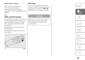 47
47 48
48 49
49 50
50 51
51 52
52 53
53 54
54 55
55 56
56 57
57 58
58 59
59 60
60 61
61 62
62 63
63 64
64 65
65 66
66 67
67 68
68 69
69 70
70 71
71 72
72 73
73 74
74 75
75 76
76 77
77 78
78 79
79 80
80 81
81 82
82 83
83 84
84 85
85 86
86 87
87 88
88 89
89 90
90 91
91 92
92 93
93 94
94 95
95 96
96 97
97 98
98 99
99 100
100 101
101 102
102 103
103 104
104 105
105 106
106 107
107 108
108 109
109 110
110 111
111 112
112 113
113 114
114 115
115 116
116 117
117 118
118 119
119 120
120 121
121 122
122 123
123 124
124 125
125 126
126 127
127 128
128 129
129 130
130 131
131 132
132 133
133 134
134 135
135 136
136 137
137 138
138 139
139 140
140 141
141 142
142 143
143 144
144 145
145 146
146 147
147 148
148 149
149 150
150 151
151 152
152 153
153 154
154 155
155 156
156 157
157 158
158 159
159 160
160 161
161 162
162 163
163 164
164 165
165 166
166 167
167 168
168 169
169 170
170 171
171 172
172 173
173 174
174 175
175 176
176 177
177 178
178 179
179 180
180 181
181 182
182 183
183 184
184 185
185 186
186 187
187 188
188 189
189 190
190 191
191 192
192 193
193 194
194 195
195 IN AN EMERGENCY
A punctured tyre or a burnt-out bulb?
At times, a problem may interfere
with our journey.
The pages on emergencies can help
you to deal with critical situations
independently and with")
 take wheel spanner B fig. 121 and
the extension with pentagonal fitting C;
inside the load area, fit extension C
on bolt A; use spanner B to lower the
wheel by unwinding the wire;
use the wheel disman")