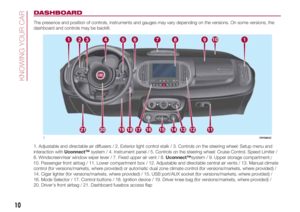
Page 129 of 268

If you are on a slope or uneven surface,
place the wedge provided under the wheel
(see the instructions on the next pages).
124)The vehicle's driving characteristics
will be modified with the space-saver wheel
fitted. Avoid violent acceleration and
braking, abrupt steering and fast cornering.
The overall duration of the space-saver
wheel is of about 3000 km, after which the
relevant tyre must be replaced with another
one of the same type. Never install a
standard tyre on a rim that is designed for
use with a space-saver wheel. Have the
wheel repaired and refitted as soon as
possible. Using two or more space-saver
wheels at the same time is forbidden.
Do not grease the threads of the stud bolts
before fitting them: they might slip out.
125)The jack is a tool developed and
designed only for changing a wheel, if a
tyre gets punctured or damaged, on the
vehicle with which it is supplied or on other
vehicles of the same model. Any other
use, e.g. to jack up other vehicle models or
different things, is strictly prohibited. Never
use it to carry out maintenance or repairs
under the vehicle or to change summer/
winter wheels and vice versa: we advise
you to contact a Fiat Dealership. Never go
under the raised vehicle: use it only in
the positions indicated. Do not use the jack
for loads higher than the one shown on
its label. Never start the engine with car
raised. If the vehicle is raised more than
necessary, everything can become more
unstable, with the risk of the vehicle
dropping violently. Thus, lift the car only as
needed in order to access the space-saver
spare wheel.126)The space-saver wheel cannot be
fitted with snow chains. If a front (drive) tyre
is punctured and chains are needed, use
a standard wheel from the rear axle and
install the space-saver wheel on the rear
axle. In this way, with two normal drive
wheels at the front axle, it is possible to use
snow chains.
127)When turning the jack handle make
sure that it can turn freely without scraping
your hand against the ground. The moving
components of the jack ("worm screw"
and joints) can also cause injuries: do not
touch them. If you come into contact
with lubricating grease, clean yourself
thoroughly.
128)If the hub cap is not fitted correctly, it
may come off when the car is travelling.
Never tamper with the inflation valve. Never
introduce tools of any kind between rim
and tyre. Check tyre and space-saver
wheel pressures regularly, complying with
the values given in the "Technical
specifications" chapter.
129)At the end of the operation of
raising/locking the space-saver wheel
device, the spanner must be extracted,
taking care NOT to turn it in the wrong
direction to facilitate the extraction of the
spanner itself, so as to prevent the
attachment device from being released and
the lack of safe restraint.
WARNING
62)Contact a Fiat Dealership as soon as
possible to have the correct tightening
of the wheel stud bolts checked.
“Fix&Go Automatic”
KIT
130) 131)
63)2)
DESCRIPTION
The Fix&Go Automatic kit is located in
the boot, inside a dedicated container.
The container is also equipped with
a screwdriver, the tow hook and the
funnel for refuelling in an emergency. To
access the kit, open the boot door,
remove the load platform and lift the
covering carpet.
LPG versions
The kit is located in a bag fixed to the
boot lining by means of Velcro.
The kit fig. 130 contains:
one cartridge A containing sealant
and fitted with: transparent tube for
injecting the sealant 4 and sticker
C with the wording MAX 80 km/h / 50
mph to be placed in a clearly visible
position (e.g. on the dashboard) after
repairing the tyre;
a compressor B;
one leaflet containing instructions for
using the kit;
127
Page 130 of 268

a pair of gloves located in the hose
compartment of the cartridge D.
REPAIR PROCEDURE
Proceed as follows:
stop the car in a position that is not
dangerous for oncoming traffic where
you can change the wheel safely. The
car must be stopped in a lay-by,
car-park or parking or service area, and
the ground must be as level as possible
and sufficiently compact;
switch off the engine, pull up the
handbrake and engage the 1stgear or
reverse. Make sure that any passengers
get out of the car and go to a safe
place where they will not obstruct traffic
or be exposed to the risk of injury.
Wear the reflective safety jacket
(compulsory by law) before getting out
of the car;
Insert the cartridge A fig. 130
containing the sealant in the proper
compartment of the compressor B,
pressing it down hard. Remove the
adhesive speed label C and apply it in a
visible position;
wear the gloves;
remove the cap from the tyre valve
and connect and firmly tighten the
transparent tube of the sealing fluid D
fig. 130. If a 250 ml cartridge is present
the housing of the transparent tube is
provided with removable ring to
facilitate extraction. Make sure that the
ON-OFF button F fig. 132 is in the off
position (button not pressed);
insert the electrical connector E fig.
131 in the 12 V current socket of the
car and start the engine;
operate the compressor by pressing
the ON-OFF button F fig. 132. When
the pressure shown in the "Wheels"
paragraph in the “Technical data”
chapter or on the specific label appears
on the pressure gauge G, stop the
compressor by pressing the ON-OFF
button again;
disconnect the cartridge A fig. 133
from the compressor, by pressing
the release button H and lifting the
cartridge upwards.
130F0Y0624C
131F0Y0625C
132F0Y0626C
133F0Y0627C
128
IN AN EMERGENCY
Page 131 of 268

If the pressure gauge G fig. 132
indicates a pressure lower than 1.8 bar
/ 26 psi 15 minutes after starting the
compressor, switch off the compressor,
disconnect the sealing fluid tube D fig.
130 from the tyre valve and remove
the cartridge A from the compressor.
Move the car by approximately 10
metres to allow the distribution of the
sealant. Stop the vehicle safely, operate
the handbrake and restore pressure
using the black inflation pipe L fig. 134
to reach the required pressure. If also
in this case, the pressure is lower
than 1.8 bar / 26 psi 15 minutes after
turning on, do not resume driving
but contact a Fiat Dealership.
After driving for about 8 km / 5 miles
fig. 135, move the car to a safe and
suitable area and engage the
handbrake. Take the compressor and
restore pressure using the black
inflation tube L fig. 134.If the pressure shown is higher than 1.8
bar / 26 psi, restore the pressure and
drive safely to a Fiat Dealership as soon
as possible. If, however, the pressure
is lower than 1.8 bar / 26 psi, do not
resume driving but contact a Fiat
Dealership.
INFLATION PROCEDURE
Proceed as follows:
stop the car safely, as described
above, and operate the handbrake;
extract the black inflation tube and
screw it firmly onto the tyre valve. Then
follow the instructions below.
Press the air release button M fig. 132
to adjust any excessive tyre pressure.CARTRIDGE
REPLACEMENT
Proceed as follows:
only use original cartridges, which
can be purchased from the Fiat
Dealership;
to remove the cartridge, press the
release button and lift it (see description
above).
WARNING
130)WARNING Do not exceed 80 km/h.
Avoid sudden acceleration or braking. The
kit provides a temporary repair, therefore
the tyre must be examined and repaired by
a specialist as soon as possible. Before
using the kit, ensure that the tyre is not
excessively damaged and that the rim is in
good condition, otherwise do not use it
and call roadside assistance. Do not
remove foreign bodies from the tyre. Do
not let the compressor turned on for more
than 20 consecutive minutes - overheating
hazard.
131)The information required by the
applicable regulation is indicated on the
Fix&Go kit package label. Carefully read the
label on the cartridge before use, avoid
improper use. The kit should be used by
adults and cannot be used by children.
134F0Y0629C
135F0Y0628C
129
Page 132 of 268

WARNING
63)The sealant is effective with external
temperatures of between -40°C and
+55°C. The sealant has an expiry date. It is
possible to repair tyres which have been
damaged on tread up to a diameter of
6 mm. Show the cartridge and the label to
the personnel charged with handling the
tyre treated with the tyre repair kit.
WARNING
2)Dispose of the bottle and the sealant
liquid properly. Have the sealing fluid and
the bottle disposed of in compliance
with national and local regulations.
REPLACING A BULB
132) 133)64) 65)
GENERAL
INSTRUCTIONS
Before replacing a bulb check the
contacts for oxidation.
Burnt bulbs must be replaced by
others of the same type and power.
After replacing a headlight bulb,
always check that alignment of the light
beam is correct.
when a light is not working, check
that the corresponding fuse is intact
before replacing a bulb. For the location
of fuses, refer to the paragraph
"Replacing fuses" in this chapter.IMPORTANT When the weather is cold
or damp or after heavy rain or washing,
the surface of headlights or rear lights
may steam up and/or form drops of
condensation on the inside. This is
a natural phenomenon due to the
difference in temperature and humidity
between the inside and the outside
of the glass which does not indicate a
fault and does not compromise the
normal operation of lighting devices.
The mist disappears quickly when the
lights are turned on, starting from
the centre of the diffuser, extending
progressively towards the edges.
130
IN AN EMERGENCY
Page 133 of 268
TYPES OF BULBS
UseType Power
Dipped/main beam headlights H7 55W
Daytime running lights (DRL) LED + bulb W21W 21W
Front side lights LED –
Rear side lights/Brake lights P21/5W 21W/5W
Front direction indicators PY21W 21W
Side direction indicators WY5W 5W
Rear direction indicators P21W 21W
Third brake light LED –
Fog lights H11 55W
Reversing light W16W 16W
Rear fog light W16W 16W
Number plate C5W 5W
Front ceiling light C5W 5W
Front roof lights (sun visors) C5W 5W
Luggage compartment light W5W 5W
Glove compartment light C5W 5W
Rear ceiling lights C5W 5W
131
Page 134 of 268

FRONT UPPER LIGHT
CLUSTER
This contains the bulbs for the direction
indicators and dipped headlights.
The bulbs are arranged as follows fig.
136:
A: direction indicators
B: dipped beam headlights
DIRECTION INDICATORS
To replace the bulb, proceed as follows:
remove cover A fig. 136;
turn bulb holder B fig. 137
anticlockwise, extract bulb C and
replace it;
refit the new bulb on the bulb holder,
making sure it is correctly locked;
refit the bulb holder in its housing
and turn it clockwise, until the locking
click is heard;
then refit the cover A fig. 136.DIPPED BEAM
HEADLIGHTS
To replace the bulb, proceed as follows:
remove cover B fig. 136;
remove the connector and bulb
holder C fig. 138 unit, releasing it
outwards;
remove bulb D from connector E
and replace it;
refit the new bulb on the connector,
making sure it is correctly locked;
refit the connector and bulb holder C
unit in its housing;
then refit the cover B fig. 136.
FRONT LOWER LIGHT
CLUSTER
This contains the bulbs for the main
beams and side lights/daytime running
lights (DRL).
The bulbs are arranged as follows fig.
139:
C: main beam headlights
D: side lights/daytime running lights
(DRL)
MAIN BEAM HEADLIGHTS
To replace the bulb, proceed as
follows:
steer the wheel completely inwards;
undo the screws A fig. 140 and
remove the flap B;
remove cover C fig. 139;
136F0Y0021C
137F0Y0022C
138F0Y0023C
139F0Y0499C
132
IN AN EMERGENCY
Page 135 of 268

remove the connector and bulb
holder D unit, releasing it outwards;
remove the bulb E from connector F
and replace it;
refit the new bulb on the connector,
making sure it is correctly locked;
refit the connector and bulb holder D
unit in its housing;
finally refit cover C.SIDE LIGHTS/DAYTIME
RUNNING LIGHTS (DRL)
Side lights/daytime running lights
(DRL)
(versions with LED lights)
For light replacement, contact a Fiat
Dealership.
Daytime running lights (DRL)
(versions with incandescent bulb)
To replace the bulb, proceed as follows:
steer the wheel completely inwards;
undo the screws A fig. 140 and
remove the flap B;
remove cover D fig. 139;
turn bulb holder E fig. 142
anticlockwise, extract bulb F from
connector G and replace it;
refit the new bulb on the connector,
making sure it is correctly locked;
refit the bulb holder unit E in its
housing and turn it clockwise, until the
locking click is heard;
finally refit cover D.
SIDE DIRECTION
INDICATORS
To replace the bulb, proceed as follows:
adjust the lens A fig. 143 to
compress in the internal catch B fig.
144, then pull the cluster outwards;
turn the bulb holder C anticlockwise,
extract bulb D and replace it;
refit the bulb holder C in the lens A
fig. 143and turn it clockwise;
refit the cluster making sure that the
internal catch B fig. 144 clips into
position.
140F0Y0145C
141F0Y0025C
142F0Y0026C
143F0Y0147C
133
Page 136 of 268
FOG LIGHTS
(for versions/markets, where provided)
To replace the bulb, proceed as follows:
steer the wheel completely inwards;
undo the screws A fig. 145 and
remove the flap B;
release the clip C fig. 146 and
disconnect the electrical connector D;
turn and remove the bulb holder E;
release the bulb and replace it;
refit the new lamp and carry out the
procedure described previously in
reverse.
REAR LIGHT CLUSTERS
These contain the bulbs for the side
lights, brake lights and direction
indicators.
To replace the bulbs, proceed as
follows:
take the Allen key A fig. 147
provided;
operate tab B fig. 148 and remove
protective cover C (located in the side
area of the luggage compartment);
use Allen key A to unscrew fixing
devices D fig. 149 of the rear light
cluster;
extract the light cluster by removing
it with both hands in the direction
indicated by the arrows fig. 150;
144F0Y0171C
145F0Y0148C
146F0Y0033C147F0Y0149C
148F0Y0150C
149F0Y0258C
134
IN AN EMERGENCY