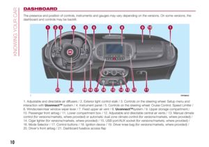
Page 113 of 268

SPEED LIMITER
(for versions/markets, where provided)
This a driving assistance device that
limits the speed of the car as set by the
driver. The maximum speed can be
set both with vehicle stationary and in
motion. The speed is programmable
between 30 and 130 km/h.
When the device is active, the car
speed depends on the pressure at the
accelerator pedal, until the
programmed speed limit is reached
(see "Speed limit programming"
paragraph).
DEVICE ACTIVATION
Press button A fig. 101 on the steering
wheel.If the Cruise Control function was
previously activate, press button A
twice. The first pressing with switch off
the previously activated function and
the second will activate the Speed
Limiter.
ACTIVATING/
DEACTIVATING THE
DEVICE
Activating the device
The device can be activated in two
ways:
by pressing the RES button;
by pressing and releasing the
SET+/SET – buttons
If the device is activated by means of
the RES button, if the set speed is
lower than the car speed, an acoustic
and visual warning is activated, while
the sped is limited after approximately
20 seconds.
The device is activated by means of the
SET+/SET – buttons only if the car
speed is comprised between 30 and
130 km/h. In this case, the device
is activated at the current speed.
Device deactivation: press the CANC
button.
The activation of the device is indicated
by the
green symbol on the display.
In case of deactivation, instead, the
symbol appears white.Device reactivation: press the RES
button.
DISENGAGEMENT OF
THE DEVICE
To deactivate the device press button A
fig. 101.
Device automatic deactivation: the
device deactivates automatically in
the event of fault in the system. Go to a
Fiat Dealership if the problem persists.
IMPORTANT Activating the Cruise
Control will deactivate the Speed
Limiter.
101F0Y0620C
111
Page 114 of 268

MODE SELECTOR
(for versions/markets, where provided)
By turning the ring on the knob located
on the central tunnel, in front of the
gear lever (see figure), the device can
be used to select three different car
response modes to be selected
according to driving style and road
conditions:
ring in position A: “NORMAL”
mode
ring in position B: “TRACTION +”
mode
ring in position C: “GRAVITY
CONTROL” mode
The selected driving mode is indicated
by the LED located near the selection
and an indication on the display.“NORMAL” MODE
It is a driving mode aimed at comfort
and safety in normal grip and driving
conditions.
“Normal” is the default mode: the
following screen on the display when
this mode is active fig. 103.
“TRACTION +” MODE
This system is designed to assist
setting off on slippery surfaces (e.g.
snow, ice, mud, etc.) by distributing the
drive force in optimal manner on the
front axle.By braking the wheels with poor grip (or
those slipping more than the others),
the system transfers the drive force to
the wheels which have more grip on the
ground.
Activating the “Traction +” system will
generate a front axle differential lock
effect to optimise traction on uneven
surfaces by means of the braking
system.
Activation
Turn the ring rightwards (position B fig.
102) and hold in this position for half
a second and in all cases until the
corresponding LED lights up and the
“Traction +” mode activation indicator
appears on the display fig. 104.
Once released, the ring-nut returns to
the central position.
This system operations at speed under
30 km/h: over this speed it is
automatically deactivated and is
reactivated as soon as the speed drops
under 30 km/h. In this case, the LED
on the ring remains on.
102F0Y0600C103F0Y0669C
112
STARTING AND DRIVING
Page 115 of 268

Turning off
To deactivate “Traction +” mode and go
back to “Normal” mode, turn the ring
leftwards and hold this position for half
a second. In this case, the LED related
to “Normal” mode will light up and
the indication that “Traction +” mode
has been deactivated will appear on the
display.
IMPORTANT If “Traction +” or “Normal”
modes are selected when the engine
is stopped, the mode will be maintained
when starting again.IMPORTANT In “Traction +” mode, the
Start&Stop system is temporarily
deactivated (LED on the Start&Stop
system button on). To reactivate the
Start&Stop system with “Traction +”
mode on, press the Start&Stop button
located on the dashboard. The
Start&Stop system will be activated
again when “Traction +” mode is
deactivated.
IMPORTANT The City Brake Control -
“Collision Mitigation” system is
temporarily deactivated when “Traction
+” mode is deactivated. Temporary
deactivation of the system is indicated
by the warning light
on the
instrument panel (together with a
message on the display). The City
Brake Control - “Collision Mitigation”
system will be activated again when
“Traction +” mode is deactivated.
“GRAVITY CONTROL” FUNCTION
This driving function aims at maintaining
a constant speed when driving
downhill on a steel gradient. Noise and
vibrations from the wheel sides (brakes)
are normal when the function is active.IMPORTANT The function can only be
selected with “Traction +” mode active,
engine running, handbrake released
and driver side door correctly closed.
Activation
To activate the function, go to a speed
slower than 25 km/h.
After reaching the desired speed,
release the accelerator and brake
pedals completely. If you want to
increase/decrease the speed, press the
accelerator and brake pedals again.
Activation
Turn the ring rightwards (position C fig.
102) and hold in this position for half
a second and in all cases until the
corresponding LED lights up and the
“Gravity Control” mode activation
indicator appears on the display fig.
105.
Once released, the ring-nut returns to
the central position. The “Gravity
Control” is ready to work when the
“Gravity Control” function is selected.
Turning off
To deactivate “Gravity Control” mode,
turn the ring leftwards and hold this
position for half a second.
104F0Y0667C
113
Page 116 of 268

In this case, the LED related to
“Traction +” mode will light up and the
indication that “Gravity Control” function
has been deactivated will appear on
the display.
The “Gravity Control” function is always
deactivated when the engine is started.
IMPORTANT NOTES
IMPORTANT DO NOT USE THE
DEVICE WITH THE TRANSMISSION IN
NEUTRAL.IMPORTANT The function is available at
speeds from 7 km/h to 25 km/h.
IMPORTANT It is important to engage a
gear suitable for the set speed, to
prevent the engine from stalling. While
the “Gravity Control” system is
operating it is always possible to take
control of the car again by pressing the
brake and accelerator pedals. If the
function is not available when an
attempt to activate it made, it could
mean that the brakes are overheated.
In this case, wait a few minutes before
using the function again.
IMPORTANT The function will be
deactivated in case of brake
overheating by gradually releasing the
braking pressure leaving the driver
in control of the car. Deactivation of the
function is indicated by the flashing of
the symbol
on the display (in
combination with a dedicated message)
and acoustic warning. To reactivate
the function, wait for the braking
system to cool down and then operate
on the ring nut located on the central
tunnel again.IMPORTANT The “Gravity Control”
function is deactivated when exceeding
25 km/h and at speeds lower than 50
km/h it remains enabled to be
reactivated when the speed drops
under 25 km/h. In this case, the
indication on the display is switched off
and the LED on the ring stays on. If
the speed exceeds 50 km/h, the
“Gravity Control” function is completely
deactivated and all automatic actions
on the brakes by the function are
disabled. To reactivate it, turn the ring
nut again when the speed is again
below 25 km/h. It is advisable to use
the function in low gears (first, second
and third).
IMPORTANT On flat city streets, it is
advisable to deactivate the “Gravity
Control” function because at speeds
slower than 25 km/h the function could
be reactivated in particular conditions
(setting off, shifting gear or on speed
bumps without using the accelerator
pedal).
105F0Y0668C
114
STARTING AND DRIVING
Page 117 of 268

PARKING SENSORS
114)58)
SENSORS
The sensors are located in the rear
bumper fig. 106 or fig. 107 (500L
WAGON version) and their function is to
detect the presence of any obstacles
near the rear of the car and inform
the driver through an intermittent
acoustic signal and visual indication on
the instrument panel display.
INDICATIONS ON THE
DISPLAY
The parking system indications appear
on the instrument panel display (see
figure).The system indicates the presence of
an obstacle by displaying a single arc in
one of the possible areas, in
accordance with the distance of the
object and the position in relation to the
car. If the obstacle is detected in the
rear central area, a single arc will be
displayed as the obstacle approaches,
first constant, then flashing, in addition
to an acoustic signal.
ACTIVATION/
DEACTIVATION
The sensors are automatically activated
when reverse gear is engaged. As the
obstacle behind the car gets closer
to the car, the acoustic signal becomes
more frequent.
OPERATION WITH A
TRAILER
The operation of the sensors is
automatically deactivated when the
trailer electric cable plug is inserted in
the tow hook socket of the car. The
sensors are automatically reactivated
when the trailer's cable plug is
removed.
106F0Y0616C
107F0Y0140C
108F0Y0966C
115
Page 118 of 268

IMPORTANT NOTES
When parking, take the utmost care
over obstacles that may be above
or under the sensor.
Under certain circumstances, objects
close to the car are not detected by the
system and could therefore cause
damage to the car or be damaged
themselves.
Some conditions may influence the
performance of the parking sensors:
the presence of ice, snow, mud
or think paint on the sensor surface
may cause reduced sensitivity of the
sensor itself and therefore reduce
the system performance;
mechanical interference (e.g.
washing the car, rain, strong wind, hail)
may cause the sensor to detect a
non-existent obstacle ("echo
interference");
the presence of ultrasonic systems
(e.g. pneumatic brake systems of
trucks or pneumatic drills) near the car
could alter the signals sent by the
sensor;
the variation in sensor position,
caused by variation in ride (due
to suspension component wear),
changing tyres, overloaded car, or
tuning that lowers the car, for example,
may affect parking sensor system
performance.
WARNING
114)Parking and other dangerous
manoeuvres are, however, always the
driver’s responsibility. While carrying out
these manoeuvres, always make sure that
no people (especially children) or animals
are in the area concerned. The parking
sensors are an aid for the driver, but the
driver must never allow their attention
to lapse during potentially dangerous
manoeuvres, even those executed at low
speeds.
WARNING
58)For correct operation of the system,
sensors must always be clean from mud,
dirt, snow or ice. Be careful not to scratch
or damage the sensors while cleaning
them. Avoid using dry, rough or hard
cloths. The sensors should be washed
using clean water with the addition of car
shampoo if necessary. When using special
washing equipment such as high pressure
jets or steam cleaning, clean the sensors
very quickly keeping the jet more than
10 cm away. Also, do not apply stickers to
the sensors.
REAR BACKUP
CAMERA
(PARKVIEW® REAR
BACKUP CAMERA)
115)59)
The camera is located on the tailgate
fig. 109.
CAMERA ACTIVATION/
DEACTIVATION
Use the "Settings" menu of the
Uconnect™system. When the camera
is activated, whenever reverse is
engaged the image of the area behind
the car appears on theUnconnect™
system display.
109F0Y0618C
116
STARTING AND DRIVING
Page 119 of 268

SYMBOLS AND
MESSAGES ON THE
DISPLAY
When displayed, the static line grid
illustrates the width of the vehicle.
The grid shows separate areas,
permitting the distance from the rear of
the car to be detected.
The various coloured areasfig. 110
indicate the distance from the rear part
of the car.
Red area (A): 0–30 cm
Yellow area (B): 30–100 cm
Green area (C):1mormore
The "red area A" contains a horizontal
line D, which indicates the obstacle the
car is approaching. Therefore, take
special care when reversing.IMPORTANT When parking, take the
utmost care over obstacles that may be
above or under the operating range of
the camera.
WARNING
115)Parking and other potentially
dangerous manoeuvres are, however,
always the driver’s responsibility. While
carrying out these manoeuvres, always
make sure that no people (especially
children) or animals are in the area
concerned. The camera is an aid for the
driver, but the driver must never allow
his/her attention to lapse during potentially
dangerous manoeuvres, even those
executed at low speeds. Always keep a
slow speed, so as to promptly brake in the
case of obstacles.
WARNING
59)It is vital, for correct operation, that the
camera is always kept clean and free
from any mud, dirt, snow or ice. Be careful
not to scratch or damage the camera
while cleaning it. Avoid using dry, rough or
hard cloths. The camera must be washed
using clean water, with the addition of
car shampoo if necessary. In washing
stations which use steam or high-pressure
jets, clean the camera quickly, keeping
the nozzle more than 10 cm away from the
sensors. Also, do not apply stickers to
the camera.
TOWING TRAILERS
116) 117) 118)
INSTALLING A TOW
HOOK
The towing device should be fastened
to the body by specialised technicians
according to any additional and/or
integrative information supplied by the
Manufacturer of the device.
The towing device must meet current
regulations with reference to Directive
94/20/EC and subsequent
amendments.
For any version the towing device used
must be right for the towable weight
of the car on which it is to be installed.
For the electrical connection a standard
connector should be used which is
generally placed on a special bracket
normally fastened to the towing device,
and a special ECU for external trailer
light control must be installed on the
vehicle.
For the electrical connection,a7or13
pin 12 V DC connection is to be used
(CUNA/UNI and ISO/DIN Standards).
Follow the reference instructions
provided by the car Manufacturer
and/or the tow device Manufacturer.
110F0Y0617C
117
Page 120 of 268

IMPORTANT NOTES
For towing caravans or trailers the car
must be fitted with an approved tow
hook and an adequate electrical
system. Installation must be carried out
by specialised technicians.
Install any specific and/or additional
door mirrors as specified by the
Highway Code.
Remember that, when towing a trailer,
steep hills are harder to climb, braking
distances increase and overtaking
takes longer depending on the overall
weight of the trailer.
Engage a low gear when driving
downhill, rather than constantly using
the brake.
The weight the trailer exerts on the car
tow hook reduces the car's loading
capacity by the same amount. To make
sure that the maximum towable weight
is not exceeded (given in the vehicle
registration document) account should
be taken of the fully laden trailer,
including accessories and luggage.
Do not exceed the speed limits specific
to each country you are driving in, in
the case of vehicles towing trailers.
In any case, the top speed must not
exceed 100 km/h.Any electric brake (or electric winch,
etc.) should be supplied directly by the
battery through a cable with a section
of at least 2.5 mm
2.
In addition to the electrical branches,
the car electrical system can only
be connected to the supply cable for an
electric brake and to the cable for an
internal light for the trailer, not
exceeding 15 W. For connections, use
the preset control unit with a battery
cable with section not less than 2.5
mm
2.
IMPORTANT The use of auxiliary loads
other than external lights (electric brake,
winch, etc.) must take place with
engine running.
IMPORTANT To install a tow hook
contact a Fiat Dealership.
WARNING
116)The ABS with which the car is
equipped will not control the braking
system of the trailer. Particular caution is
required on slippery roads.
117)Never modify the braking system of
the vehicle to control the trailer brake. The
trailer braking system must be fully
independent of the vehicle’s hydraulic
system.
118)After fitting, screw holes must be
sealed to prevent a exhaust gas inlet.
REFUELLING THE
VEHICLE
119) 120) 121)60)
Before refuelling, make sure that the
fuel type is correct. During refuelling
procedure, switch off the engine,
engage handbrake, rotate the ignition
key to STOP and do not smoke.
PETROL ENGINES
Only use unleaded petrol with a number
of octanes (R.O.N.) not lower than 95
(EN228 specification).
DIESEL ENGINES
Only use Diesel for motor vehicles
(EN590 specification).
When using or parking the car for a
long time in the mountains or cold
areas, it is advisable to refuel using
locally available Diesel. In this case, it is
also advisable to keep the tank over
50% full.
REFUELLING
PROCEDURE
Diesel and petrol versions
Proceed as follows:
open the flap A fig. 111 pulling
outwards, insert the nozzle in the filler
and refuel;
118
STARTING AND DRIVING