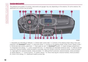
Page 121 of 268

after refuelling, before removing the
dispenser, wait for at least 10 seconds
in order for the fuel to flow inside the
tank;
then remove the dispenser from the
filler and close flap A.
The refuelling procedure described
above is illustrated on the label B fig.
111 located inside the fuel flap. The
label also indicates the fuel type
(UNLEADED FUEL=petrol,
DIESEL=diesel fuel).Flap A is provided with a dust cover
gaiter C fig. 111which prevents
deposits of impurities and dust at the
end of the filler when the flap is closed.
Emergency refuelling
If there is no fuel in the car or the supply
circuit is completely empty, proceed
as follows to reintroduce fuel to the
tank:
open the boot and get the adapter,
located in the toolbox or, depending
on the versions, in the Fix&Go
Automatic container;
open the fuel flap by pulling
outwards, insert the adapted in the filler,
as shown in fig. 112 and refuel;
after refuelling, remove the adapter
and close the flap;
reintroduce the adapter in the box
and put this back in the boot.LPG versions
To refuel, open the fuel flap A fig. 113
and undo the cap B. During the
refuelling operation, give the specific
refuelling adapter C fig. 113 to the LPG
fuel station personnel.
IMPORTANT Depending on the country,
there are various types of adapters for
LPG refuelling pumps. Filler adapter,
supplied with the vehicle and located in
a special case, is specifically designed
for the country in which the vehicle is
sold. If you are in a different country,
find out what type of adaptor is used
there.
IMPORTANT Only use LPG for motor
vehicles.
111F0Y0229C112F0Y0231C
113F0Y0327C
119
Page 122 of 268

Natural Power versions
61)
To refuel, open the flap A fig. 114, undo
the cap B turning anticlockwise and
open the filler C.
The profile of the filler is of the universal
type, compatible with Italian and NGV1
standards. In some European countries
adapters are ILLEGAL (e.g. in
Germany).Fuels - identification of vehicle
compatibility. Graphic symbol for
consumer information in
accordance with EN16942
The symbols shown below facilitated
recognising the correct fuel type to
be used on your car.
Before proceeding with refuelling,
check the symbols inside the fuel filler
flap (where provided) and compare
them with the symbols shown on the
fuel pump (where provided).
Symbols for petrol powered cars
E5: Unleaded petrol containing up
to 2.7% (m/m) oxygen and with
maximum 5.0% (V/V) ethanol compliant
withEN228.
E10: Unleaded petrol containing up to
3.7% (m/m) oxygen and with maximum
10.0% (V/V) ethanol compliant with
EN228.Symbols for diesel powered cars
B7: Diesel containing up to 7% (V/V) of
FAME (Fatty Acid Methyl Esters)
compliant withEN590.
B10: Diesel containing up to 10% (V/V)
of FAME (Fatty Acid Methyl Esters)
compliant withEN16734.
Symbols for petrol/methane bi-fuel
cars
E5: Unleaded petrol containing up to
2.7% (m/m) oxygen and with maximum
5.0% (V/V) ethanol compliant with
EN228.
E10: Unleaded petrol containing up to
3.7% (m/m) oxygen and with maximum
10.0% (V/V) ethanol compliant with
EN228.
CNG: Automotive compressed
methane compliant withEN16723.
114F0Y0254C
115BENZINA-TARGH
116DIESEL-TARGH
117METANO-TARGH
120
STARTING AND DRIVING
Page 123 of 268

Symbols for petrol/LPG bi-fuel cars
E5: Unleaded petrol containing up to
2.7% (m/m) oxygen and with maximum
5.0% (V/V) ethanol compliant with
EN228.
E10: Unleaded petrol containing up to
3.7% (m/m) oxygen and with maximum
10.0% (V/V) ethanol compliant with
EN228.
LPG: Automotive LPG compliant with
EN589.
WARNING
119)Do not apply any object/plug to the
end of the filler which is not provided
for the car. The use of non-compliant
objects/plugs could cause a pressure
increase inside the tank, resulting in
dangerous situations.
120)Do not bring naked flames or lit
cigarettes near to the fuel filler: fire risk.
Keep your face away from the fuel filler to
prevent breathing in harmful vapours.
121)Do not use a mobile phone near the
refuelling pump: risk of fire.
WARNING
60)For diesel engines, only use diesel fuel
for motor vehicles in accordance with
EN590 European specifications. The use of
other products or mixtures may damage
the engine beyond repair and
consequently invalidate the warranty, due
to the damage caused. If you accidentally
introduce other types of fuel into the tank,
do not start the engine. Empty the tank.
If the engine has been run for even an
extremely limited amount of time, you must
not only drain the fuel tank, but the rest of
the supply circuit as well.
61)The other plates (provided with the
vehicle documents) show the date when
the first cylinder inspection/test is due.
Methane refuelling stations are not
authorised to refill the cylinders when the
inspection date has expired.
118GPL-TARGH
121
Page 124 of 268
IN AN EMERGENCY
A punctured tyre or a burnt-out bulb?
At times, a problem may interfere
with our journey.
The pages on emergencies can help
you to deal with critical situations
independently and with calm.
In an emergency we recommend that
you call the freephone number found in
the Warranty Booklet.
It is also possible to call the national or
international universal freephone
number to search for the nearest
Dealership.HAZARD WARNING LIGHTS...........123
REPLACING A WHEEL ...................123
“FIX&GO AUTOMATIC” KIT .............127
REPLACING A BULB ......................130
REPLACING FUSES........................137
JUMP STARTING ............................143
FUEL CUT-OFF SYSTEM ................145
TOWING THE VEHICLE ..................145
122
IN AN EMERGENCY
Page 125 of 268

HAZARD WARNING
LIGHTS
CONTROL
Press the button fig. 119 to switch the
lights on/off. When the hazard warning
lights are on, the
andwarning
lights flash.
Emergency braking
In the event of emergency braking the
hazard warning lights switch on
automatically as well as warning lights
andin the instrument panel.
The lights switch off automatically when
emergency braking ceases.
REPLACING A
WHEEL
122) 123) 124) 125) 128) 127) 126)62)
JACK
Please note that:
the jack weight is 1,76 kg;
the jack requires no adjustment;
the jack cannot be repaired and in
the event of a fault it must be replaced
by another genuine one;
no tool other than its cranking
device may be fitted on the jack.
Maintenance
prevent any dirt from depositing on
the "worm screw";
keep the "worm screw" lubricated;
never modify the jack.
Conditions for non-use
temperatures below −40°C;
on sandy or muddy ground;
on uneven ground;
on steep roads;
in extreme weather conditions:
thunderstorms, typhoons, hurricanes,
blizzards, storms, etc...
in direct contact with the engine or
for repairs under the car;
on boats.WHEEL REPLACEMENT
PROCEDURE
Proceed as follows:
stop the car in a position that is not
dangerous for oncoming traffic where
you can change the wheel safely. The
car must be stopped in a lay-by,
car-park or parking or service area, and
the ground must be as level as possible
and sufficiently compact;
switch off the engine, pull up the
handbrake and engage the 1stgear or
reverse. Make sure that any passengers
get out of the car and go to a safe
place where they will not obstruct traffic
or be exposed to the risk of injury.
Wear the reflective safety jacket
(compulsory by law) before getting out
of the car;
500L versions: open the luggage
compartment and lift up the mat;
500L WAGON versions: open the
luggage compartment and lift up the
"Cargo Magic Space" load platform,
holding it with one hand while you take
out the tool bag.
500L versions: using the wrench A
fig. 120 located in the tool box, loosen
the locking device, take the tool box
B and place it close to the wheel to be
replaced. Then take the space-saver
wheel C;
119F0Y0649C
123
Page 126 of 268

500L WAGON versions: lift up the
tab A fig. 121 of the luggage
compartment mat, take the wrench B
from the tool bag and fit it onto the
device C. Turn the wrench B
anticlockwise to unscrew the
space-saver spare wheel fixing bolt so
that it can be lowered, and use the
wrench to drag the wheel out of the
car;
500L WAGON versions: turn the
device D fig. 122 and release the
space-saver spare wheel from its fixing
support E;
take the spanner A fig. 123 and
loosen the fixing stud bolts by about
one turn. For versions with alloy rims,
shake the car to facilitate detachment
of the rim from the wheel hub;
take the chock from the tool bag
and open it out (see fig. 124);
position the chock behind the wheel
diagonally opposite the one to be
replaced to prevent the car from
moving when it is raised, then fit the
jack underneath the car, next to the
wheel to be replaced;
insert the wrench A fig. 125 to
extend the jack until the top of the jack
B fits correctly into the sidemember
C (next to the mark
on the
sidemember itself);
120F0Y0096C
121F0Y0355C
122F0Y0357C
123F0Y0093C
124F0Y0211C
125F0Y0014C
124
IN AN EMERGENCY
Page 127 of 268

alert any bystander that the car is
about to be raised; all persons should
be kept away from the car and nobody
must touch it until it has been lowered;
fit handle D fig. 125 into the housing
in device A, operate the jack and raise
the vehicle until the wheel is a few
centimetres from the ground;
remove the wheel cap after
unscrewing the four fixing stud bolts
and finally undo the fifth stud bolt and
extract the wheel (only for versions with
wheel caps fixed by stud bolts);
make sure the contact surfaces
between space-saver wheel and hub
are clean and free from impurities
so that the fixing stud bolts will not
come loose;
fit the space-saver wheel by
inserting the first stud bolt for two
threads into the hole closest to the
valve, then tighten the stud bolt by a
couple of threads, and do the same to
the others;
take the spanner A fig. 120 and fully
tighten the fixing studs;
operate the jack handle D to lower
the car. Then extract the jack;
use the spanner A to fully tighten the
stud bolts in a criss-cross fashion as
per the numerical sequence illustrated
in fig. 126;
when replacing a wheel with alloy
rim it is advisable to place it upside
down (side with finish facing upwards).
500L WAGON versions
129)
When the operation is over, proceed as
follows:
screw device A fig. 127 back onto
fixing support B;
insert spanner C fig. 128 on device
D and rotate it clockwise to tighten
the space-saver wheel support locking
bolt. The device is correctly attached
when the yellow strip appears in
window E on the hole;
put the wheel with the puncture in
the bag provided and place it in the
luggage compartment.Stowing the punctured wheel (500L
WAGON versions)
5-seater versions: place the wheel with
the puncture in the luggage
compartment.
7-seater versions
With third row of rear seats folded:
place the punctured tyre in the luggage
compartment, above the backrests.
126F0Y0013C
127F0Y0360C
128F0Y0361C
125
Page 128 of 268

With third row of rear seats not
folded: remove the luggage-covering
curtain (which must be positioned
in front of second row of seats) then
place the punctured tyre in the luggage
compartment, positioning it as shown
in fig. 129 (wheel hub facing the inside
of the passenger compartment in
order to prevent the wheel from falling
when closing the tailgate).
REFITTING THE
STANDARD WHEEL
Versions with steel wheels
make sure the contact surfaces
between standard wheel and hub are
clean and free from impurities so that
the fixing stud bolts will not come
loose;
fit the standard wheel inserting the 5
stud bolts into the holes;
press-fit the wheel cap, aligning the
special splining (on the cap) with the
inflation valve;
using the spanner provided, tighten
the fixing stud bolts;
lower the car and remove the jack;
using the spanner provided, fully
tighten the stud bolts in the sequence
shown previously.
Versions with alloy rims
insert the wheel on the hub and
using the spanner provided tighten the
stud bolts;
lower the car and remove the jack;
using the spanner provided, fully
tighten the 5 stud bolts in the sequence
shown;
reinstall the hub cap, taking care to
position the three plastic pins in the
dedicated seats on the wheel. Slightly
press the cap to prevent any damage
to the plastic pins.
IMPORTANT If it is not fitted correctly,
the hub cap may detach when the
vehicle is running.
At the end of the operation
Proceed as follows:
stow the space-saver wheel in the
compartment provided in the boot;
place the jack and the other tools in
their container;
arrange the container and tools on
the space-saver wheel;
correctly reposition the luggage
compartment mat.
WARNING
122)The space-saver wheel (for
versions/markets where provided) is
specific to your car, do not use it on other
models, or use the space-saver wheel
of other models on your car. The
space-saver wheel must only be used in
the event of an emergency. Never use it for
more than strictly necessary and never
exceed 80 km/h. On the space-saver
wheel there is an orange label,
summarising the main warnings regarding
space-saver wheel usage restrictions.
Never remove or cover the label. The label
contains the following indications in four
languages: "Warning! For temporary use
only! 80 km/h max.! Replace with standard
wheel as soon as possible. Never cover
this indication." Never apply a wheel cap
on a space-saver wheel.
123)Alert other drivers that the car is
stationary in compliance with local
regulations: hazard warning lights, warning
triangle, etc. Any passengers on board
should leave the car, especially if it is
heavily laden. Passengers should stay
away from on-coming traffic while the
wheel is being changed.
129F0Y0368C
126
IN AN EMERGENCY