2018 Alfa Romeo Stelvio lock
[x] Cancel search: lockPage 60 of 276
POWER LIFTGATE
Unlocking of the liftgate is electrically
operated and is deactivated when the
vehicle is in motion.
If anything obstructs the power liftgate
while it is closing or opening, the liftgate
will automatically reverse to the closed
or open position, provided it meets
sufficient resistance.
The liftgate height is adjustable to avoid
difficulties in tight spaces. To customize
the liftgate opening position, proceed as
follows:
1. Open the liftgate.
2. Manually move the liftgate to the
desired position.
3. Push one of the closing buttons for at
least five seconds (successful
programming is indicated by the turn
signals flashing three times).
The liftgate is now programmed to open
to the set position.
This function can be selected on the
Information and Entertainment System.
To set the liftgate opening height, refer
to the Information and Entertainment
System Owner’s Manual Supplement for
further information.
Opening
Opening From The Outside
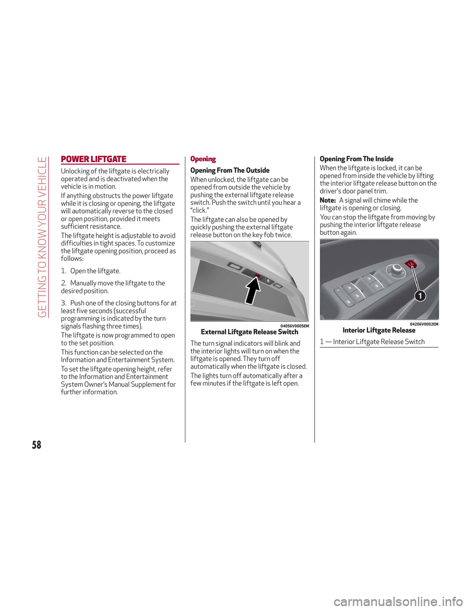
When unlocked, the liftgate can be
opened from outside the vehicle by
pushing the external liftgate release
switch. Push the switch until you hear a
“click.”
The liftgate can also be opened by
quickly pushing the external liftgate
release button on the key fob twice.
The turn signal indicators will blink and
the interior lights will turn on when the
liftgate is opened. They turn off
automatically when the liftgate is closed.
The lights turn off automatically after a
few minutes if the liftgate is left open.Opening From The Inside
When the liftgate is locked, it can be
opened from inside the vehicle by lifting
the interior liftgate release button on the
driver’s door panel trim.
Note:
A signal will chime while the
liftgate is opening or closing.
You can stop the liftgate from moving by
pushing the interior liftgate release
button again.
04056V0005EMExternal Liftgate Release Switch
04206V0002EMInterior Liftgate Release
1 — Interior Liftgate Release Switch
58
GETTING TO KNOW YOUR VEHICLE
Page 61 of 276
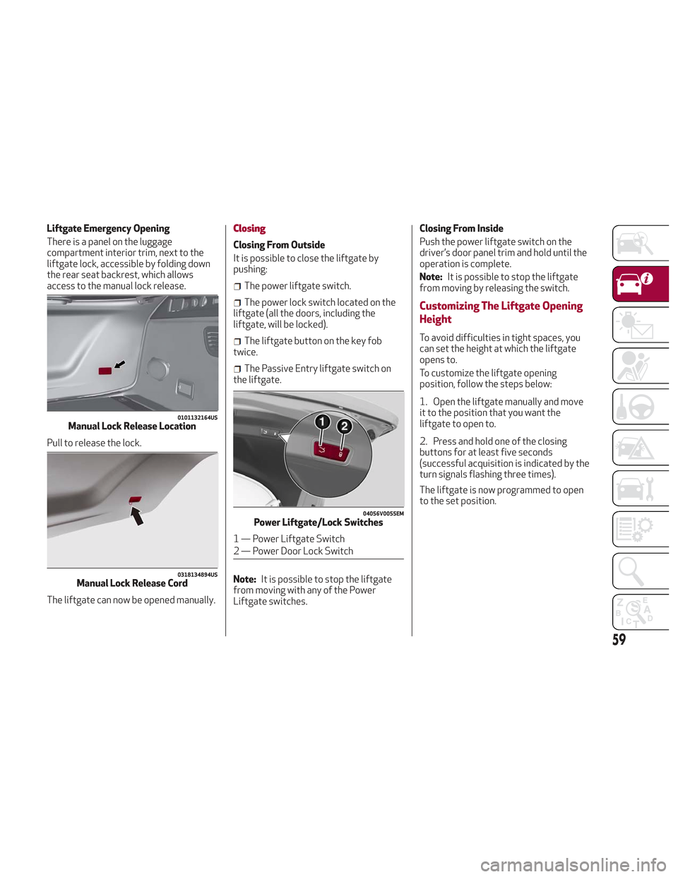
Liftgate Emergency Opening
There is a panel on the luggage
compartment interior trim, next to the
liftgate lock, accessible by folding down
the rear seat backrest, which allows
access to the manual lock release.
Pull to release the lock.
The liftgate can now be opened manually.Closing
Closing From Outside
It is possible to close the liftgate by
pushing:
The power liftgate switch.
The power lock switch located on the
liftgate (all the doors, including the
liftgate, will be locked).
The liftgate button on the key fob
twice.
The Passive Entry liftgate switch on
the liftgate.
Note: It is possible to stop the liftgate
from moving with any of the Power
Liftgate switches. Closing From Inside
Push the power liftgate switch on the
driver’s door panel trim and hold until the
operation is complete.
Note:
It is possible to stop the liftgate
from moving by releasing the switch.
Customizing The Liftgate Opening
Height
To avoid difficulties in tight spaces, you
can set the height at which the liftgate
opens to.
To customize the liftgate opening
position, follow the steps below:
1. Open the liftgate manually and move
it to the position that you want the
liftgate to open to.
2. Press and hold one of the closing
buttons for at least five seconds
(successful acquisition is indicated by the
turn signals flashing three times).
The liftgate is now programmed to open
to the set position.
0101132164USManual Lock Release Location
0318134894USManual Lock Release Cord
04056V0055EMPower Liftgate/Lock Switches
1 — Power Liftgate Switch
2 — Power Door Lock Switch
59
Page 62 of 276

Hands Free Liftgate — If Equipped
To operate the Hands Free Liftgate
System:
1. If the doors are locked, the system
must detect the electronic key near the
liftgate.
2. If the doors are unlocked, the system
does not have to detect the electronic
key near the liftgate.
3. Go to the rear of the vehicle, in the
center and about 3 feet (1 m) from the
liftgate.
4. Move your foot under the bumper,
simulating a kick. When you have
completed this movement, withdraw your
leg. To activate the liftgate, both sensors
must detect your leg.If it is closed, the Hands Free Liftgate
unlocks and opens completely, and with
another movement of the foot, it stops. A
further movement of the foot reverses
the direction and closes the liftgate
completely, if you do not stop it again.
If it is open, with a movement of the foot,
the Hands Free Liftgate closes
completely, and with another movement
of the foot, it stops. If the liftgate is
stopped, another movement of the foot
will reverse the direction and open it
completely.
Note:
To conserve the battery charge,
avoid performing this operation
repeatedly with the engine off.
You can activate/deactivate the Hands
Free Liftgate on the Information and
Entertainment System by pushing the
MENU button to select the Main menu,
and selecting the following items:
1. Settings
2. Doors And Locks
3. Automatic Liftgate Opening Select
them by turning the Rotary Pad and
pushing it.Warning!
Driving with the liftgate open can allow
poisonous exhaust gases into your vehicle.
You and your passengers could be injured by
these fumes. Keep the liftgate closed when
you are operating the vehicle.
If you are required to drive with the
liftgate open, make sure that all windows
are closed, and the climate control blower
switch is set at high speed. Do not use the
recirculation mode.
Warning!
During power operation, personal injury or
cargo damage may occur. Ensure the
liftgate travel path is clear. Make sure the
liftgate is closed and latched before driving
away.
Liftgate Initialization
Note: Automatic operation of the
liftgate must be initialized again in case
of faulty liftgate operation. Proceed as
follows:
1. Close all the doors and the liftgate.
2. Push the lock button on the key fob.
3. Push the unlock button on the key fob.
0101132146USHands Free Liftgate Activation Zone
60
GETTING TO KNOW YOUR VEHICLE
Page 65 of 276

INTERNAL EQUIPMENT
Glove Compartment
To open the glove compartment proceed
as follows:
1. If equipped with a lock, unlock the
glove compartment by placing the
emergency key into the lock on the
handle.
2. Pull the handle to open the glove
compartment.
When the glove compartment is opened,
a light turns on to illuminate the inside of
the compartment.
Note:Do not insert large objects that
prevent the glove compartment from
closing completely. Always make sure
that the glove compartment is
completely closed when driving.
Sun Visors
The sun visors are located at the sides of
the interior rear view mirror. They can be
adjusted forward and sideways.
To direct the visor toward the passenger
side window, detach the visor from the
interior rear view mirror side hook and
turn it towards the side window.
From this position, the sun visor can also
be extended toward the rear of the
vehicle for additional blockage of
sunlight.
Courtesy mirrors with lights are fitted on
the back of the sun visors and can be
used even in poor light conditions.
Note: A rear facing child restraint
system should never be fitted in the front
passenger seat. Always comply with the
instructions on the sun visor. Refer to
"Child Restraints" in "Safety" for more
information.
Homelink
Description
Homelink is a fixed system installed on
the vehicle. It can sync up to three
different devices that activate garage
doors, gates, lighting systems, and home
or office alarm systems.
Programming
Warning!
Vehicle exhaust contains carbon
monoxide, a dangerous gas. Do not run your
vehicle in the garage while programming the
transceiver. Exhaust gas can cause serious
injury or death.
Your motorized door or gate will open and
close while you are programming the
universal transceiver. Do not program the
transceiver if people, pets or other objects
are in the path of the door or gate. Only use
this transceiver with a garage door opener
that has a “stop and reverse” feature as
required by Federal safety standards. This
includes most garage door opener models
manufactured after 1982. Do not use a
garage door opener without these safety
features. Call toll-free 1-800-355-3515 or,
on the Internet at HomeLink.com for safety
information or assistance.
Note: Without starting the engine,
activate the electric park brake and place
the ignition in the ON position.
0403132212USOpening The Glove Compartment
0403132210USRotate Sun Visor Toward Passenger Window
63
Page 78 of 276
in the door jamb stating what the mileage
was before the repair or service. It is a
good idea for you to make a record of the
odometer reading before the
repair/service, so that you can be sure
that it is properly reset, or that the door
jamb sticker is accurate if the odometer
must be reset at zero.
Customer Programmable Settings
Multiple settings can be programmed by
the user using the Information and
Entertainment System. This section
describes only the basic settings:
Units & Language
Time & Date
Cluster
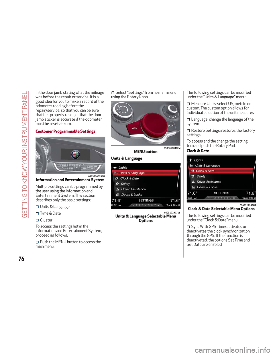
To access the settings list in the
Information and Entertainment System,
proceed as follows:
Push the MENU button to access the
main menu.
Select “Settings” from he main menu
using the Rotary Knob.
Units & Language The following settings can be modified
under the “Units & Language” menu:
Measure Units: select US, metric, or
custom. The custom option allows for
individual selection of the unit measures
Language: change the language of the
system
Restore Settings: restores the factory
settings
To access and the change the setting,
turn and push the Rotary Pad.
Clock & Date
The following settings can be modified
under the “Clock & Date” menu:
Sync With GPS Time: activates or
deactivates the clock synchronization
through the GPS. If the function is
deactivated, the options Set Time and
Set Date are enabled
05036S0015EMInformation and Entertainment System
05036S0040EMMENU button
0503122977USUnits & Language Selectable Menu Options
0503122963USClock & Date Selectable Menu Options
76
GETTING TO KNOW YOUR INSTRUMENT PANEL
Page 79 of 276
Set Time: set the time manually
Time Format: set the time format to
either a 12-hour and a 24-hour clock)
Set Date: set the date manually
Restore Settings: restores the factory
settings
To access and the change the setting,
turn and push the Rotary Pad.
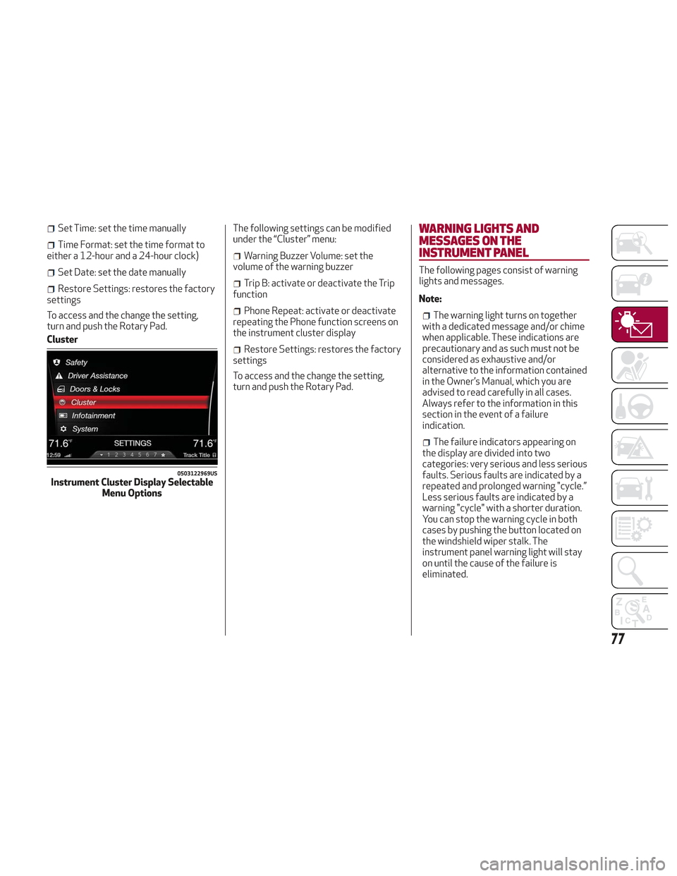
Cluster The following settings can be modified
under the “Cluster” menu:
Warning Buzzer Volume: set the
volume of the warning buzzer
Trip B: activate or deactivate the Trip
function
Phone Repeat: activate or deactivate
repeating the Phone function screens on
the instrument cluster display
Restore Settings: restores the factory
settings
To access and the change the setting,
turn and push the Rotary Pad.
WARNING LIGHTS AND
MESSAGES ON THE
INSTRUMENT PANEL
The following pages consist of warning
lights and messages.
Note:
The warning light turns on together
with a dedicated message and/or chime
when applicable. These indications are
precautionary and as such must not be
considered as exhaustive and/or
alternative to the information contained
in the Owner’s Manual, which you are
advised to read carefully in all cases.
Always refer to the information in this
section in the event of a failure
indication.
The failure indicators appearing on
the display are divided into two
categories: very serious and less serious
faults. Serious faults are indicated by a
repeated and prolonged warning "cycle.”
Less serious faults are indicated by a
warning "cycle" with a shorter duration.
You can stop the warning cycle in both
cases by pushing the button located on
the windshield wiper stalk. The
instrument panel warning light will stay
on until the cause of the failure is
eliminated.
0503122969USInstrument Cluster Display Selectable Menu Options
77
Page 80 of 276

Red Warning Lights
Warning LightWhat It Means What To Do
INSUFFICIENT BRAKE FLUID/ELECTRIC PARK BRAKE
ON
This light monitors various brake functions, including
brake fluid level and parking brake application. If the
brake light turns on it may indicate that the parking brake
is applied, that the brake fluid level is low, or that there is
a problem with the anti-lock brake system reservoir.
If the light remains on when the parking brake has been
disengaged, and the fluid level is at the full mark on the
master cylinder reservoir, it indicates a possible brake
hydraulic system malfunction or that a problem with the
Brake Booster has been detected by the Anti-Lock Brake
System (ABS) / Electronic Stability Control (ESC) system.
In this case, the light will remain on until the condition has
been corrected. If the problem is related to the Brake
Booster, the ABS pump will run when applying the brake,
and a brake pedal pulsation may be felt during each stop.Operation of the Brake Warning Light can be checked by
turning the ignition switch from the OFF position to the
ON/RUN position. The light should illuminate for
approximately four seconds. The light should then turn
off unless the parking brake is applied or a brake fault is
detected. If the light does not illuminate, have the light
inspected by an authorized dealer.
The light also will turn on when the parking brake is
applied with the ignition switch in the ON/RUN position.
This light shows only that the parking brake is applied. It
does not show the degree of brake application.
For low brake fluid level, go to an authorized dealer to
have the system checked as soon as possible.
Release the electric park brake, then check that the
warning light has turned off.
If the warning light stays on, contact an authorized dealer.
ELECTRONIC BRAKING FORCE DISTRIBUTION (EBD)
FAILURE
The simultaneous turning on of the BRAKE (red) and
(amber) warning lights with the engine on indicates
either a failure of the EBD system or that the system is
not available. In this case, the rear wheels may suddenly
lock and the vehicle may swerve when braking abruptly. Drive very carefully to the nearest authorized dealer to
have the system inspected immediately.
78
GETTING TO KNOW YOUR INSTRUMENT PANEL
Page 82 of 276
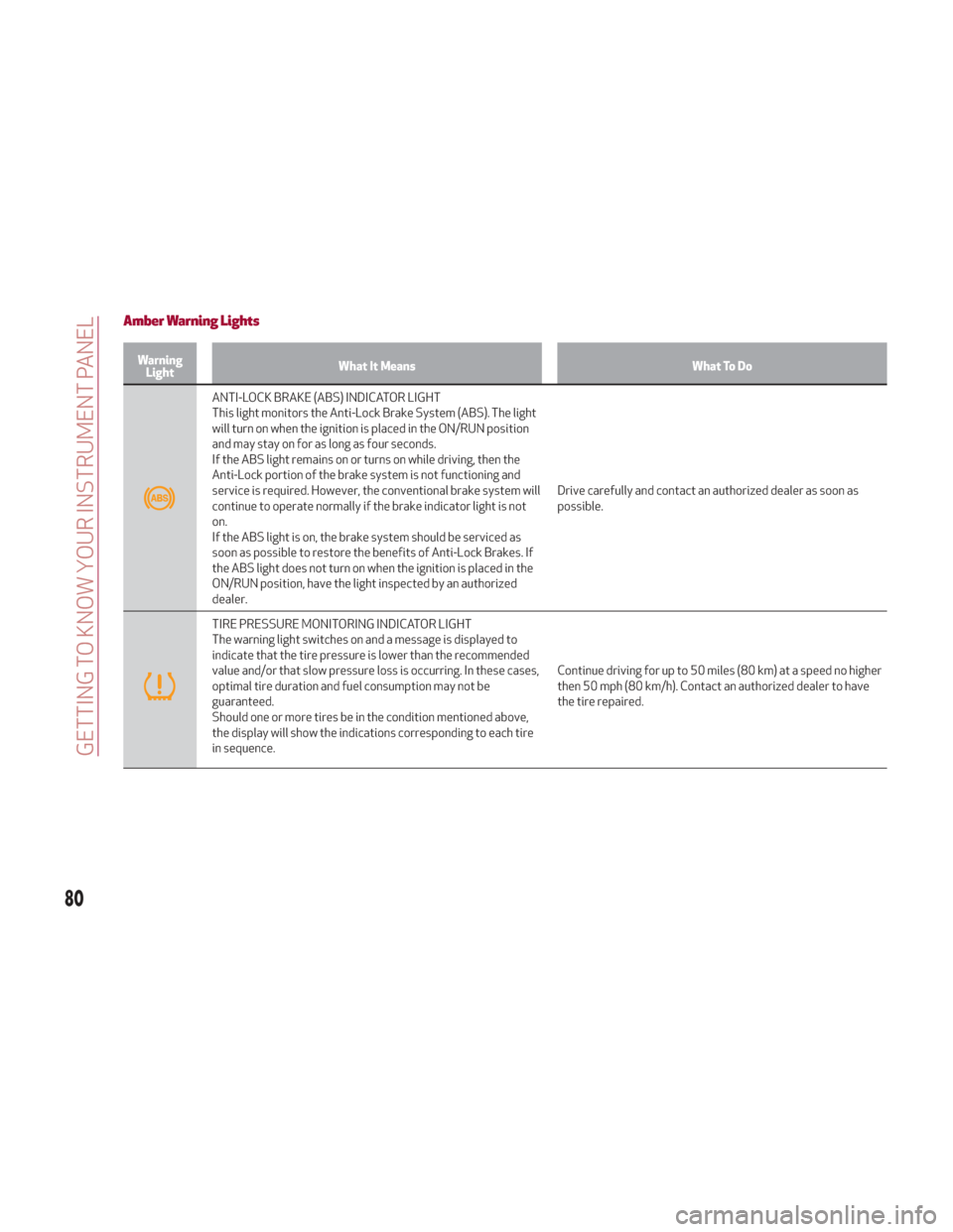
Amber Warning Lights
WarningLight What It Means What To Do
ANTI-LOCK BRAKE (ABS) INDICATOR LIGHT
This light monitors the Anti-Lock Brake System (ABS). The light
will turn on when the ignition is placed in the ON/RUN position
and may stay on for as long as four seconds.
If the ABS light remains on or turns on while driving, then the
Anti-Lock portion of the brake system is not functioning and
service is required. However, the conventional brake system will
continue to operate normally if the brake indicator light is not
on.
If the ABS light is on, the brake system should be serviced as
soon as possible to restore the benefits of Anti-Lock Brakes. If
the ABS light does not turn on when the ignition is placed in the
ON/RUN position, have the light inspected by an authorized
dealer. Drive carefully and contact an authorized dealer as soon as
possible.
TIRE PRESSURE MONITORING INDICATOR LIGHT
The warning light switches on and a message is displayed to
indicate that the tire pressure is lower than the recommended
value and/or that slow pressure loss is occurring. In these cases,
optimal tire duration and fuel consumption may not be
guaranteed.
Should one or more tires be in the condition mentioned above,
the display will show the indications corresponding to each tire
in sequence.
Continue driving for up to 50 miles (80 km) at a speed no higher
then 50 mph (80 km/h). Contact an authorized dealer to have
the tire repaired.
80
GETTING TO KNOW YOUR INSTRUMENT PANEL