2018 Alfa Romeo Stelvio phone
[x] Cancel search: phonePage 3 of 276

DEAR CUSTOMER
Dear Customer,
We would like to congratulate and thank you for choosing Alfa Romeo.
We have written this Owner’s Manual to help you get to know all of the features of your vehicle and use it in the best possible way.
Please take the necessary time to familiarize yourself with all the dynamic features of your vehicle.
Here you will find important information and warnings regarding the use of your vehicle, and how to achieve the best performance
from the technical features of your Alfa Romeo.
You are advised to read through the Owner’s Manual before taking it on the road for the first time. It is important to become familiar
with the controls of your vehicle, especially with sections concerning the brakes, handling, transmission, and vehicle behavior on
different road surfaces.
This Owner’s Manual also provides a description of special features and tips, as well as essential information for the safe driving,
care, and maintenance of your Alfa Romeo over time.
In the provided Warranty Booklet, you will also find a description of the services that Alfa Romeo offers to its customers. The New
Vehicle Limited Warranty will detail the terms and conditions for maintaining its validity.
We are sure that these will help you to get in touch with and appreciate both your new vehicle and the service provided by the people
at Alfa Romeo.
For questions or comments pertaining to your vehicle, please contact the Alfa Romeo Customer Care Center:
P.O. Box 21–8004
Auburn Hills, MI 48321–8004
Phone: 1-844-Alfa-USA (1-844-253-2872)
Page 7 of 276

Radio Transmitters And Mobile Phones
Radio transmitter equipment (vehicle mobile phones, CB radios, amateur radio etc.) cannot be used inside the vehicle unless a
separate antenna is mounted externally.
Transmission and reception of these devices may be affected by the shielding effect of the vehicle body. As far as the use of
approved mobile phones is concerned, follow the usage instructions provided by the mobile phone Manufacturer.
Caution!
The use of these devices inside the passenger compartment (without an external antenna) may cause the electrical systems to malfunction.
This could compromise the safety of the vehicle in addition to constituting a potential hazard for passengers' health.
If mobile phones/laptops/smartphones/tablets are inside the vehicle and/or close to the electronic key, a reduced performance of the Passive
Entry/Keyless Start system may occur may occur.
Page 26 of 276

Caution!
An unlocked vehicle is an invitation. Always
remove the key from the ignition and lock all
of the doors when leaving the vehicle
unattended.
Locking/Unlocking Doors From The
Outside
When locking the doors from the outside
with the doors closed, push the lock
button on the key fob.
The door lock can be activated with all
doors locked and the liftgate open. When
the lock button on the key fob is pushed,
all locks are activated, including the
liftgate if it is open. The liftgate will be
locked when it is closed.
When unlocking the doors from the
outside, push the unlock button on the
key fob.
Locking/Unlocking Doors From The
Outside In An Emergency
If the battery is discharged or the key fob
is inoperable, you can lock or unlock the
doors from the outside by inserting the
blade of the emergency key, found inside
the key fob, into the door handle lock
cylinder and turn the emergency key as
follows.
Lock — Turn the emergency key to the
right (clockwise)
Unlock — Turn the emergency key to
the left (counter clockwise)
Passive Entry
The Passive Entry system can identify
the presence of a key fob near the doors
and liftgate.
The system enables the doors and
liftgate to be locked or unlocked without
pushing any button on the key fob.
The key fob is detected only after the
system recognizes the presence of a
hand on one of the front door handles. If
the detected key fob is valid, the doors
and the liftgate are unlocked (refer to the
Information and Entertainment System
Owner’s Manual Supplement for Passive
Entry Settings).
Note: The key fob may not be able to be
detected by the vehicle keyless-go
system if it is located next to a mobile
phone, laptop, or other electronic device;
these devices may block the key fob’s
wireless signal and prevent the
keyless-go system from starting the
vehicle.
Grasping the handle of the driver's door
unlocks the driver's side door, or all doors
depending on the mode set using the
Information and Entertainment System
(refer to the Information and
Entertainment System Owner’s Manual
Supplement for Passive Entry Settings). Note:
If wearing gloves, or if it has rained
and the door handle is wet, the activation
sensitivity of the Passive Entry function
may be reduced, resulting in a longer
reaction time.
Door Locking
To lock the doors, proceed as follows:
1. Make sure that you have the key fob
and are close to the driver’s or
passenger’s side door handle.
2. Push the Passive Entry door handle
button or the Passive Entry liftgate
button, which is located next to the
external liftgate release button. This will
lock all doors and the liftgate. Door
locking will activate the alarm as well.
0101132144USPassive Entry Door Handle Button
24
GETTING TO KNOW YOUR VEHICLE
Page 70 of 276

Rear Armrest
The rear armrest is foldable and can be
stored in the backrest.
To lower the armrest, pull on the tab
located at the top of the seatback and
fold it downward.
To re-close the armrest, lift it until it is
inserted into the backrest.
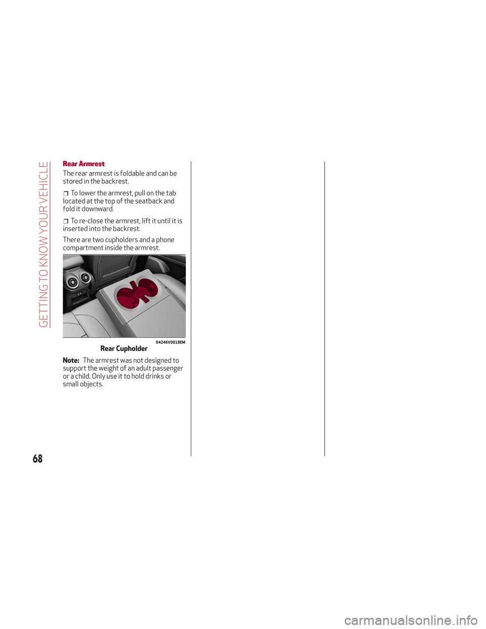
There are two cupholders and a phone
compartment inside the armrest.
Note: The armrest was not designed to
support the weight of an adult passenger
or a child. Only use it to hold drinks or
small objects.
04246V0018EMRear Cupholder
68
GETTING TO KNOW YOUR VEHICLE
Page 75 of 276

Reconfigurable Display Items
1.Headlight Warning Lights
Displays the headlight warning light for
either of the following active modes:
Headlights
Automatic Headlights
2. Gear Selector Information
Displays the following information
controlled by the gear selector function:
P = PARK
R = REVERSE
N = NEUTRAL
D= DRIVE, (automatic forward speed)
AutoStick: + shifting to higher gear in
manual (sequential) driving mode –
shifting to lower gear in sequential
driving mode
3. Forward Collision, Lane Departure,
Cruise Control
Displays operations for the following
modes:
Forward Collision Warning (FCW)
Lane Departure Warning (LDW)
Cruise Control (CC) or Active Cruise
Control (ACC) (if equipped) 4.
Speed Limit Warning Light
Shows information regarding the Speed
Limiter function.
5. Compass
6. Reconfigurable Main Area
Can display the following screens:
Home
Trip A
Trip B (can be activated/deactivated
through the Information and
Entertainment System)
Performance
The screens can be selected, on rotation,
by pushing the MENU selection button on
the windshield wiper stalk.
Depending on the driving mode chosen
using the Alfa DNA Pro (Dynamic, Natural,
Advanced Efficiency and RACE), the
screens can be graphically different. Navigation instructions and call
information can be set and displayed in
the Information and Entertainment
System.
Home
The parameters shown on the display for
the Dynamic, Natural and Advanced
Efficiency modes are:
Time
Outside Temperature
Current Speed (shown if the repeat
modes of the Phone and Navigation
functions are not active)
Range
05036V0002EMMENU Selection Button
05036S0004NAInstrument Cluster Display
73
Page 79 of 276

Set Time: set the time manually
Time Format: set the time format to
either a 12-hour and a 24-hour clock)
Set Date: set the date manually
Restore Settings: restores the factory
settings
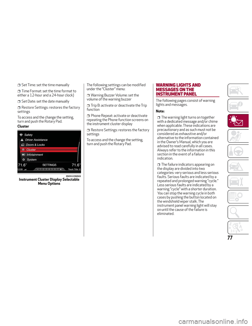
To access and the change the setting,
turn and push the Rotary Pad.
Cluster The following settings can be modified
under the “Cluster” menu:
Warning Buzzer Volume: set the
volume of the warning buzzer
Trip B: activate or deactivate the Trip
function
Phone Repeat: activate or deactivate
repeating the Phone function screens on
the instrument cluster display
Restore Settings: restores the factory
settings
To access and the change the setting,
turn and push the Rotary Pad.
WARNING LIGHTS AND
MESSAGES ON THE
INSTRUMENT PANEL
The following pages consist of warning
lights and messages.
Note:
The warning light turns on together
with a dedicated message and/or chime
when applicable. These indications are
precautionary and as such must not be
considered as exhaustive and/or
alternative to the information contained
in the Owner’s Manual, which you are
advised to read carefully in all cases.
Always refer to the information in this
section in the event of a failure
indication.
The failure indicators appearing on
the display are divided into two
categories: very serious and less serious
faults. Serious faults are indicated by a
repeated and prolonged warning "cycle.”
Less serious faults are indicated by a
warning "cycle" with a shorter duration.
You can stop the warning cycle in both
cases by pushing the button located on
the windshield wiper stalk. The
instrument panel warning light will stay
on until the cause of the failure is
eliminated.
0503122969USInstrument Cluster Display Selectable Menu Options
77
Page 189 of 276

IN CASE OF EMERGENCY
Have a flat tire or a burnt-out bulb?
At times, a problem such as these may
interfere with your driving experience.
The section on emergencies can help you
to deal with critical situations
independently.
In an emergency, we recommend that you
call the phone number found in the
Warranty Book.
You may also consider contacting an
authorized dealer.HAZARD WARNING LIGHTS.....188
BULB REPLACEMENT .........188
FUSES .................. .193
TIRE SERVICE KIT ............198
JUMP STARTING ............201
ENGINE OVERHEATING ........203
TOWING A DISABLED VEHICLE . . .204
TOW EYES ............... .206
ENHANCED ACCIDENT RESPONSE
SYSTEM (EARS) .............207
EVENT DATA RECORDER (EDR) . . .207
187
Page 205 of 276

Cable Disconnection
Once the engine is started, remove the
connection cables in reverse sequence,
as described below:
1. Disconnect the negative (-) end of the
jumper cable from the remote negative (-)
post of the vehicle with the discharged
battery.
2. Disconnect the negative end (-) of the
jumper cable from the negative (-) post of
the booster battery.
3. Disconnect the opposite end of the
positive (+) jumper cable from the
positive (+) post of the booster battery.
4. Disconnect the positive (+) end of the
jumper cable from the positive (+) post of
the vehicle with the discharged battery.
If frequent jump starting is required to
start your vehicle, you should have the
battery and charging system inspected at
an authorized dealer.
Caution!
Accessories plugged into the vehicle power
outlets draw power from the vehicle’s
battery, even when not in use (i.e., cellular
phones, etc.). Eventually, if plugged in long
enough without engine operation, the
vehicle’s battery will discharge sufficiently
to degrade battery life and/or prevent the
engine from starting.
Bump Starting
Never jump start the engine by pushing,
towing or coasting downhill. You cannot
start a vehicle with an automatic
transmission by pushing it.
Caution!
Accessories plugged into the vehicle power
outlets draw power from the vehicle’s
battery, even when not in use (i.e., cellular
phones, etc.). Eventually, if plugged in long
enough without engine operation, the
vehicle’s battery will discharge sufficiently
to degrade battery life and/or prevent the
engine from starting.
ENGINE OVERHEATING
Engine overheating may occur in
situations such as (but not limited to)
extreme environmental temperatures or
frequent engine stops/starts. If the
engine becomes overheated, the Engine
Temperature Warning Light in the
instrument cluster will illuminate along
with a dedicated message. Refer to
"Warning Lights And Messages On The
Instrument Panel" in the "Getting To
Know Your Instrument Panel" for more
information.
In any of the following situations, you can
reduce the potential for overheating by
taking the appropriate action.
On the highways — slow down.
In city traffic — while stopped, place
the transmission in NEUTRAL, but do not
increase engine idle speed.
Note: There are steps that you can take
to slow down an impending overheat
condition:
If your air conditioner (A/C) is on, turn
it off. The A/C system adds heat to the
engine cooling system and turning the
A/C off can help remove this heat.
You can also turn the temperature
control to maximum heat, the mode
control to floor and the blower control to
high. This allows the heater core to act
as a supplement to the radiator and aids
in removing heat from the engine cooling
system.
203