2018 Alfa Romeo Stelvio lock
[x] Cancel search: lockPage 159 of 276

The automatic activation of PARK (P)
when the engine is stopped can also be
deactivated on the Information and
Entertainment system by selecting the
following functions on the main menu:
"Settings", "Driver Assistance" and
"Automatic Parking Brake".
Important Notes
Failure to comply with what is reported
below may damage the transmission:
Shift into PARK (P) mode only with the
vehicle at a standstill.
Select REVERSE (R) mode, or pass
from REVERSE to another mode only
with the vehicle at a standstill and engine
idling.
Do not change between PARK (P),
REVERSE (R), NEUTRAL (N) or DRIVE (D)
modes with engine running at a speed
above idling.
Before activating any transmission
operating mode, fully depress the brake
pedal.
Note: The unexpected movement of the
vehicle can injure the occupants or
people nearby. Do not leave the vehicle
with engine running: before getting out of
the passenger compartment always
engage the electric park brake, select the
PARK (P) mode, stop the engine.
Warning!
It is dangerous to shift out of PARK or
NEUTRAL if the engine speed is higher than
idle speed. If your foot is not firmly pressing
the brake pedal, the vehicle could
accelerate quickly forward or in reverse.
You could lose control of the vehicle and hit
someone or something. Only shift into gear
when the engine is idling normally and your
foot is firmly pressing the brake pedal.
Unintended movement of a vehicle could
injure those in or near the vehicle. As with all
vehicles, you should never exit a vehicle
while the engine is running. Before exiting a
vehicle, always apply the park brake, shift
the transmission into PARK, and turn the
ignition STOP/OFF. When the ignition is in
the STOP/OFF mode, the transmission is
locked in PARK, securing the vehicle against
unwanted movement.
When leaving the vehicle, always make
sure the ignition is in the STOP/OFF mode,
remove the key fob from the vehicle, and
lock the vehicle.
Never leave children alone in a vehicle, or
with access to an unlocked vehicle. Allowing
children to be in a vehicle unattended is
dangerous for a number of reasons. A child
or others could be seriously or fatally
injured. Children should be warned not to
touch the parking brake, brake pedal or the
transmission gear selector.
Do not leave the key fob in or near the
vehicle (or in a location accessible to
children), and do not leave the ignition in the
AVV or ON mode. A child could operate
power windows, other controls, or move the
vehicle.
Caution!
Only engage the gear with engine at idling
while fully depressing the brake pedal. If the
transmission temperature exceeds the
normal operating limits, the transmission
control unit may change the gear
engagement order and reduce the drive
torque. If the transmission overheats, it
could operate incorrectly until it cools down.
When using the vehicle with extremely
low external temperatures, the
transmission operation may change
depending on the engine and transmission
temperature, as well as vehicle speed.
Activation of the torque converter clutch
and of the eighth gear is inhibited until the
transmission oil is correctly warmed up.
Complete operation of the transmission will
be enabled as soon as the fluid temperature
reaches the predefined value.
157
Page 182 of 276

The table below shows the approximate
distances for each area:
AreaDistance From The
Rear Of The Vehicle
Red 0–11.8
inches
(0–30 cm)
Yellow 11.8 inches to 3.3 feet
(30cm–1m)
Green 3.3feetormore(1m
or more)
Messages On The Display
If the liftgate is opened, the camera will
not detect any obstacle behind the
vehicle. The display will show a dedicated
warning message.
Make sure the liftgate is closed by
pushing next to the lock until it clicks.
Important Notes
Ice, snow or mud on the surface of the
camera may reduce its sensitivity. It is
important to keep the camera surface
clean, and free from debris.
When parking, be aware of obstacles
that may be above or below the camera
range.
REFUELING THE VEHICLE
Refueling The Vehicle
Before refueling, make sure that the fuel
type is correct.
Also, stop the engine before refueling.
Note: An inefficient catalytic converter
leads to harmful exhaust emissions, thus
contributing to air pollution.
Caution!
Never introduce leaded fuel to the tank,
even in small amounts in an emergency, as
this would damage the catalytic converter
beyond repair.
Refueling Capacity
To ensure that you fill the tank
completely, top off twice after the first
click of the fuel nozzle.
Further top-off could cause faults in the
fuel feeding system.
Refueling Procedure
The fuel filler door is unlocked when the
central door locking system is unlocked.
It is automatically locked when the
central locking system is applied. Opening The Fuel Filler Door
To refuel proceed as follows:
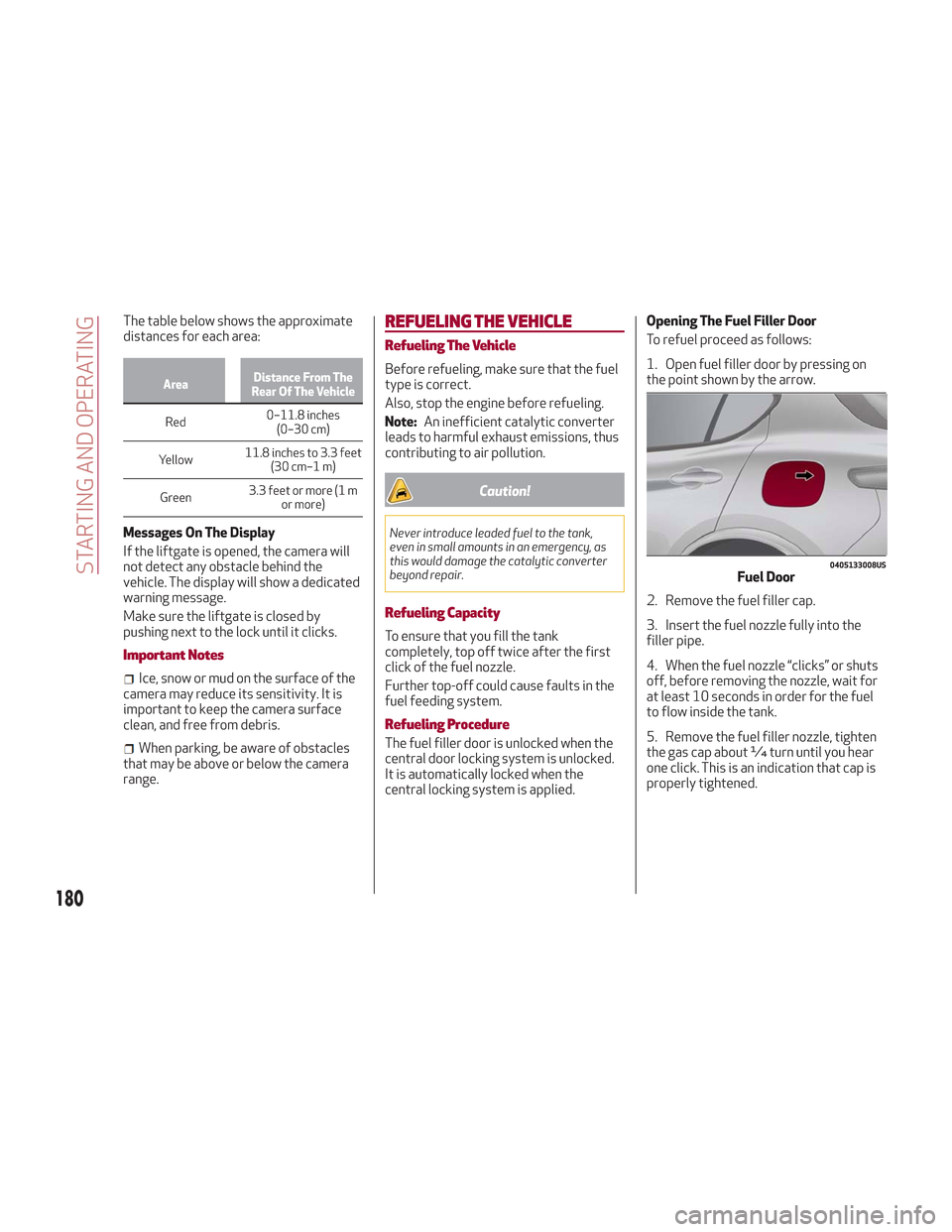
1. Open fuel filler door by pressing on
the point shown by the arrow.
2. Remove the fuel filler cap.
3. Insert the fuel nozzle fully into the
filler pipe.
4. When the fuel nozzle “clicks” or shuts
off, before removing the nozzle, wait for
at least 10 seconds in order for the fuel
to flow inside the tank.
5. Remove the fuel filler nozzle, tighten
the gas cap about ¼ turn until you hear
one click. This is an indication that cap is
properly tightened.
0405133008USFuel Door
180
STARTING AND OPERATING
Page 183 of 276

The label indicates the fuel type
(UNLEADED FUEL = gasoline).
Emergency Fuel Door Opening
In the event of an emergency, the fuel
filler door can be opened from inside the
liftgate.Proceed as follows:
Models Without Compact Spare Tire
1. Open the liftgate and lift up the load
floor.
2. Lift up the cover to reach the
emergency opening cable on the side of
the fuel door.3. Pull the cable to release the fuel door
lock.
4. Open the fuel door by pressing it.
0620132793USFuel Door Label
0604132234USLoad Floor
07226V0041EMCargo Box
1 — Cover
07226V0043EMCargo Box Opened
2 — Release Cable
181
Page 191 of 276

Types Of Bulbs
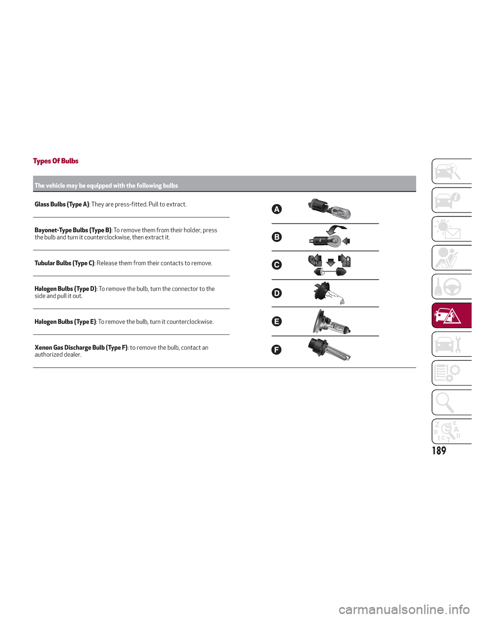
The vehicle may be equipped with the following bulbs
Glass Bulbs (Type A):
They are press-fitted. Pull to extract.
Bayonet-Type Bulbs (Type B) : To remove them from their holder, press
the bulb and turn it counterclockwise, then extract it.
Tubular Bulbs (Type C) : Release them from their contacts to remove.
Halogen Bulbs (Type D) : To remove the bulb, turn the connector to the
side and pull it out.
Halogen Bulbs (Type E) : To remove the bulb, turn it counterclockwise.
Xenon Gas Discharge Bulb (Type F) : to remove the bulb, contact an
authorized dealer.
189
Page 193 of 276

Replacing Exterior Bulbs
Warning!
Only replace bulbs when the engine is off.
Also ensure that the engine is cold, to
prevent the risk of burns.
Front Light Cluster
Direction Indicators
Proceed with the directions below to
change bulbs:
1. Operating inside the engine
compartment, locate the protective
cover.
2. Remove protective cover.3. Turn the bulb/connector assembly
counterclockwise, and then slide it off
the headlight body.
4. Remove the bulb by sliding it off the
bulb holder.
5. Install the new bulb, making sure it is
correctly inserted in the bulb holder.6. Insert the bulb/connector assembly in
the housing on the headlight body and
turn it clockwise, making sure that it is
locked correctly.
7. Install the protective cover.
Front Light Cluster With Main Beam
Xenon Gas Discharge Headlights
To replace the bulbs of the main beam
headlights, contact an authorized dealer.
Caution!
Do not touch the new bulb with your fingers.
Oil contamination will severely shorten bulb
life. If the bulb comes in contact with any oily
surface, clean the bulb with rubbing alcohol.
Replacing Interior Bulbs
Courtesy Mirror Light
To replace the bulbs, proceed as follows:
1. Lift the mirror cover and remove the
lens, using a suitable tool.
08026V0023EMProtective Cover Location
08026V0006EMProtective Cover
08026V0007EMBulb/Connector
191
Page 197 of 276

may result in serious personal injury, fire
and/or property damage.
Before replacing a fuse, make sure that
the ignition is off and that all the other
services are switched off and/or
disengaged.
If the replaced fuse blows again, contact
an authorized dealer.
If a general protection fuse for safety
systems (air bag system, braking system),
power unit systems (engine system,
transmission system) or steering system
blows, contact an authorized dealer.
Fuse Location
The fuses, which can be replaced by the
user, are grouped in two boxes below the
passenger side foot board and inside the
luggage compartment.
Control Unit Under Passenger Side
Footboard
To access the fuses, proceed as follows:
1. Lift the upper end of the footboard on
the passenger side, pulling to release the
two buttons. Release Buttons On Footboard
1 — Footboard
2. Unscrewing the two hooks, remove
the panel pulling downward.
Release Hooks On Footboard
2 — Panel
The fuses are freely accessible on the
control unit.
After replacing the fuse, make sure that
panel and footboard are correctly locked.
Luggage Compartment Fuse Box
To access the fuses, proceed as follows:
1. Lift the luggage compartment cover.
2. Remove the control unit cover.
The fuses are freely accessible on the
control unit.
The number identifying the electrical
component corresponding to each fuse is
shown on the cover.
After replacing a fuse, make sure that
you have closed the cover correctly.
08036V0010EM
08036V0011EM
08036V0014EMControl Unit
195
Page 198 of 276

Control Unit Under Passenger Side Footboard
FUNCTIONFUSEAMPERAGE
Front power window (driver’s side) F3325
Front
power window (passenger side) F3425
Supply for Information and Entertainment system, Climate Control
system, alarm, power door mirror folding, EOBD system, USB port F36
15
Safe Lock device (driver side door unlock – if equipped), doors
unlock, central lock F38
20
Windshield washer pump F4320
Rear left power window F4725
Rear right power window F4825
Heater rear window coil F9415
08036S0013EMPassenger Side Control Unit
196
IN CASE OF EMERGENCY
Page 203 of 276

If the tire is over inflated, reduce the
pressure by pushing the PSI/BAR button
and releasing it when the correct
pressure is reached.
JUMP STARTING
If your vehicle has a discharged battery, it
can be jump started using a set of jumper
cables and a battery in another vehicle, or
by using a portable battery booster pack.
Jump starting can be dangerous if done
improperly, so please follow the
procedures in this section carefully.
Note:When using a portable battery
booster pack, follow the manufacturer's
operating instructions and precautions.
Warning!
Failure to follow this jump-starting
procedure could result in personal injury or
property damage due to battery explosion.
Caution!
Do not use a portable battery booster pack
or any other booster source with a system
voltage greater than 12 Volts or damage to
the battery, starter motor, alternator or
electrical system may occur.
Remote Battery Connection Posts
The remote posts of the battery for jump
starting can be found inside the engine
compartment. The battery itself is
located in the luggage compartment.
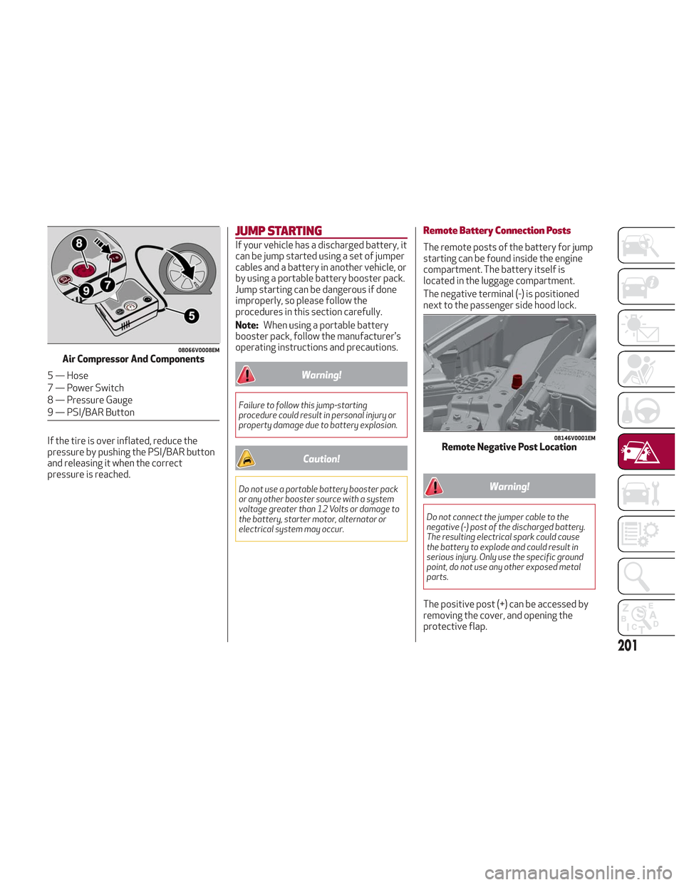
The negative terminal (-) is positioned
next to the passenger side hood lock.
Warning!
Do not connect the jumper cable to the
negative (-) post of the discharged battery.
The resulting electrical spark could cause
the battery to explode and could result in
serious injury. Only use the specific ground
point, do not use any other exposed metal
parts.
The positive post (+) can be accessed by
removing the cover, and opening the
protective flap.
08066V0008EMAir Compressor And Components
5 — Hose
7 — Power Switch
8 — Pressure Gauge
9 — PSI/BAR Button
08146V0001EMRemote Negative Post Location
201