Page 265 of 286

Mounting a wheel
Vehicle preparation
XStop the vehicle as far away as possible from
traffic and on a level, firm and non-slip sur-
face.
XIf your vehicle poses a risk to approaching
traffic, switch on the hazard warning lamps.
XApply the parking brake.
XTurn the front wheels to the straight-ahead
position.
XMove the selector lever of the automatic
transmission to position P.
XSwitch off the engine.
XPassengers should leave the vehicle. Make
sure that the passengers are not endangered
as they do so.
XMake sure that no one is near the danger area
while the wheel is being changed. Anyone
who is not directly assisting in the wheel
change should, for example, stand behind the
barrier.
XPlace the warning triangle or warning lamp at
a suitable distance.
Observe legal requirements.
XSecure the vehicle to prevent it from rolling
away.
iObserve the safety notes on parking in the
section on "Driving and parking"
(
Ypage 127).
XOn level terrain: place chocks or other suit-
able objects under the front and rear of the
wheel that is diagonally opposite the wheel to
be changed.
XOn slight inclines: place chocks or other
suitable objects under the wheels on the front and rear axles opposite the wheel to be
changed.
XTake the vehicle tool kit and the jack from the
footwell on the front-passenger side
(
Ypage 236).
XRemove the spare wheel from the spare wheel
bracket (Ypage 269). Observe the safety
notes in the "Spare wheel" section
(
Ypage 268).
XOn wheels with wheel bolts, remove the hub
caps.
XAssemble the lug wrench extension using the
middle rod and the rod with the largest diam-
eter from the three-piece jack pump lever.
XStarting with the middle rod, slide the lug
wrench extension as far as it will go onto the
lug wrench.
XUsing lug wrench :, loosen the wheel bolts/
wheel nuts on the wheel to be changed by
about one full turn. Do not unscrew the wheel bolts/nuts completely.
Raising the vehicle
GWARNING
If you do not position the jack correctly at the
appropriate jacking point of the vehicle, the
jack could tip over with the vehicle raised.
There is a risk of injury.
Only position the jack at the appropriate jack-
ing point of the vehicle. The base of the jack
must be positioned vertically, directly under
the jacking point of the vehicle.
GWARNING
On uphill and downhill slopes, the jack could
tip over with the vehicle raised. There is a risk
of injury.
Do not change wheels on uphill or downhill
gradients. Notify a qualified specialist work-
shop.
!Only position the jack on the jacking points
intended for this purpose. You could other-
wise damage the vehicle.
Changing wheels263
Wheels and tires
Z
Page 266 of 286

Observe the following when raising the vehicle:
RWhen raising the vehicle, only use the jack
which Mercedes-Benz has specifically
approved for your vehicle.
RThe vehicle's jack is intended only to raise the
vehicle for a short time when changing a
wheel. It is not suited for performing mainte-
nance work under the vehicle.
RAvoid changing the wheel on uphill and down-
hill slopes.
RBefore raising the vehicle, secure it from roll-
ing away by applying the parking brake and
inserting wheel chocks. Never disengage the
parking brake while the vehicle is raised.
RThe jack must be placed on a firm, flat and
non-slip surface. On a loose surface, a large,
load-bearing underlay must be used. On a
slippery surface, a non-slip underlay must be
used, e.g. rubber mats.
RMake sure that the distance between the
underside of the tires and the ground does not
exceed 1.2 in(3 cm).
RNever place your hands or feet under the
raised vehicle.
RNever lie under the raised vehicle.
RNever start the engine when the vehicle is
raised.
RNever open or close a door when the vehicle
is raised.
RMake sure that no persons are present in the
vehicle when the vehicle is raised.
!Only use the jack pump lever middle rod and
the rod with the largest diameter as a lug
wrench extension. Only slide the middle rod
as far as it will go onto the lug wrench. The
rods may otherwise bend and be distorted to
such an extent that they can no longer be
used as a pump lever for the jack.
!Do not place the jack on the leaf spring or
the differential case.
Hydraulic jack
Preparing the hydraulic jack
XInsert the third rod of jack pump lever :into
the lug wrench extension.
Jack pump lever :is assembled.
XClose pressure release screw ;.
XTo do this, use the flattened section on pump
lever:to turn pressure release screw ;
clockwise to the stop.
iDo not turn pressure release screw ;more
than 1 or 2 full turns. Hydraulic fluid could
otherwise escape.
XInsert pump lever :into the recess on the
jack and secure by turning it clockwise.
XPlace the jack vertically beneath the jacking
points described below.
Jacking point, front axle
XPlace the jack under the jacking point in front of the front axle.
XVehicles with all-wheel drive: unscrew jack
spindle =counter-clockwise as far as it will
go.
264Changing wheels
Wheels and tires
Page 267 of 286

Jacking point, rear axle (example: vehicle type
3500)
XPlace the jack under the jacking point in front
of the rear axle.
Jacking point, rear axle")
Jacking point, rear axle (example: vehicle type
2500)
Jacking point, rear axle (example: vehicle type
3500)
XPlace the jack under the jacking point in front
of the rear axle.
Jacking point, rear axle (example: Cab Chassis)Jacking point at the rear axle on chassis ver-
sions
XPlace the jack next to the front leaf spring
support beneath the jacking point.
Removing a wheel
!Do not place the wheel bolts or the wheel
nuts in sand or dirt. The threads of the wheel
bolts and wheel nuts could otherwise be dam-
aged when being tightened.
XUnscrew the wheel bolts or nuts.
XOn front wheels with wheel nuts, remove the
wheel nut cover.
XRemove the wheel.
Installing the adapter
GWARNING
If you tighten the adapter bolts when the vehi-
cle is raised, the jack could tip over. There is a risk of injury.
Make sure that the vehicle is properly pre-
pared for a wheel change. Tighten the adapter
bolts with particular care and attention.
Always observe the instructions and safety
notes on "Changing a wheel" (
Ypage 262).
GWARNING
If you do not tighten the bolts of the adapter to
the specified tightening torque, the adapter
may come loose with the spare wheel. There
is a risk of an accident.
Tighten the bolts of the adapter to the speci-
fied tightening torque. Have the spare wheel
replaced with a complete wheel and an extra- wide tire at a qualified specialist workshop
immediately.
!Vehicles with Super Single tires: if you
install the spare wheel, do not exceed the
maximum speed of 40 mph (60 km/h)and do
not drive further than 65 miles(100 km).
The transmission could otherwise be dam-
aged by the difference in wheel rotation
speeds.
On vehicles with Super Single tires, you must
attach the narrow spare wheel to the rear axle by means of an adapter. The adapter is bolted to
the spare wheel using the adapter bolts for
transportation.
The handling characteristics of your vehicle are
affected when driving with a spare wheel instal-
led. After changing a wheel, drive to the nearest
Changing wheels265
Wheels and tires
Z
Page 268 of 286

specialist workshop and have the spare wheel
replaced with a wheel and tire assembly that has
a Super Single tire.
XClean the wheel and wheel hub contact sur-
faces.
XUnscrew the six adapter bolts on the spare
wheel and remove the adapter.
XTighten the adapter with the six adapter bolts
evenly in a crosswise pattern through the
outer holes on the wheel hub.
XTighten the six adapter bolts on the wheel hub
to a tightening torque of177 lb-ft(240 Nm).
XPush the wheel onto the adapter and attach it.
Mounting a new wheel
GWARNING
Oiled or greased wheel bolts or damaged
wheel bolts/hub threads can cause the wheel bolts to come loose. As a result, you could
lose a wheel while driving. There is a risk of
accident.
Never oil or grease wheel bolts. In the event of
damage to the threads, contact a qualified
specialist workshop immediately. Have the
damaged wheel bolts or hub threads
replaced/renewed. Do not continue driving.
GWARNING
If you tighten the wheel bolts or wheel nuts
when the vehicle is raised, the jack could tip
over. There is a risk of injury.
Only tighten the wheel bolts or wheel nuts
when the vehicle is on the ground.
Always observe the instructions and safety
notes on "Changing a wheel" (
Ypage 262).
Only use wheel bolts or wheel nuts that have
been designed for the wheel and the vehicle. For safety reasons, we recommend that you only
use wheel bolts or wheel nuts which have been
approved for Sprinter vehicles and the respec-
tive wheel.
!For a steel wheel, only use the short wheel
bolts to mount the steel spare wheel. Using
other wheel bolts to mount the steel spare
wheel could damage the brake system.
!On vehicles equipped with a tire pressure
monitor, electronic components are located
in the wheel.
Tire-mounting tools should not be used near
the valve. This could damage the electronic
components.
Only have tires changed at a qualified spe-
cialist workshop.
:Wheel bolt for alloy wheel
;Wheel bolt for steel wheel
XClean the wheel and wheel hub contact sur-
faces.
XVehicles with Super Single tires: first attach
the adapter for the narrow spare wheel to the
wheel hub (
Ypage 265).
Slide the new wheel onto the wheel hub or
onto the adapter for the spare wheel and push
it on.
Slide the new wheel onto the wheel hub and
push it on.
Wheels with centering by wheel bolts:
XVehicles with alloy wheels: take the short
wheel bolts that secure the steel spare wheel
out of the vehicle tool kit.
XScrew in the wheel bolts and tighten them
lightly.
For wheels with wheel nuts:
XFront wheels with wheel nut covers: press the wheel nut covers onto the wheel nuts.
XScrew in the three wheel nuts over the fixing
discs of the wheel nut cover.
XTurn the wheel so that the wheel bolts are in
the middle of the holes.
XScrew on the rest of the wheel nuts.
XSlightly tighten all the wheel nuts.
266Changing wheels
Wheels and tires
Page 269 of 286

Lowering the vehicle
GWARNING
The wheels could work loose if the wheel nuts and bolts are not tightened to the specified
tightening torque. There is a risk of accident.
Have the tightening torque immediately
checked at a qualified specialist workshop
after a wheel is changed.
!Only use the jack pump lever middle rod and
the rod with the largest diameter as a lug
wrench extension. Only slide the middle rod
as far as it will go onto the lug wrench. The
rods may otherwise bend and be distorted to
such an extent that they can no longer be
used as a pump lever for the jack.
!Vehicles with Super Single tires: if you
install the spare wheel, do not exceed the
maximum speed of 40 mph (60 km/h) and do
not drive further than 65 miles(100 km).
The transmission could otherwise be dam-
aged by the difference in wheel rotation
speeds.
Tightening torque pattern
:— B
Wheel bolts or wheel nuts
XUsing the pump lever, slowly turn the lowering
screw on the jack through approximately one
revolution and carefully lower the vehicle
(
Ypage 263).
XPut the jack aside.
XPull the rod with the smallest diameter off the
pump lever.
The shortened pump lever serves as a lug
wrench extension.
XStarting with the middle rod, slide the lug
wrench extension as far as it will go onto the
lug wrench.
XUsing the extended lug wrench, tighten the
wheel bolts evenly in a crosswise pattern in
the sequence indicated ( :toB).
Tighten the wheel bolts to the following tight-
ening torques:
RSteel wheel 177 lb-ft(240 Nm )
RAlloy wheel 133 lb-ft(180 Nm )
Tighten the wheel nuts to a tightening torque
of 133 lb-ft (180 Nm).
XPush the piston on the hydraulic jack in again
and close the pressure release screw.
XVehicles with all-wheel drive: turn the jack
spindle clockwise as far as it will go
(
Ypage 263).
XStow the jack and the rest of the vehicle tools
in the vehicle again.
iYou can now install the hub caps on steel
wheels with wheel bolts. The installing proce-
dure depends on whether the hub cap acts as
a trim that covers the whole wheel, or just
covers the center.
XWheel with hub cap: position the opening for
the tire valve in the hub cap over the tire valve.
XPush the edge of the hub cap with both hands
against the wheel until it clicks into place.
Make sure the hub cap retaining catches
engage on the steel wheel.
XWheel with central hub cap: position the
retaining lugs of the central hub cap over the
wheel bolts.
XHit the center of the hub cap to engage it on
the wheel.
XSecure the faulty wheel in the spare wheel
bracket (Ypage 269).
XVehicles with Super Single tires: transport the
defective rear wheel in the load area. The rear wheel is too large for the spare wheel bracket.
XCheck the tire pressure of the newly mounted
wheel and adjust it if necessary.
Observe the recommended tire pressure
(
Ypage 246).
XRetighten the wheel bolts or wheel nuts to the
specified tightening torque after the vehicle
has been driven for 30 miles (50 km).
When using a wheel or spare wheel with a new or newly painted wheel rim, have the wheel bolts or
nuts retightened again after approximately 600
to 3,000 miles (1,000 to 5,000 km). Observe the
specified tightening torque.
Changing wheels267
Wheels and tires
Z
Page 270 of 286

iVehicles with the tire pressure monitor sys-
tem: all mounted wheels must be equipped
with functioning sensors.
Wheel and tire combination
General notes
!
Retreaded tires are neither tested nor rec-
ommended for Sprinter vehicles, since previ-
ous damage cannot always be detected on
retreaded tires. We can therefore not guar-
antee driving safety. Do not mount used tires
if you have no information about their previ-
ous usage.
The recommended tire pressures can be found:
Ron the Tire and Loading Information placard9
on the B-pillar on the driver's side
Ron the tire pressure table on the B-pillar on the driver's side
The recommended tire pressure can also be
found in the "Tire pressure table" section in this
Operator's Manual (
Ypage 252). The wheel/tire
combination for your vehicle can be found on
the tire pressure table. Further information on
wheel/tire combination can be obtained at any
qualified specialist workshop.
Check tire pressures regularly and only when
the tires are cold. Observe the notes on the rec-
ommended tire pressure (
Ypage 246).
Follow the maintenance recommendations in
the tire manufacturer's warranty book in your
vehicle documents.
Notes on the vehicle equipment – always equip the vehicle:
Rwith tires of the same size across an axle (left
and right)
Rwith the same type of tires on all wheels at a
given time (summer tires, winter tires)
Tires that have been specially designed and
approved for your vehicle are marked with MO
(Mercedes-Benz Original). You can find this
identification on the tires themselves and in the following table.
iNot all wheel/tire combinations can be
installed at the factory in all countries.
Spare wheel
Important safety notes
GWARNING
Wheel and tire dimensions as well as the type of tire can vary between the spare wheel and
the wheel to be replaced. When the spare
wheel is mounted, driving characteristics may be severely affected. There is a risk of an acci-
dent.
In order to reduce risks:
Ryou should therefore adapt your driving
style and drive carefully.
Rnever mount more than one spare wheel
that differs from the wheel to be replaced.
Ronly use a spare wheel that differs from the
wheel to be replaced for a short time.
Rdo not deactivate ESP®.
Rhave a spare wheel that differs from the
wheel that has been changed replaced at
the nearest qualified specialist workshop.
You must observe the correct wheel and
tire dimensions as well as the wheel type.
When using a spare wheel of a different size, do
not exceed the maximum speed of 80 km/h.
General notes
!
Check the spare wheel regularly to see that
it is secure and has the prescribed tire pres-
sure.
The procedure for mounting the spare wheel is
described in "Mounting a wheel" (
Ypage 263).
The following should be checked regularly, par-
ticularly prior to long journeys:
Rthe tire pressure of the spare wheel, which
should then be corrected if necessary
(
Ypage 246).
Rthe fastenings of the spare wheel bracket.
The spare wheel is located in a spare wheel
bracket under the rear of the vehicle.
Replace the tires after 6 years at the latest,
regardless of wear. This also applies to the spare
wheel.
9Only for vehicles with a gross weight of less than 10,000 lbs (4,536 kg).
268Spare wheel
Wheels and tires
Page 271 of 286
 will not func-
tion for this wheel. The spare wheel is not
equipped with a sensor for monitoring tire
pressure.
Removing and i")
iIf you have mounted a spare wheel, the tire
pressure monitor (Ypage 249) will not func-
tion for this wheel. The spare wheel is not
equipped with a sensor for monitoring tire
pressure.
Removing and installing the spare
wheel
Cargo Van/Passenger Van
Bolt covers for the safety catches (example: Cargo
Van)
Removing
XOpen the rear doors.
XPlace a screwdriver into recesses ;and then
pry off covers :.
XUsing the lug wrench from the vehicle tool kit
(Ypage 236), unscrew the now visible bolts
counter-clockwise by approximately 20 turns.
Spare wheel carrier under the vehicle
XSlightly raise spare wheel bracket Aand
unhook left-hand retaining hook =.
XAssemble the pump lever for the jack and
slide it into sleeve?on spare wheel bracket
A.
XRaise spare wheel bracket Awith the pump
lever and unhook right-hand retaining hook
=.
XSlowly lower spare wheel bracket Adown to
the ground.
XLift spare wheel bracket Aslightly and pull
the pump lever out of sleeve ?.
Spare wheel in the spare wheel carrier
XUse the pump lever to lift the spare wheel
beyond the rear edge of the spare wheel car-
rier.
XCarefully remove the spare wheel from spare
wheel bracket A.
The spare wheel is heavy. When the spare
wheel is removed, the center of gravity
changes due to the heavy weight of the wheel.
The spare wheel may slip down or tip over.
Installing
XCarefully place the spare wheel onto spare
wheel bracket A.
The spare wheel is heavy. When you place the
spare wheel onto spare wheel bracket A, the
center of gravity changes due to the weight of
the wheel. The spare wheel may slip down or
tip over.
XSlide the pump lever for the jack into
sleeve ?on spare wheel bracket A.
XRaise spare wheel bracket Awith the pump
lever and attach right-hand retaining hook =.
XSlightly raise spare wheel bracketAand
attach left-hand retaining hook =.
XPull the pump lever out of sleeve ?.
XUsing the lug wrench, tighten the retaining
hook bolts by turning them clockwise.
XReplace and engage covers:.
XClose the rear doors.
Spare wheel269
Wheels and tires
Z
Page 272 of 286

Cab Chassis version
Removing
XLoosen fender nuts=manually and then
remove them.
XLoosen nuts ;as far as the thread end.
XSlightly raise spare wheel bracket ?and
unhook left-hand retaining hook :.
XAssemble the pump lever for the jack and
slide it into the sleeve on the right-hand side
of spare wheel bracket?.
XRaise spare wheel bracket ?with the pump
lever and unhook right-hand retaining
hook :.
XSlowly lower spare wheel bracket ?down to
the ground.
XLift spare wheel bracket ?slightly and pull
the pump lever out of the sleeve.
XUse the pump lever to lift the spare wheel
beyond the rear edge of spare wheel
bracket ?.
XCarefully remove the spare wheel from the
bracket.
The spare wheel is heavy. When the spare
wheel is removed, the center of gravity
changes due to the heavy weight of the wheel.
The spare wheel may slip down or tip over. Installing
XCarefully place the spare wheel onto spare
wheel bracket
?.
The spare wheel is heavy. When you place the
spare wheel onto spare wheel bracket ?, the
center of gravity changes due to the weight of
the wheel. The spare wheel may slip down or
tip over.
XRaise spare wheel bracket ?with the pump
lever and attach right-hand retaining hook :.
XSlightly raise spare wheel bracket?and
attach left-hand retaining hook :.
XPull the pump lever out.
XTighten nuts;.
XPut fender nuts =in place and tighten them.
270Spare wheel
Wheels and tires
 1
1 2
2 3
3 4
4 5
5 6
6 7
7 8
8 9
9 10
10 11
11 12
12 13
13 14
14 15
15 16
16 17
17 18
18 19
19 20
20 21
21 22
22 23
23 24
24 25
25 26
26 27
27 28
28 29
29 30
30 31
31 32
32 33
33 34
34 35
35 36
36 37
37 38
38 39
39 40
40 41
41 42
42 43
43 44
44 45
45 46
46 47
47 48
48 49
49 50
50 51
51 52
52 53
53 54
54 55
55 56
56 57
57 58
58 59
59 60
60 61
61 62
62 63
63 64
64 65
65 66
66 67
67 68
68 69
69 70
70 71
71 72
72 73
73 74
74 75
75 76
76 77
77 78
78 79
79 80
80 81
81 82
82 83
83 84
84 85
85 86
86 87
87 88
88 89
89 90
90 91
91 92
92 93
93 94
94 95
95 96
96 97
97 98
98 99
99 100
100 101
101 102
102 103
103 104
104 105
105 106
106 107
107 108
108 109
109 110
110 111
111 112
112 113
113 114
114 115
115 116
116 117
117 118
118 119
119 120
120 121
121 122
122 123
123 124
124 125
125 126
126 127
127 128
128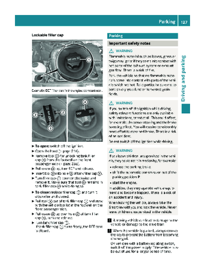 129
129 130
130 131
131 132
132 133
133 134
134 135
135 136
136 137
137 138
138 139
139 140
140 141
141 142
142 143
143 144
144 145
145 146
146 147
147 148
148 149
149 150
150 151
151 152
152 153
153 154
154 155
155 156
156 157
157 158
158 159
159 160
160 161
161 162
162 163
163 164
164 165
165 166
166 167
167 168
168 169
169 170
170 171
171 172
172 173
173 174
174 175
175 176
176 177
177 178
178 179
179 180
180 181
181 182
182 183
183 184
184 185
185 186
186 187
187 188
188 189
189 190
190 191
191 192
192 193
193 194
194 195
195 196
196 197
197 198
198 199
199 200
200 201
201 202
202 203
203 204
204 205
205 206
206 207
207 208
208 209
209 210
210 211
211 212
212 213
213 214
214 215
215 216
216 217
217 218
218 219
219 220
220 221
221 222
222 223
223 224
224 225
225 226
226 227
227 228
228 229
229 230
230 231
231 232
232 233
233 234
234 235
235 236
236 237
237 238
238 239
239 240
240 241
241 242
242 243
243 244
244 245
245 246
246 247
247 248
248 249
249 250
250 251
251 252
252 253
253 254
254 255
255 256
256 257
257 258
258 259
259 260
260 261
261 262
262 263
263 264
264 265
265 266
266 267
267 268
268 269
269 270
270 271
271 272
272 273
273 274
274 275
275 276
276 277
277 278
278 279
279 280
280 281
281 282
282 283
283 284
284 285
285