2017 MERCEDES-BENZ G-Class display
[x] Cancel search: displayPage 146 of 286
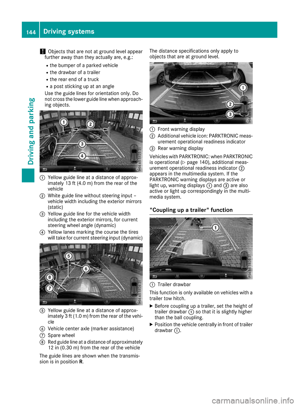
!Objects that are not at ground level appear
further awayt han they actually are, e.g.:
Rthe bumper of aparked vehicle
Rthe drawbarofat railer
Rthe rear end ofatruck
Rap ost sticking up at an angle
Use the guide lines for orientation only. Do
not cross the lower guide line when approach-
ing objects.
:Yellowg uide line at adistance of approx-
imately 13 ft (4.0 m) from the rear of the
vehicle
;White guide line without steering input –
vehicle width including the exterior mirrors
(static)
=Yellowg uide line for the vehicle width
including the exterior mirrors, for current
steering wheel angle (dynamic)
?Yellowl anes marking the course the tires
will take for current steering input (dynamic)
AYellowg uide line at adistance of approx-
imately 3ft(1.0 m) from the rear of the vehi-
cle
BVehicle center axle (marker assistance)
CSpare wheel
DRed guide line at adistance of approximately
12 in (0.30 m)from the rear of the vehicle
The guide lines are shownw hen the transmis-
sion is in position R. The distance specifications only apply to
objects that are at ground level.
:Front warning display
;Additional vehiclei
con: PARKTRONIC meas-
urement operational readiness indicator
=Rea rwarning display
Vehicles with PARKTRONIC: when PARKTRONIC
is operational (
Ypag e140), additiona lmeas-
urement operational readiness indicator ;
appears in the multimedias ystem. If the
PARKTRONIC warning display sare active or
light up, warning displays :and =are also
active or light up correspondinglyint he multi-
medias ystem.
"Coupling up atrailer" function
:Trailer drawbar
This function is only available on vehicles with a
trailer tow hitch.
XBefore coupling up atrailer, set the height of
trailer drawbar :so that it is slightly higher
than the bal lcoupling.
XPosition the vehiclec entrallyinfront of trailer
drawbar :.
144Driving systems
Driving and parking
Page 147 of 286
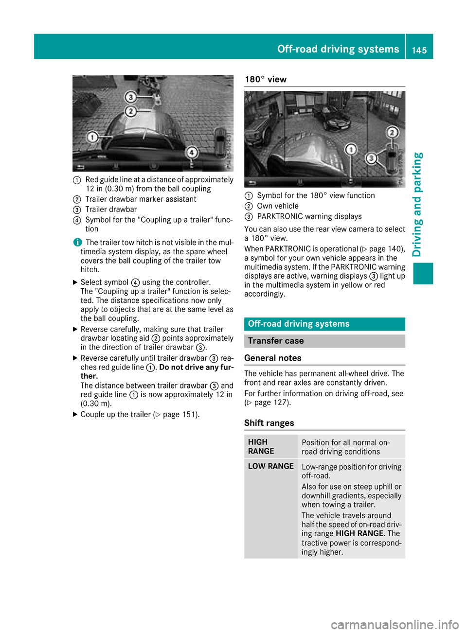
:Red guide lineatadistanceofapproximately
12 in (0.30m)f romt he ball coupling
;Trailer drawbar marker assistant
=Trailer drawbar
?Symbo lfor the "Coupling up atrailer" func-
tion
iThe trailer tow hitch is not visible in the mul-
timedia systemd isplay,asthe spar ewheel
covers the ball coupling of the trailer tow
hitch.
XSelect symbol ?using the controller.
The "Coupling up atrailer" functio niss elec-
ted .The distance specifications now only
appl ytoo bjects thata reat the same level as
the ball coupling.
XReverse carefully, making sure thatt railer
drawbar locating aid ;points approximately
in the direction of trailer drawbar =.
XReverse carefullyuntiltrailer drawbar =rea-
che sred guid eline:. Do no tdriv ea ny fur-
ther.
The distance between trailer drawbar =and
red guid eline : is now approximately 12 in
(0.3 0m).
XCoupl eupthe trailer (Ypage 151).
180° view
:Symbo lfor the 180° vie wfunction
;Ownv ehicle
=PARKTRONICw arning displays
Yo uc an also us ethe rea rviewc amera to select
a1 80° view.
When PARKTRONICi soperational (
Ypage 140),
as ym bolfor your ow nvehicl eappears in the
multimedia system. If the PARKTRONICw arning
displays ar eactive, warning displays =light up
in the multimedia systeminy elloworr ed
accordingly.
Off-roa ddrivin gsystems
Transferc ase
General notes
The vehicl ehaspermanent all-wheel drive. The
front and rea raxles ar econstantl ydriven.
For furtheri nformation on drivin goff-road, see
(
Ypage 127).
Shift ranges
HIGH
RANGEPositio nfor al lnormal on-
roa ddrivin gconditions
LOWR ANGELow-range positio nfor driving
off-road.
Als ofor us eons teep uphill or
downhil lgradients ,especially
when towing atrailer.
The vehicl etravel saround
half the spee dofon-road driv-
ing range HIGH RANGE .The
tractiv epower is correspond-
ingly higher.
Off-roa ddrivin gsystems145
Driving an dparking
Z
Page 148 of 286
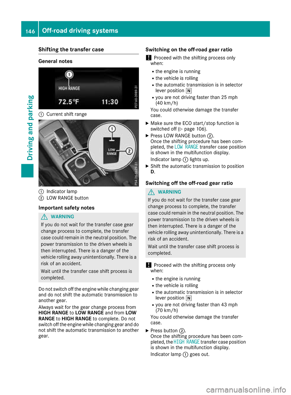
Shifting the transfer case
General notes
:Current shift range
:Indicator lamp
;LOW RANGE button
Important safety notes
GWARNING
If you do not wait for the transfer case gear
change process to complete, the transfer
case could remain in the neutral position. The power transmission to the driven wheels is
then interrupted. There is adanger of the
vehicle rolling away unintentionally. There is a
risk of an accident.
Wait until the transfer case shift process is
completed.
Do not switch off the engine while changing gear
and do not shift the automatic transmission to
another gear.
Always wait for the gear change process from
HIGH RANGE toLOW RANGE and fromLOW
RANGE toHIGH RANGE to complete. Do not
switch off the engine while changing gear and do
not shift the automatic transmission to another
gear.
Switching on the off-road gear ratio
!Proceed with the shifting process only
when:
Rthe engine is running
Rthe vehicle is rolling
Rthe automatic transmission is in selector
lever position i
Ryou are not driving faster than 25 mph
(40 km/h)
You could otherwise damage the transfer
case.
XMake sure the ECO start/stop function is
switched off (Ypage 106).
XPress LOW RANGE button ;.
Once the shifting procedure has been com-
pleted, the LOW RANGE
transfer case position
is shown in the multifunction display.
Indicator lamp :lights up.
XShift the automatic transmission to position
D.
Switching off the off-road gear ratio
GWARNING
If you do not wait for the transfer case gear
change process to complete, the transfer
case could remain in the neutral position. The power transmission to the driven wheels is
then interrupted. There is adanger of the
vehicle rolling away unintentionally. There is a
risk of an accident.
Wait until the transfer case shift process is
completed.
!Proceed with the shifting process only
when:
Rthe engine is running
Rthe vehicle is rolling
Rthe automatic transmission is in selector
lever position i
Ryou are not driving faster than 43 mph
(70 km/h)
You could otherwise damage the transfer
case.
XPress button ;.
Once the shifting procedure has been com-
pleted, the HIGH
RANGEtransfer case position
is shown in the multifunction display.
Indicator lamp :goes out.
146Off-road driving systems
Driving and parking
Page 149 of 286
If the shifting procedure is unsuccessful, the
multifunction display may show the following
messages:
RTC Shift Conditions Not Fulfilled
You have not met one or more shift condi-
tions.
RTC NEUTRAL On
The transfer case has canceled the shifting
procedure and is in positionN.
RTC Shift Canceled
The transfer case has canceled the gear
change process.
XCarry out the gear change process again.
Make sure to meet all conditions for changing
gears.
RTC Malfunction Visit Workshop
There is amalfunction in the transfer case.
XDo not shift the transfer case.
XHave the vehicle checked as soon as possible
ataq ualifieds pecialist workshop.
Shifting to neutral
GWARNING
If you do not wai tfor the transfer case gear
change process to complete, the transfer
case could remain in the neutral position. The powert ransmission to the driven wheelsi s
then interrupted. There is adanger of the
vehicle rolling awa yunintentionally .There is a
risk of an accident.
Waitu ntil the transfer case shift process is
completed.
XTurn the SmartKey to position 2in the ignition
lock.
XApply the parking brake.
XDepress the brake pedal.
XShift the automatic transmission to position
N.
XPress and hold LOW RANGE button ;for
approximately ten seconds.
When the shift procedure is complete, the
multifunction display shows the TC
NEUTRALOnmessagefor five seconds.
If the shifting procedure is unsuccessful, the
multifunction display may show the following
messages (
Ypage 179). If the transfer case is in
Neutral,the SmartKey
is in the ignition lock and you open the driver's
door, the TC NEUTRAL On
messagea ppears in
the multifunction display. If you then release the
parking brake, awarning tone wills ound.
Differential locks
General notes
GWARNING
When the differentiall ocks are engaged,ABS,
4ETS, ESP
®and BAS are deactivated. As a
result, the wheelsc ould lock when braking
and the braking distance is increased.T here is
ar isk of an accident.
Disengage the differentiall ocks immediately
on firm surfaces with good grip.
!In order to avoid damage to the transfer
case, you must operate the vehicle on adyna-
mometer (1-axle dynamometer) only if:
Rthe axle not driven on is jacked up
or
Rthe corresponding propeller shaft is dis-
connected and the transfer case differen-
tial lock is engaged.
Otherwise,t he transfer case can be damaged.
Differential locks improve the traction of the
vehicle.
Your vehicle is equipped with adifferentiall ock
each for:
Rthe transfer case: this controls the balance
betweent he front and rear axles.
Rthe rear axle: this controls the balance
betweenthe wheelsont he rear axle.
Rthe front axle: this controls the balance
betweenthe wheelsont he front axle.
Information on differential gear system
and differential lock
When the vehicle drives around acurve, the
wheelsont he outsideoft he curve must cover a
greater distance. Therefore, the wheelst urn
more rapidly than on the inside. The differential,
ag ear system in the drive train, allows for dif-
fering rotational speedsa nd facilitates corner-
ing.
Off-road driving systems147
Driving and parking
Z
Page 151 of 286
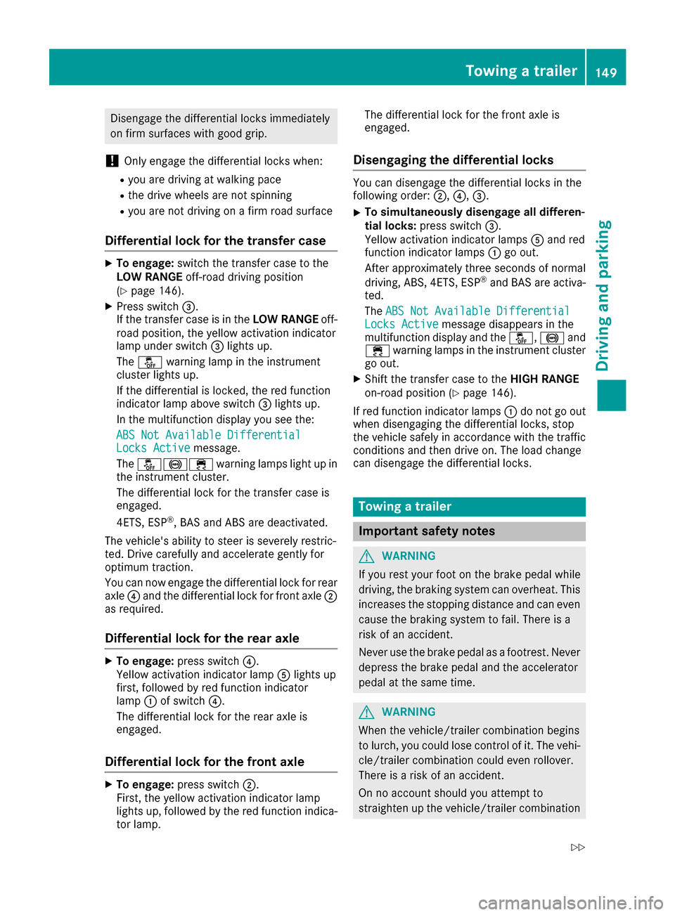
Disengagethe differential locks immediately
on fir msurfaces with good grip.
!Onlye ngagethe differential locks when:
Ryoua redrivin gatw alking pace
Rthe drive wheels ar enot spinning
Ryoua renot drivin gonafirmr oads urface
Differential lock fort he transfercase
XTo engage: switch the transferc asetot he
LO WR ANGE off-roaddrivin gposit ion
(
Ypage 146).
XPress switch =.
If the transferc aseisint heLOWR ANGE off-
roa dposit ion, the yellow activatio nindicator
lamp under switch =lights up.
The å warning lamp in the instrument
cluster lights up.
If the differential is locked ,the red function
indicator lamp above switch =lights up.
In the multifunctio ndisplay yous ee the:
ABS Not Available Differential
Locks Activemessage.
The å!÷ warning lamps light up in
the instrument cluster.
The differential lock for the transferc asei s
engaged.
4ETS, ESP
®,B AS and ABS ar edeactivated.
The vehicle's ability to stee risseverely restric-
ted .Drivec arefull yand accelerate gently for
optimu mtraction.
Yo uc an now engag ethe differential lock for rear
axle ?and the differential lock for front axle ;
as required.
Differential lock fort he rear axle
XTo engage:press switch ?.
Yellow activatio nindicator lamp Alights up
first, followe dbyred functio nindicator
lamp :of switch ?.
The differential lock for the rea raxlei s
engaged.
Differential lock fort he front axle
XTo engage:press switch ;.
First, the yellow activatio nindicator lamp
lights up ,followe dbythe red functio nindica-
tor lamp. The differential lock for the front axl
eis
engaged.
Disengaging the differential locks
Yo uc an disengage the differential locks in the
following order: ;,?,=.
XTo simultaneously disengag eall differen-
tial locks: press switch =.
Yellow activatio nindicator lamps Aand red
functio nindicator lamps :go out.
After approximately threes econdsofnormal
driving, ABS, 4ETS, ESP
®and BAS ar eactiva-
ted.
The ABS Not Available Differential
Locks Activemessage disappears in the
multifunctio ndisplay and the å,!and
÷ warning lamps in the instrument cluster
go out.
XShift the transferc asetot heHIGH RANGE
on-road positio n(Ypage 146).
If red functio nindicator lamps :do not go out
when disengaging the differential locks, stop
the vehicl esafelyina ccordance with the traffic
conditions and thend rive on. The load change
can disengage the differential locks.
Towin gatrailer
Important safety notes
GWARNING
If yo uresty ou rfoo tont he brake peda lwhile
driving, the braking system can overheat. This increases the stopping distance and can even
cause the braking system to fail .There is a
ris kofana ccident.
Never us ethe brake peda lasafootrest. Never
depress the brake peda land the accelerator
peda latthe same time.
GWARNING
When the vehicle/trailer combinatio nbegin s
to lurch, yo ucould lose contro lofit. The vehi-
cle/trailer combinatio ncould eve nrollover.
There is ariskofana ccident.
On no account shoul dyou attempt to
straightenu pthe vehicle/trailer combination
Towin gatrailer149
Driving an dparking
Z
Page 159 of 286

Important safety notes
GWARNING
If you operate information systems and com-
munication equipmen tintegrate dinthevehi-
cle while driving ,you will be distracte dfrom
traffic conditions. You could also lose control
of th evehicle. Ther eisariskofana ccident.
Only operate th eequipmen twhen th etraffic
situation permits. If you are no tsuret hatthis
is possible ,park th evehicl epayin gattention
to traffic condition sand operate th eequip-
men twhen th evehicl eiss tationary.
You must observ ethe legal requirements for th e
country in whic hyou are currentl ydriving when
operating th eon-bo ard computer.
GWARNIN G
If th einstrumen tcluste rhas faile dormal-
functioned, you may no trecognize function
restriction sinsystems relevan ttosafety. The
operating safet yofyour vehicl emay be
impaired .Ther eisar iskofana ccident.
Drive on carefully. Hav ethe vehicl echecked
at aq ualified specialist workshop immedi-
ately.
If th eoperating safet yofyour vehicl eis
impaired ,pull ove rassoonasitiss afetodos o.
Contac taqualified specialist workshop.
The on-board computer only shows message sor
warning sfromc ertai nsystems in th emultifunc-
tion display. You should therefor emakes ure
your vehicl eisoperating safely at all times .
Fo rano verview, see th einstrumen tpanel illus-
tration (
Ypage 32).
Display sand operation
Instrumen tcluster lighting
The brightness control knob is locate donthe
botto mleftoft heinstrumen tcluste r
(
Ypage 32).
XTurn th ebrightness control knob clockwise or
counter-clockwise.
If th eligh tswitch is set to th eÃ, Tor
L position ,the brightness is dependen t
upon th ebrightness of th eambien tlight.
iThe ligh tsensor in th einstrumen tcluste r
automatically control sthe brightness of th e
multifunction display.
In daylight, th edisplays in th einstrumen t
cluste rare no tilluminated.
Speedometer with segments
The segments in th espeedometer indicat e
whic hspee drange is available.
RCruis econtro lactivated (Ypage 131):
The segments ligh tupfromt hestore dspee d
to th eend of th escale.
RDISTRONI CPLUSa ctivated (Ypage 134):
On eort wo segments in th eset spee drange
ligh tup.
RDISTRONI CPLUSd etects avehicl einf ront:
The segments between th espee doft hevehi-
cle in fron tand th estoreds pee dligh tup.
Tachometer
!
Do no tdriveint heoverrevving range, as this
could damag ethe engine.
The red ban dinthetachometer indicates th e
engine's overrevving range.
The fuel suppl yisinterrupted to protect th e
engin ewhen th ered ban disreached.
Outsidet emperatur edisplay
You should pay special attention to road condi-
tion swhen temperatures are aroun dfreezing
point.
Bea rinm indt hatthe outside temperature dis-
play indicates th etem perature measured and
does no trecord th eroad temperature.
The outside temperature display is in th emulti-
function display (
Ypage 159).
Changes in th eoutside temperature are dis-
played after ashort delay.
Display sand operation157
On-boardc omputer and displays
Z
Page 160 of 286
Coolanttemperatur egauge
GWARNING
Opening th ehood when th eengineiso ver-
heated or when there is afireint heengine
compartmen tcoul de xpose you to hot gases
or other servic eproducts. Thereisar isko f
injury.
Let an overheate denginec ooldown before
opening th ehood.Ift here is afireint he
enginec ompartment, keep th ehood closed
and contac tthe fired epartment.
!Ad isplay message is shown if th ecoolant
temperatur eistoohigh.
If th ecoolant temperatur eisover
do no tcontinue driving
.
The engine will otherwise be damaged.
The coolant temperatur egage is in th einstru-
men tcluste ront heright-hands ide (
Ypage 32).
Under normal operatin gconditionsa nd withthe
specifie dcoolant level, th ecoolant temperature
may ris eto
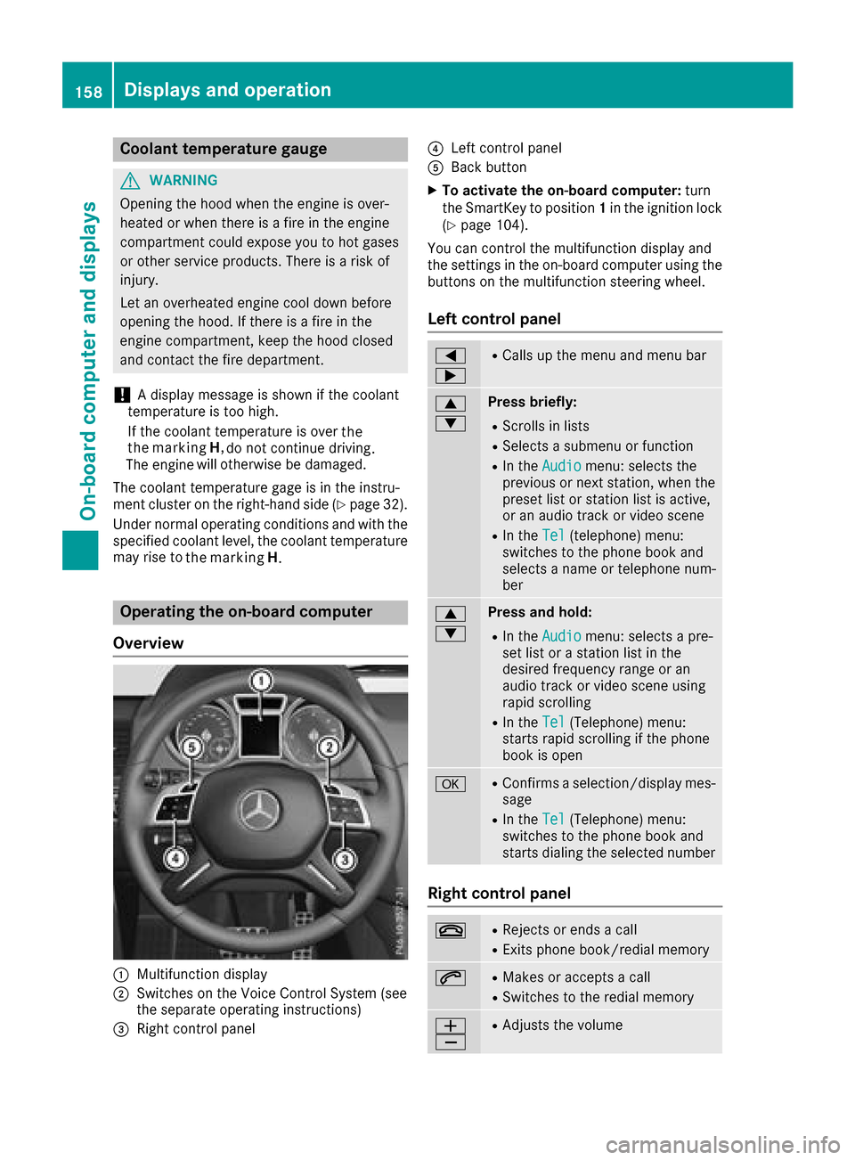
Operatin gthe on-boar dcomputer
Overview
:Multifunction display
;Switches on th eVoiceC ontrol Syste m(see
th es eparate operatin ginstructions)
=Right control panel
?Leftc ontrol panel
ABackbutton
XTo activate th eon-boar dcomputer: turn
th eS ma rtKey to position 1in th eignition lock
(
Ypage 104).
You can control th emultifunction display and
th es ettings in th eon-board computer usingt he
buttons on th emultifunction steering wheel.
Left control panel
=
;RCalls up th emenua nd men ubar
9
:Press briefly:
RScroll sinlists
RSelect sasubmenuorf unction
RIn theAudiomenu: select sthe
previous or next station, when the
preset list or statio nlist is active,
or an audio track or vide oscene
RIn the Tel(telephone )menu:
switches to th ephoneb ook and
selects anam eort elephone num-
ber
9
:Press and hold:
RIn the Audiomenu: selects apre-
set list or astatio nlist in the
desired frequency range or an
audio track or vide oscene using
rapid scrolling
RIn the Tel(Telephone) menu:
start srapid scrolling if th ephone
book is open
aRConfirms aselection/display mes-
sage
RIn the Tel(Telephone) menu:
switches to th ephoneb ook and
start sdialingt heselecte dnumber
Right control panel
~RReject sorendsac all
RExits phoneb ook/redial memory
6RMakes or acceptsac all
RSwitches to theredial memory
W
XRAdjusts th evolume
158Displays and operation
On-boardc omputer and displays
the marking
H
. the
the marking H,
Page 161 of 286
8RMute
?RSwitches on the Voice Control Sys-
tem (see the separate operating
instructions)
Back button
%Press briefly:
RBack
RSwitches off the Voice Control
System
RHides display messages/calls up
the lastTripmenu function used
RExitsthe telephone book/redial
memory
%Press and hold:
RCallsupt he standard display in the
Tripmenu
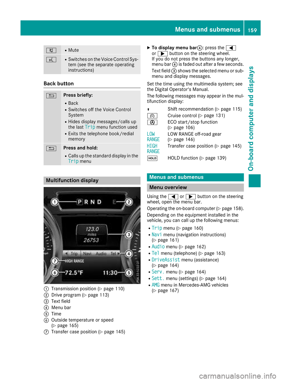
Multifunction display
:Transmission position (Ypage 110)
;Drive program (Ypage 113)
=Text field
?Menu bar
ATime
BOutside temperature or speed
(Ypage 165)
CTransfer case position (Ypage 145)
XTo display menu bar ?:press the =
or ; button on the steering wheel.
If you do not press the buttons any longer,
menu bar ?is faded out after afew seconds.
Text field =shows the selected menu or sub-
menu and display messages.
Set the time using the multimedia system; see
the Digital Operator's Manual.
The following messages may appear in the mul-
tifunction display:
Z Shift recommendation (
Ypage 115)
¯ Cruise control (
Ypage 131)
è ECO start/stop function
(
Ypage 106)
LOW
RANGELOW RANGE off-road gear
(Ypage 146)
HIGH
RANGETransfer case position (Ypage 145)
ë HOLD function (
Ypage 139)
Menus and submenus
Menu overview
Using the =or; button on the steering
wheel, open the menu bar.
Operating the on-board computer (
Ypage 158).
Depending on the equipment installed in the
vehicle, you can call up the following menus:
RTripmenu (Ypage 160)
RNavimenu (navigation instructions)
(Ypage 161)
RAudiomenu (Ypage 162)
RTelmenu (telephone) (Ypage 163)
RDriveAssistmenu (assistance)
(Ypage 164)
RServ.menu (Ypage 164)
RSett.menu (settings) (Ypage 164)
RAMGmenu in Mercedes-AMG vehicles
(Ypage 167)
Menus and submenus159
On-board computer and displays
Z