2017 MERCEDES-BENZ G-Class ECU
[x] Cancel search: ECUPage 154 of 286
Drivingtips
RMaintain agreater distanc efromt hevehicle
in fron ttha nw hen drivin gwithout atrailer .
RAvoid braking abruptly. If possible, brake gen -
tl yatf irst to allow th etrailer to run on .Then,
increase th ebraking forc erapidly.
RThe values given fo rgradient-climbin gcapa-
bilities from astandstill refer to sea level.
Whe ndrivin ginm ountainous areas, note that
th ep owe routput of th eenginea nd,conse -
quently, th evehicle' sgradient-climbin gcapa-
bility, decreases wit hincrea sing altitude.
If th etrailer swings from sid etoside:
XDo no taccelerate.
XDo no tcounter-steer .
XBrakeifn ecessary.
Assemblin gthe ball coupling
GWARNING
The ball couplin gcan be damaged if th enut on
th eb all couplin gistightened usin gthe incor-
rec ttorque. As aresult ,the trailer may
detach .There is ariskofana ccident.
Immediately after installing, hav ethe tighten -
in gt orqu ec hecked ataq ualified specialis t
workshop .
!Mercedes-Ben zrecommends that you only
use ball couplings tested and approved fo r
use on Mercedes-Ben zvehicles .Thish elps to
avoid damage to th evehicle.
Observ ethe manufacturer's installation
instruction sifyou use aball couplin gother
than th eonesupplied .
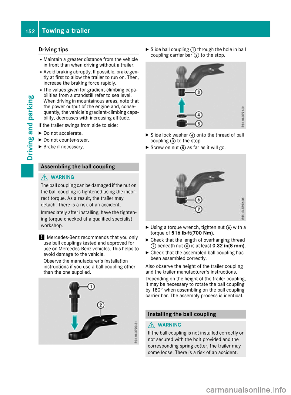
XSlide ball couplin g: through th eholeinb all
couplin gcarrie rbar; to th estop.
XSlide loc kwasher ?onto th ethrea dofb all
couplin g= to th estop.
XScrew on nut Aas far as it will go.
XUsing atorqu ew rench, tighten nut Bwitha
torqu eof516 lb-ft(700 Nm ).
XCheckthatthe lengt hofo verhangin gthrea d
C beneat hnutB is at leas t0.32 in(8 mm) .
XCheckthatthe assembled ball couplin ghas
bee nassembled correctly.
Also observ ethe height of th etrailer couplin g
and th etrailer manufacturer's instructions.
Dependin gontheheight of th etrailer coupling,
it may be necessary to rotate th eball couplin g
by 180° when assemblin gontheball couplin g
carrie rbar.T he assembly process is identical .
Installing theballc oupling
GWARNING
If th eball couplin gisnotinstalled correctl yor
no tsecure dwitht he bolt provided and th e
correspondin gsprin gcotter ,the trailer may
come loose. There is ariskofana ccident.
152Towingatrailer
Driving an dpark ing
Page 155 of 286

Alwaysinstal land secur ethe ball coupling as
described. Before every journey ,ensure that
the ball coupling is secured with the bolt and
the corresponding spring cotter.
GWARNING
If the ball coupling is not correctl yinstalled
and secured ,itcan come loose during the
journey and endanger otherr oadusers.T here
is ar iskofana ccident and injury.
Alway sinstal land secur ethe ball coupling as
described. Before every journey ,ensure that
the ball coupling is secured with the bolt and
the corresponding spring cotter.
XPull protective cap =in the direction of the
arrow,o utof the ball coupling recess.
XInsert the ball coupling horizontally into ball
coupling recess ?in the direction of the
arrow.
XMake sure thatt he holeinballc oupling Ais
in line with the hol einballc oupling recess B.
XSlide boltCinto the hol einthe ball coupling
recess and the ball coupling to the stop.
Towin gatrailer153
Driving an dparking
Z
Page 156 of 286
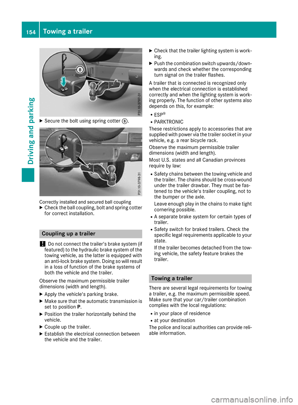
XSecure the boltusing spring cotter D.
Correctlyinstalled and secured ball couplingXCheck the ball coupling, bol tand spring cotter
for correct installation.
Coupling up atrailer
!
Do not connect the trailer's brake system (if
featured) to the hydraulic brake system of the
towing vehicle, as the latter is equipped with
an anti-lock brake system. Doing so will result
in alossoff unction of the brake systems of
both the vehicl eand the trailer.
Observe the maximum permissible trailer
dimensions (width and length).
XAppl ythe vehicle's parking brake.
XMake sure that the automatic transmissio nis
set to position P.
XPosition the traile rhorizontally behind the
vehicle.
XCouple up the trailer.
XEstablish the electrical connection between
the vehicl eand the trailer.
XCheck that the traile rlighting system is work-
ing.
XPush the combination switch upwards/down- wards and check whethert he corresponding
turn signal on the traile rflashes.
At raile rthat is connecte disrecognize donly
when the electrical connection is established
correctly and when the lighting system is work-
ing properly .The function of others ystems also
depends on this ,for example:
RESP®
RPARKTRONIC
These restrictions appl ytoaccessorie sthat are
supplie dwithp ower via the traile rsocketiny our
vehicle, e.g. arearb icycl erack.
Observe the maximum permissible trailer
dimensions (width and length).
MostU .S. state sand al lCanadia nprovinces
require by law
:
RSafety chains between the towing vehicl
eand
the trailer. The chains shoul dbecross-wound
under the traile rdrawbar. Theym ustb efas-
tened to the vehicle's traile rcoupling, not to
the bumpe rorthe axle.
Leave enough play in the chains to make tight
cornering possible.
RAs eparate brake system for certain types of
trailer.
RSafety switch for braked trailers. Check the
specifi clegal requirements applicabl etoyour
state.
If the traile rbecomes detached from the tow-
ing vehicle, the safety feature brakes the
trailer.
Towin gatrailer
There are several legalr equirements for towing
at railer, e.g. the maximum permissible speed.
Make sure that your car/traile rcombination
complies with the local regulations:
Rin your place of residence
Rat your destination
The police and local authorities can provid ereli-
able information.
154Towingat railer
Driving and parking
Page 157 of 286

In order to accumulate driving experience and
accustom yourself to the new handling charac-
teristics, practice the following atalocation
where there is no traffic:
RCornering
RStopping
RBacking up
Before driving, check the following:
RTrailer tow hitch
RSafety switch for braked trailers
RSafety chains
RElectrical connections
RLighting system
RWheelsa nd tires
RLoad-securing measures
Adjust the exterior mirrors to provide an unob-
structed view of the rear section of the trailer.
Trailers with electronically controlled
brakes: pullawaycarefully in the vehicle/trailer
combination, brake manually using the brake
controller and check whether the brakes func-
tion correctly.
Check the load securing measures on aregular
basis.
When towing atrailer, you rvehicle's handling
characteristics willbed ifferent in comparison
with when driving withoutat railer.
The vehicle/trailer combination:
Ris heavier
Ris restricted in its acceleration and gradient-
climbing capability
Rhas an increased braking distance
Ris affected more by strong crosswinds
Rdemands more sensitive steering
Rhas alargert urning radius
Avoid sudden steering movements.
Avoid braking abruptly. If possible, brake gently
at first to allow the trailer to run on. Then,
increase the braking force rapidly.
When overtaking, pay particular attention to the
extended length of you rvehicle/trailer combi-
nation.
Due to the length of the vehicle/trailer combi-
nation, you require additional road space when
overtaking before you can change back to the
originall ane.
If the automatic transmission repeatedly shifts
betweeng ears on uphill or downhill gradients,
shift to alowerg ear. Driving in
alowerg ear and at areduced speed
decreases the risk of engine damage.
Avoid constant braking. Otherwise,t he vehicle
brakes and possibly also the trailerb rakes may
overheat.
When driving downhill, shift to alowerg ear to
utilize the engine's braking effect.
If the coolant temperature increases dramati-
cally whilet he air-conditioning system is
switched on, switch off the air-conditioning sys- tem.
Coolant heat can also be dissipated by opening
the windowsa
nd sw
itching the ventilation
blower and the interior temperature to the high-
est level.
Decoupling atrailer
GWARNING
If you uncoupl eatrailerwith the overrun
brake engaged,y ou could trap you rhand
betweent he vehicle and the trailerd rawbar.
There is arisk of injury.
Do not uncoupl eatrailerift he overrun brake
is engaged.
!Do not disconnect atraile rwith an engaged
overrun brake. Otherwise,y ourv ehicle could
be damaged by the rebounding of the overrun
brake.
XApply the parking brake.
XMake sure that the automatic transmission is
set to position P.
XSecure the vehicle and trailera gainst rolling
away.
XClose all doors, including the rear door.
XRemove the trailerc able.
XRemove the safety chains, if there are any.
XUncouple the trailer.
Permissible trailer and drawbar loads
Weight specifications
The gross trailerw eight is calculated as the
weight of the trailerp lusthe weight of the load
and the trailer'se quipment.
Towingatrailer155
Driving and parking
Z
Page 158 of 286

You will findpermissible trailer loads under
"Technical data" (Ypage 284).
Loading atrailer
RWhen loading the trailer, make sure that nei-
the rthe permissible gross trailer weight nor
the permissible gross vehicle weight are
exceeded. The permissible gross vehicle
weight is indicated on the identification plate
on the B-pillar on the driver's side of the vehi-
cle.
You can findt he maximum permissible values
on the type plates of your vehicle and the
trailer. When calculating how much weight
the vehicle and trailer may carry, pay atten-
tion to the respectiv elowest values.
RThe trailer drawbar load on the ball coupling
must be added to the rear axle load to avoid
exceeding the permissible gross axle weight.
The permissible gross vehicle weight is indi-
cated on the identification plate on the B-pil-
lar on the driver's side of the vehicle.
Mercedes-Ben zrecommends atrailer load
where the trailer drawbar noseweight accounts
for 8% to 15% of the permissible gross trailer
weight.
Additional accessories, passengers and load
reduce the permissible trailer load and nose-
weight that your vehicle can tow.
Checking th evehicle and trailer weight
RHave the towin gvehicle, including the driver,
passengers and load, and completely loaded
trailer weighed on asuitable weighing
machine. This will allow you to ensur ethat the
weightsoft he towingvehicle and trailer com-
ply with the maximum permissible values.
RCheck the gross axle weight ratin gofthe front
and rear axles, the gross weight of the trailer
and trailer drawbar load.
Trailer power supply
!
You can connec taccessories with amaxi-
mum power consumption of 180 Wtothe
permanent power supply.
You must not charge atrailer battery using the
power supply.
The trailer socket of your vehicle is equipped at the factory with apermanent power supply. The permanent power supply is supplied via
trailer socket pin 9.
Aq
ualified specialis tworkshop can provide
more information about installing the trailer
electrics.
Trailer with 7-pin connector
Genera lnotes
Trailersw ith 7-pin connector: you can make a
connection to the 13-pin connector on the ball
couplin gusing an adapter plug or, if necessary,
an adapter cable. Bot hcan be obtained in a
qualified specialis tworkshop.
Installing th eadapt er
!Make sure that there is enough slack in the
cable for cornering so that the cable cannot
becom edetached.
XOpen the socket cover.
XInsert the connector with lug :into
groove ;on the socket and turn it clockwise
to the stop.
XMake the cover engage.
XIf you are using an adapter cable, secur ethe
cable to the trailer with cable ties.
When the socket is connected, PARKTRONIC is
deactivated.
156Towing atrailer
Driving and parking
Page 175 of 286

Display messagesPossible causes/consequences andMSolutions
$(USA
only)
J(C anada
only)
Check Brake Fluid
Level
There is no tenough brak efluidint hebrak efluid reservoir .
In addition ,the $ (USAonly)/ J (Canada only) warning lamp
lights up in th einstrumen tcluste rand aw arning tone sounds.
GWARNIN G
The braking effec tmay be impaired.
There is ariskofana ccident.
XPull overand stop th evehicl esafely as soo naspossible, payin g
attention to roa dand traffic conditions. Do no tcontinue driving
under any circumstances.
XSecur ethe vehicl eagainst rollin gaway (Ypage 120).
XConsult aqualified specialist workshop .
XDo notadd brak efluid .This does no tcorrect them alfunction .
#
CheckBrakePadWear
The brak epads/linings hav ereached their wear limit.
XVisit aqualified specialist workshop .
G
mbrace Inoperative
USA only:on eorm orem ain function softhembrace system are mal-
functioning .
Canad aonly :on eorm orem ain function softheTELE AI Dsystem are
malfunctioning .
XUSA only:hav ethe mbrace system checke dataqualified specialist
workshop .
XCanadaonly :hav ethe Tele AI Dsystem checke dataqualified spe -
cialist workshop .
6
SRSMalfunctionSer‐viceRequired
The restrain tsystem is malfunctioning .The 6 warning lamp also
lights up in th einstrumen tcluster.
GWARNIN G
The air bags or Emergency Tensioning Devices may either be triggered
unintentionally or, in th eevent of an accident, may no tbetriggered .
There is an increased ris kofinjury.
XVisit aqualified specialist workshop .
Fo rfurther information about th erestrain tsystem, see (
Ypage 38).
6
Front Lef tMalfunc‐tionServic eRequiredorFr ontRight MalfunctionServic eRequired
The restrain tsystem has malfunctioned at th efront on th eleftorr ight.
The 6 warning lamp also lights up in th einstrumen tcluster.
GWARNIN G
The air bags or Emergency Tensioning Devices may either be triggered
unintentionally or, in th eevent of an accident, may no tbetriggered .
There is an increased ris kofinjury.
XVisit aqualified specialist workshop .
Display messages173
On-boardc omputer andd isplays
Z
Page 176 of 286

Display messagesPossible causes/consequences andMSolutions
6
RearLeftM alfunc‐tionServic eRequiredorRea rRight MalfunctionServic eRequired
The rear left-han dorright-hand restrain tsystem has malfunctioned.
The 6 warning lamp also lights up in th einstrumen tcluster.
GWARNIN G
The air bags or Emergency Tensioning Devices may either be triggered
unintentionally or, in th eevent of an accident, may no tbetriggered .
There is an increased ris kofinjury.
XVisit aqualified specialist workshop .
6
RearCenterMalfunc‐tionServic eRequired
The rear center restrain tsystem has malfunctioned. The 6warning
lamp also lights up in th einstrumen tcluster.
GWARNIN G
The air bags or Emergency Tensioning Devices may either be triggered
unintentionally or, in th eevent of an accident, may no tbetriggered .
There is an increased ris kofinjury.
XVisit aqualified specialist workshop .
6
LeftSideC urtai nAirbag MalfunctionServic eRequiredorRi ghtSid eCurtai nAirbagMalfunctionServiceRequired
The left-han dorright-hand window curtai nair bag is malfunctioning .
The 6 warning lamp also lights up in th einstrumen tcluster.
GWARNIN G
The lef torright window curtai nair bag may either be triggered unin-
tentionally or, in th eevent of an accident, may no tbetriggered .
There is an increased ris kofinjury.
XVisit aqualified specialist workshop .
FrontPassengerAir‐bag Disabled SeeOperator' sManual
ABabySmart ™compatible child restrain tsystem is installed on th e
front-passenger seat .
The 45indicator lamp also lightsu p.
The front-passenge rair bag is therefore disabled.
Further information on BabySmart™ (
Ypage 53).
174Display messages
On-board computer and displays
Page 177 of 286

Display messagesPossible causes/consequences andMSolutions
FrontPassengerAir‐bag Enable dSeeOperator' sManual
The 45indicator lamp does not remain lit if aspecial Baby-
Smart™-compatible child restraint system has been installed on the
front-passenge rseat.
The BabySmart™ system is malfunctioning.
GWARNING
The front-passenge rfront air bag can be triggeredu nintentionally in
the eventofana ccident.
There is arisk of an accident.
XMake sure there is nothing betwee nthe seat cushio nand the child
seat.
XCheck for correcti nstallation of the child restraint system.
XIf the45indicator lamps do not light up, have the Baby-
Smart™ system checked as soon as possible at aqualified special-
ist workshop.
Do not transport achild on the front-passenge rseat until the air bag
deactivatio nsystem has been repaired.
RadarSensorsDirtySee Operator's Man‐ual
The radar sensor system is malfunctioning.
Possible causes are:
RDirtons ensors
RHeavy rain or snow
RWhen drivingoni nter-urban roads without traffic or infrastructure,
e.g. in desert-lik eareas
At least one drivings ystem is malfunctionin gortemporarily unavail-
able:
RDISTRONIC PLUS
Aw arnin gtonea lso sounds.
Onc ethe cause of the problem is no longer present ,the drivings ys-
tem swill be available again. The display message disappears.
If the display message does not disappear:
XPull over and sto pthe vehicle safely as soon as possible,p aying
attention to road and traffic conditions.
XSecure the vehicle against rollinga way (Ypage 120).
XSwitch off the engine.
XClean all sensors (Ypage 234).
XRestartthe engine.
The display message disappears.
Display messages175
On-board computer and displays
Z