Page 318 of 497

Components damaged in
this wa y may unex‐
pec tedly fail. #
Do not use high-pressure cleaners with
circular jet nozzles toclean theve hicle. #
Have damaged tyres or chassis parts
re placed immediatel y. To
avo id damage to yourvehicle, obser vethefo l‐
lowing when using a high-pressure cleaner:
R Keep theke y at least 3 m away from the
ve hicle. Otherwise the boot lid could open
unintentionall y.
R Maintain a dis tance of at least 30 cm tothe
ve hicle. R
Vehicles with deco rative foil: parts of your
ve hicle are co vered with a decorative foil.
Maintain a dis tance of at least 70 cm
between thefo il-c ove red parts of theve hicle
and the nozzle of the high pressure cleaner.
Mo vethe high-pressure cleaner nozzle
around whilst cleaning.
R Obser vethe information on the cor rect dis‐
ta nce in the equipment manufacturer's oper‐
ating instructions.
R Do not point the nozzle of the high-pressure
cleaner directly at sensitive parts such as
tyres, slits, electrical component parts, bat‐
te ries, light sources and ventilation sl ots. Wa
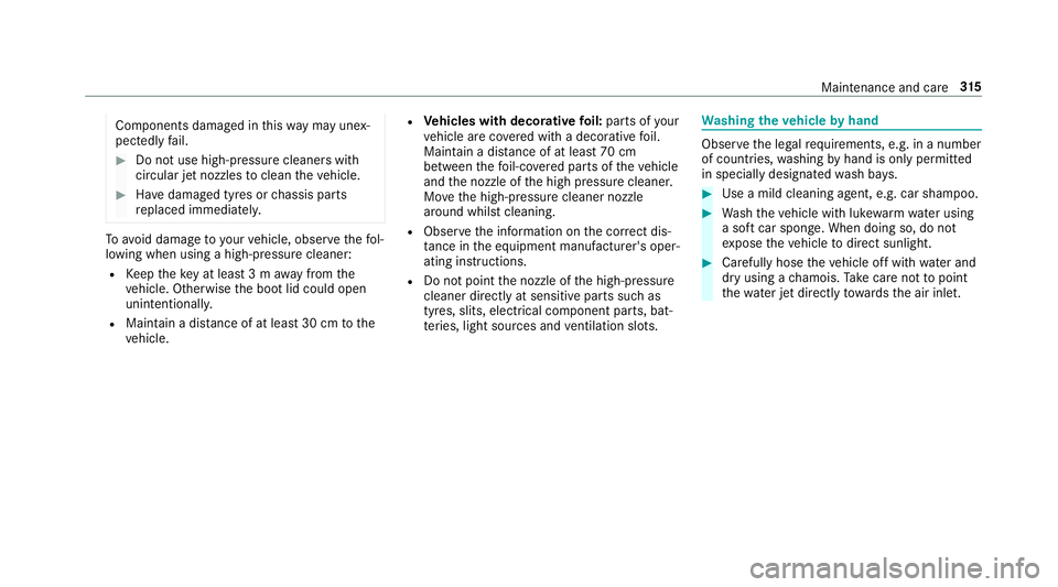
shing theve hicle byhand Obser
vethe legal requ irements, e.g. in a number
of countries, washing byhand is only permitted
in specially designated wash ba ys. #
Use a mild cleaning agent, e.g. car shampoo. #
Washtheve hicle with luk ewarmwate r using
a soft car sponge. When doing so, do not
ex pose theve hicle todirect sunlight. #
Carefully hose theve hicle off with water and
dry using a chamois. Take care not topoint
th ewate r jet directly towa rdsth e air inlet. Maintenance and care
315
Page 326 of 497
Wa
rning triangle Re
moving the warning triangle #
Push bo thsides of warning triangle holder
1 inthe direction of the ar row and open it. #
Remo ve wa rning triangle 2. Setting up
thewa rning triangle #
Fold side reflectors 1upwards toform a tri‐
angle and attach at theto p using press-stud
2. #
Fold legs 3down and out tothe side. Fi
rs t-aid kit (soft sided) The
firs t-aid kit 1is in the boot in the left-hand
stow age net. Breakdown assis
tance 323
Page 329 of 497

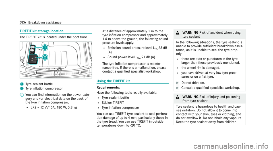
TIREFIT kit
storage location The TIREFIT kit is located under
the boot floor. 1
Tyre sealant bottle
2 Tyre inflation compressor
% You can find information on the po wer cate‐
gory and/or electrical data on the back of
th e tyre inflation compressor.
R LK2 – 12V/15A, 180W, 0.8 kg At
a dis tance of appr oximately 1 m tothe
tyre inflation compressor and appr oximately
1. 6 m abo vethe ground, thefo llowing sound
pressure le vels apply:
R Emission sound pressure le vel L
PA 83 dB
(A)
R Sound po wer le vel L
WA 91
dB (A)
The tyre inflation compressor is mainte‐
nance-free. If there is a malfunction, please
conta ct aqualified specialist workshop. Using
the TIREFIT kit Re
quirements:
Ha ve thefo llowing tools readily available:
R Tyre sealant bottle
R Sticke r TIREFIT
R Tyre inflation compressor
Yo u can use TIREFIT tyre sealant toseal per fora‐
tion dama geof up to4 mm, particular lythose in
th e tyre tread. You can use TIREFIT in outside
te mp eratures down to-20 °C. &
WARNING Risk of accident when using
tyre sealant
In thefo llowing situations, the tyre sealant is
unable toprov ide suf ficient breakdown assis‐
ta nce, as it is unable toseal the tyre prop‐
er ly:
R there are cuts or punctures in the tyre
lar gerth an those pr eviously mentioned.
R the wheel rim is dama ged.
R you ha vedriven at very low tyre pres‐
sures or on a flat tyre. #
Do not drive on. #
Consult a qualified specialist workshop. &
WARNING Risk of inju ryand poisoning
from tyre sealant
Ty re sealant is hazardous tohealth and cau‐
ses ir rita tion. Do not allow it tocome into
contact wi thyour skin, eyes or clo thing, and
do not swallow it. Do not inhale any vapours.
Ke ep the tyre sealant away from children. 326
Breakdown assis tance
Page 342 of 497

As a
result, when transporting vehicles with
th eAd aptive Damping Sy stem PLUS, the
ve hicle/trailer combination may start toskid.
Consequentl y,yo u could lose cont rol of your
ve hicle. #
When transporting, ensure that:
R theve hicle has been loaded onto
th e transpor ter cor rectly
R theve hicle is secured at all four
wheels with suitable tensioning
st ra ps
R the maximum permissible speed of
60 km/h is not exceeded when
transporting *
NO
TEDama getotheve hicle from secur‐
ing it incor rectly #
After loading, theve hicle must be
secured on all four wheels. Otherwise,
th eve hicle could be damaged. #
A minimum dis tance of 20 cm up wards
and 10cm down wards must be kept to
th e transport platform. #
Secure theve hicle on all four wheels af ter
loading.
4MATIC vehicles/ vehicles with automatic
transmission #
Make sure that the front and rear axles come
to rest on the same transpor tation vehicle.
* NO
TEDama getothe driv etra in due to
incor rect positioning #
Do not position theve hicle abo vethe
connection point of the transport vehi‐
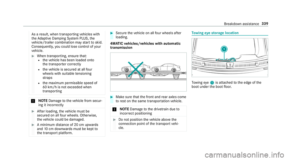
cle. To
wing eyesto rage location To
wing eye1 is attached tothe edge of the
boot under the boot floor. Breakdown assis
tance 339
Page 344 of 497

#
Remo vetheto wing eye. #
Have theve hicle checked at a qualified spe‐
cialist workshop. Electrical fuses
Note
s on electrical fuses &
WARNING Risk of accident and inju ry
due to ov erloaded lines
If yo u manipulate or bridge a faulty fuse or if
yo ure place it with a fuse with a higher
amperage, the electric line could be overloa‐
ded.
This could result in a fire. #
Alw aysre place faulty fuses with speci‐
fi ed new fuses conta iningthe cor rect
amperage. *
NO
TEDama gecaused byincor rect fuses Incor
rect fuses may cause damage toelectri‐
cal components or sy stems. #
Only use Mercedes-Benz appr oved
fuses with the cor rect fuse rating. Blown fuses mu
stbe replaced with fuses of the
same rating, which you can recognise bythe col‐
our and fuse rating. For engine compartment
and boot fuses, only use those fuses mar ked
with an "S". The fuse ratings are li sted in the
fuse assignment diagram.
Fu se assignment diag ram: onthe fuse box in
th e boot (→ page 343).
* NO
TEDama geor malfunctions caused
by moisture Moisture may cause dama
getothe electrical
sy stem or cause it tomalfunction. #
When the fuse box is open, make sure
th at no moisture can enter the fuse
box. #
When closing the fuse box, make sure
th at the seal of the lid is positioned cor‐
re ctly on the fuse box. If
th e newly inser ted fuse also blo ws, ha vethe
cause traced and rectified at a qualified special‐
ist workshop, e.g. a Mercedes-Benz Service
Centre.
Ensure thefo llowing before replacing a fuse:
R The vehicle is secured against rolling away.
R All electrical consumers are switched off.
R The ignition is switched off.
The electrical fuses are located in various fuse
bo xes:
R Fuse box on the driver's side of the engine
compartment (→ page 342)
R Fuse box on the driver's side of the cockpit
(→ page 343)
R Fuse box in the front-passen gerfo ot we ll
(→ page 343)
R Fuse box in the boot on theright-hand side
of theve hicle, when vie wed in the direction
of tr avel (→ page 343) Breakdown assis
tance 341
Page 346 of 497
#
Insert the lid into the brac ket at there ar of
th e fuse box. #
Fold down lid of the fuse box and tighten
scr ews4. #
Insert co ver1 on bo thsides and engage
th e saf ety clips. #
Turn clip 2on co ver1 one quarter-turn to
th eright. #
Close the engine bonn et. Fu
se box on the dashboa rd The fuse box is on
the side of the dashboard
under a co ver. #
Con tact a Mercedes-Benz Service Centre for
fur ther information. Fu
se box in the front-passenger foot we ll Obser
vethe no tes on electrical fuses
(→ page 341). #
Open co ver1 inthe direction of the ar row
and remo veit. Fu
se box in the boot Obser
vethe no tes on electrical fuses
(→ page 341). #
Fold co ver1 down in the direction of the
ar row.
The fuse assignment diagram is in a recess on
th e side of the fuse box. Breakdown assis
tance 343
Page 359 of 497

may se
verely impair the driving characteris‐
tics.
The disk brakes or wheel suspension compo‐
nents may also be damaged. #
Rotate front and rear wheels on lyifthe
wheels and tyres are of the same
dimensions. Inter
changing the front and rear wheels if the
wheels or tyres ha vediffere nt dimensions can
re nder thege neral operating pe rmit in valid.
The wear pat tern s on the front and rear wheels
dif fer:
R Front wheels wear more on the shoulder of
th e tyre
R Rear wheels wear more in the cent reofthe
tyre
On vehicles with the same front and rear wheel
size, you can inter change the wheels every
5,000 to10,000 km, depending on thewe ar.
Ensure the direction of rotation is maintained for
th e wheels. It is imperative
toobser vethe instructions and
saf ety no tes on "Wheel change" when doing so. Note
s onstoring wheels R
Afterre moving wheels, store them in a cool,
dry and preferably dark place.
R Protect the tyres from conta ct withoil,
grease or fuel. Overview of
the ty re-change tool kit Apart from some countr
y-specific variants, vehi‐
cles are not equipped with a tyre-change tool kit.
Fo r more information on which tyre-changing
to ol kit are requ ired and appr ovedfo r per form ing
a wheel change on your vehicle, consult a quali‐
fi ed specialist workshop.
Re quired tyre-change tool kit may include, for
ex ample:
R jack
R chock
R wheel wrench
R centri ng pin %
The jack weighs appr oximately 3.4 kg.
The maximum pa yload of the jack can be
fo und on thest icke r af fixe dto the jac k.
The jack is maintenance-free. If there is a
malfunction, please conta ct aqualified spe‐
cialist workshop.
The tyre-change tool kit is located under the
boot floor. 1
Jack
2 Gloves
3 Wheel wrench
4 Centring pin 356
Wheels and tyres
Page 361 of 497

Aluminium hub cap
#
Toremo ve:position soc ket2 on hub cap
1.
% The soc ket can be found in the tyre-change
to ol kit. #
Position wheel spanner 3on soc ket2. #
Using wheel spanner 3, turn hub cap1
anti-clo ckwise and remo veit. #
Tofit: position hub cap 1and turn until it is
comple tely flush with the wheel. #
Position soc ket2 on hub cap 1. #
Attach wheel spanner 3tosoc ket2 and
tighten the hub cap clockwise.
Specified tightening torq ue: 25 Nm. #
Raise theve hicle (→ page 358). Ra
ising theve hicle when changing a wheel Re
quirements:
R There are no persons in theve hicle.
R The vehicle has been prepared for a wheel
ch ange (→ page 357).
R The hub caps ha vebeen remo ved
( → page 357).
Impor tant no tes on using the jack:
R only use theve hicle-specific jack that has
been tested and appr ovedby Mercedes-Benz
to raise theve hicle.
R the jack is only designed forra ising and hold‐
ing theve hicle for a short time while a wheel
is being changed and not for maintenance
wo rkunder theve hicle. R
the jack must be placed on a firm ,fl at and
non-slip sur face. If necessar y,use a lar ge,
load-bearing, non-slip underla y.
R thefo ot ofthe jack must be positioned verti‐
cally under the jacking point. Ru
les of conduct when theve hicle is raised:
R Never place your hands or feet under the
ve hicle.
R Do not lie under theve hicle.
R Do not start the engine and do not release
th e electric parking brake.
R Do not open or close any doors or the boot
lid. 358
Wheels and tyres