Page 14 of 497
1
Speedom eter →
251
2 ÷ ESP®
→
440
3 #! Turn signal light →
12 9
4 Ð Steering assis tance malfunction →
449
5 Multifunction display →
255
6 ! ABS malfunction →
440
7 ; Engine diagnosis →
451
8 Rev counter →
251
9 % Diesel engine: preglow
A ! Electric parking brake applied (red) →
440
B J Brakes (red) →
440
C # Electrical fault →
451
D · Distance warning →
447
E ? Coolant too hot/cold →
451
F Coolant temp erature display →
251
G J Brakes (yellow) →
440 H
! Electric pa rking brake (yellow) →
440
I 6 Restra int sy stem →
32
J ü Seat belt is not fastened →
446
K j Trailer hit chis not operational or is swivel‐
ling →
449
L T Standing lights →
127
M Fuel le vel display
8 Fuelreser vewith fuel filler flap location
indicator →
451
N K Main beam →
12 9
O L Dipped beam →
127
P R Rear fog light →
12 8
Q AIR BODY CONTROL/DYNAMIC BODY CONTROL
malfunctioning →
447
R h Tyre pressure monitoring sy stem →
454
S å ESP®
OFF →
440 At
aglance – Overview of warning and indicator lamps 11
Page 16 of 497
1
Speedom eter →
251
2 AIR BODY CONTROL/DYNAMIC BODY CONTROL
malfunctioning →
447
3 #! Turn signal light →
12 9
4 Multifunction display →
255
5 Rev counter →
251
6 å ESP®
OFF →
440
÷ ESP®
→
440
7 K Main beam →
12 9
L Dipped beam →
127
T Standing lights →
127
8 ? Coolant too hot/cold →
451
9 Coolant temp erature display →
251
A · Distance warning →
447
B Ð Steering assis tance malfunction →
449
C # Electrical fault →
451 D
J Brakes (red) →
440
E ü Seat belt is not fastened →
446
F Fuel le vel display
G 8 Fuelreser vewith fuel filler flap location
indicator →
451
H R Rear fog light →
12 8
I 6 Restra int sy stem →
32
J % Diesel engine: preglow
K ; Engine diagnosis →
451
L J Brakes (yellow) →
440
M ! Electric pa rking brake applied (red) →
440
N h Tyre pressure monitoring sy stem →
454
O ! ABS malfunction →
440
P ! Electric pa rking brake (yellow) →
440
Q j Trailer hit chis not operational or is swivel‐
ling →
449 At
aglance – Overview of warning and indicator lamps 13
Page 78 of 497
Problem
Possible causes/consequences and M
MSolutions
R The key is faulty. #
Activate KEYLESS-GO . #
Check the battery using the battery check lamp and replace if necessary . #
Use the emer gency keyto lock or unlock theve hicle . #
Have theve hicle and keych ecked at a qualified specialist workshop. Ac
tivating/deactivating the automatic lo ck‐
ing feature The
vehicle is loc ked automatically when the
ignition is switched on and the wheels are turn‐
ing fast erthan walking pace. #
Toactivate: press and hold button 2for
appr oximately five seconds until an acoustic
signal sounds. #
Todeactivate: press and hold button 1for
appr oximately five seconds until an acoustic
signal sounds.
There is a danger of being loc ked out if the func‐
tion is activated:
R While theve hicle is being tow star ted/
pushed.
R On a roller dynamome ter. Opening and closing
75
Page 132 of 497

g
Driver's seat and front passenger seat occu‐
pied
1 Driver's seat, front passenger seat and rear
seats occupied
2 Driver's seat, front passenger seat and rear
seats occupied, boot laden
3 Driver's seat and front passenger seat occu‐
pied and maximum permissible rear axle
load utilised #
Turn the headlamp range adjus terto the
position which cor responds tothe load con‐
dition of your vehicle. Operating
the lights combination switch 1
Main beam
2 Turn signal light, right 3
Headlamp flasher
4 Turn signal light, left #
Use the combination switch toactivate the
function in question.
Main beam #
Toswitch on: turnthe light switch tothe
L orà position. #
Press the combination switch be yond the
pressure point in the direction of ar row1.
When the main beam is activated, the indica‐
to r lamp for dipped beam Lis deactiva‐
te d and replaced bythe indicator lamp for
th e main beam K. #
Toswitch off: movethe combination switch
back toits starting position.
Headla mpflasher: #
Pull the combination switch in the direction
of ar row3. Light and sight
12 9
Page 133 of 497

Tu
rn signal light #
Toindicate briefl y:press the combination
switch briefly up tothe pressure point in the
direction of ar row2or4.
The cor responding turn signal light flashes
th re e times. #
Toindicate permanentl y:press the combi‐
nation switch be yond the pressure point in
th e direction of ar row2or4. Ac
tivating/deactivating the hazard warning
light #
Press the 1 button.
The hazard warning lamps switch on automati‐
cally if:
R The airbag has been deplo yed.
R The vehicle brakes sharply from a speed of
more than 70 km/h toast andstill. The hazard
warning lamps switch off automati‐
cally when theve hicle reaches a speed exceed‐
ing 10km/h following maximum full-s top brak‐
ing. Ad
aptive functions, MULTIBEAM LED Fu
nction of the Intelligent Light Sy stem
The MULTIBEAM LED headlamps adapt tothe
driving and weather situation and pr ovide exten‐
ded functions for impr oving the illumination of
th ero ad.
The sy stem comprises thefo llowing functions:
R Active headla mps function (→ page131)
R Cor nering light (→ page 131)
R Motorw ay mode (→ page131)
R Enhanced fog light function (→ page132)
R Adversewe ather light (→ page132)
R City lighting ( →page 132)
The sy stem is only active when it is dar k.13 0
Light and sight
Page 140 of 497
Changing bulbs (only
forve hicles with halo‐
ge n headla mps) Note
s onchanging bulbs &
WARNING Risk of bu rns from hot com‐
ponent parts whilst replacing a bulb
Bulbs, lamps and plugs can become very hot
during operation.
When replacing a bulb, you could burn your‐
self on these component parts. #
Allow the component parts tocool
down before replacing the bulb. R
Do not use a bulb if it has been dropped or if
itsglass has been sc ratched. The bulb may
ot herwise explode.
R Do not touch theglass bulb with your bare
hands.
R Protect bulbs from moisture and do not allow
bulbs tocome into contact wi thliquids. Overview of bulb types
The
following bulbs can be replaced. Halogen headlamps
1 Turn signal light: PY 21 W
2 Main beam: H7 55 W
3 Dipped beam: H7 55 W Ta
il lamps
1 Turn signal light: PY 21 W
2 Reversing light: W 16 W Light and sight
137
Page 141 of 497

Changing
the front bulbs (vehicles with halo‐
ge n headla mps) Fi
tting/ removing the co ver on the front
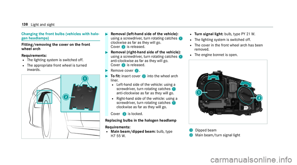
wheel ar ch
Re quirements:
R The lighting sy stem is switched off.
R The appropriate front wheel is turned
in wa rds. #
Remo val (left-hand side of theve hicle):
using a scr ewdriver, turn rotating catches 1
clo ckwise as far as they will go.
Co ver2 isreleased. #
Remo val (right-hand side of theve hicle):
using a scr ewdriver, turn rotating catches 1
anti-clo ckwise as far as they will go.
Co ver2 isreleased. #
Remo vecover2. #
Tofit: inse rtco ver2 into the wheel ar ch
liner.
R Left-hand side of theve hicle: using a
scr ewdriver, turn rotating catches 1
anti-clo ckwise as far as they will go.
R Right-hand side of theve hicle: using a
scr ewdriver, turn rotating catches 1
clo ckwise as far as they will go.
Co ver2 is loc ked.
Re placing bulbs in the halo gen headla mp
Requ irements:
R Main beam/dipped beam: bulb, type
H7 55 W. R
Turn signal light: bulb, type PY 21W.
R The lighting sy stem is switched off.
R The co ver in the front wheel ar chhas been
re mo ved.
R The engine bonn etis open. 1
Dipped beam
2 Main beam/turn signal light 13 8
Light and sight
Page 142 of 497

#
Turn there leva nt housing co ver anti-clock‐
wise and remo veit. #
Main beam/dipped beam: turnthe soc ket
anti-clockwise and remo veit. #
Turn signal light: turnthe soc ket anti-clo ck‐
wise, unlock and remo veit. #
Pull the bulb out of the soc ket. #
Inse rtthe new bulb into the soc ket so that
th e entire base of the bulb is resting on the
bottom of the soc ket. #
Inse rtsoc ket and turn it clo ckwise. #
Press on the housing co ver and turn it clock‐
wise. #
Replace the co ver in the front wheel ar ch. Changing
there ar bulbs (vehicles with halo‐
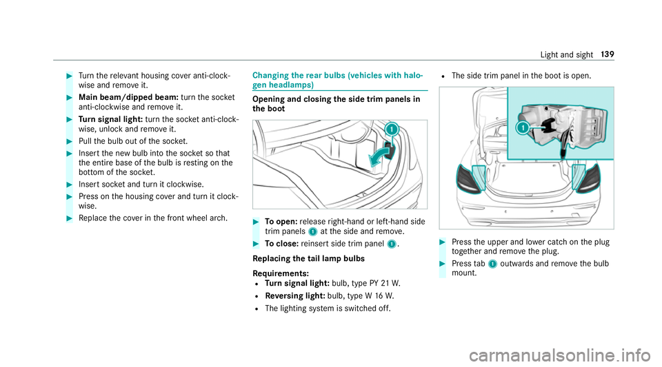
ge n headla mps) Opening and closing
the side trim panels in
th e boot #
Toopen: release right-hand or left-hand side
trim panels 1atthe side and remo ve. #
Toclose: reinse rtside trim panel 1.
Re placing the tail lamp bulbs
Re quirements:
R Turn signal light: bulb, type PY 21W.
R Reversing light: bulb, type W 16W.
R The lighting sy stem is switched off. R
The side trim panel in the boot is open. #
Press the upper and lo wer catch on the plug
to ge ther and remo vethe plug. #
Press tab1 outwards and remo vethe bulb
mount. Light and sight
13 9