Page 97 of 216

45)
The vehicle can be equipped with an
electronically controlled manual
gearbox known as Dualogic which
allows two operating modes: MANUAL
and")
DUALOGIC
GEARBOX
(for versions/markets, where provided)
45)
The vehicle can be equipped with an
electronically controlled manual
gearbox known as Dualogic which
allows two operating modes: MANUAL
and AUTO.
GEAR LEVER
The gear lever A fig. 79, located on the
dashboard, is floating multistable type,
i.e. it has three stable positions and
three unstable positions.
The three stable positions correspond
to neutral (N), reverse (R) and the
central position located between the
unstable positions (+) and (-).The unstable positions, in other words
those that are abandoned as soon
as the lever is released, are the
positions for requesting a higher gear
(+), requesting a lower gear (–) and
requesting automatic operating mode
(A/M).
IMPORTANT With the engine started,
any error between the lever position
and the gear actually engaged is
signalled by a buzzer until consistency
is restored.
MANUAL MODE
Proceed as follows:
press the brake pedal and start the
engine;
if AUTO appears on the display,
move the lever A fig. 79 to A/M to
select MANUAL mode;
push gear lever A towards (+) to
engage first gear (if starting from N or
R, simply place the lever in the middle
position) or R to engage reverse;
release the brake pedal and press
the accelerator pedal;
in driving conditions, push lever A of
the gearbox towards (+) to engage
the next gear up or towards (–) to
engage the next gear down.AUTOMATIC MODE
Proceed as follows:
press the brake pedal;
start the engine;
if AUTO does not appear on the
display, move the gear lever A fig. 79 to
A/M to select AUTOMATIC mode;
push the gear lever towards (+) to
engage 1st gear (if starting from N or R,
simply place the lever in the middle
position) or R to engage reverse;
release the brake pedal and press
the accelerator pedal: the gear most
suited to the vehicle speed will be
engaged.
AUTO-ECO OPERATION
To activate the function press the ECO
button fig. 80 on the central tunnel.
The ECO function can be only activated
only with automatic mode active.
79F1D0107
80F1D0108
95
Page 98 of 216

With the ECO function active, the
system will select the most suitable
gear depending on the vehicle speed,
engine rpm and intensity with which the
accelerator pedal is pressed, with the
aim of limiting fuel consumption.
“Kick Down” FUNCTION
(for versions/markets, where provided)
If necessary (e.g. when overtaking),
the system downshifts one or more
gears when the accelerator pedal
is depressed beyond the point where it
becomes stiff (and if the rpm allow it)
in order to provide suitable power and
torque for the acceleration requested
by the driver.
IMPORTANT The use of the “Kick
Down” function is recommended only
when overtaking or accelerating quickly,
in order not to increase fuel
consumption.
WARNING
45)Avoid keeping your hand on this lever
except during gear change or AUTO/
MANUAL mode requests.
MODE SELECTOR
(Panda Cross versions)
This device allows, using the ring nut of
the knob fig. 81 (on the central tunnel),
three vehicle response modes to be
selected according to driving style and
road conditions:
1 = AUTO mode;
2 = OFF ROAD mode;
3 = HDC function.
The ring nut is monostable type. In
other words, it always remains in a
central position. The selected driving
mode is indicated by the corresponding
LED switching on the knob and by an
indication on the display."AUTO" MODE
It is a driving mode aimed at comfort
and safety in normal grip and driving
conditions.
"OFF ROAD" MODE
It is a driving mode aimed at setting off
in poor grip conditions on low-grip
road surfaces (e.g. snow, ice, mid, etc.).
Engagement
Rotate the ring nut fig. 81 to the right
and hold in this position for half a
second, until the corresponding LED
lights up and “Off Road” mode
activation indicator appears on the
display with a dedicated message.
When the "Off Road" mode is activated,
the presetting for ELD system
intervention activates automatically.
IMPORTANT When the "Off Road"
mode is activated, the Stop/Start
system is temporarily disabled.
Temporary deactivation of the system
switches on the corresponding LED on
the trim (located on the central
dashboard). To activate the Stop/Start
function, with "Off Road" mode on,
press the
button on the dashboard
trim. However, when the "Off Road"
mode is deactivated, the Stop/Start
system is enabled again.
81F1D0116
96
STARTING AND DRIVING
Page 99 of 216

IMPORTANT When the "Off Road"
mode is activated, the City Brake
Control system is temporarily
deactivated. Temporarily deactivation of
the system results in the switching on
of the
warning light on the
instrument panel. When the "Off Road"
mode is deactivated, the City Brake
Control system is enabled again.
Disengagement
To deactivate the "Off Road" mode and
return to the "Auto" mode, rotate the
ring nut to the left and hold in this
position for half a second. In this case,
the LED corresponding to “Auto” mode
will light up and the “Off Road” mode
deactivation indication will appear
on the display.
IMPORTANT If “Off Road” or “Auto”
mode was active when the engine was
stopped, the next time it is started
the mode that was selected is
reactivated.
"HDC" FUNCTION
This driving function permits a constant
vehicle speed to be maintained
downhill.Engagement/Disengagement
For engaging/disengaging the HDC
function refer to the "Active safety
systems" paragraph in the "Safety"
chapter.
FAILURE OF THE MODE
SELECTOR SYSTEM
IMPORTANT In the event of system
failure or a fault with knob, no driving
modes can be selected. The display will
show a dedicated message.
IMPORTANT In this case it is not
advisable trying to drive down roads
with a steep gradient, the system
cannot help the driver in any way.
DUALDRIVE
ELECTRIC POWER
STEERING
123) 124)
This only operates with the key turned
to MAR and the engine started. The
steering allows the force required at the
steering wheel to be adjusted to suit
driving conditions.
IMPORTANT When turning the ignition
key quickly, full power steering
functionality can be achieved after a
few seconds.
CITY FUNCTION
ACTIVATION/
DEACTIVATION
Press the CITY fig. 82 button to
activate/deactivate the function. The
activation of the function is signalled by
the word CITY on the display (in some
versions it is signalled by the word CITY
appearing on the instrument panel).
When the CITY function is on, the
steering wheel effort is lighter, making
parking easier: therefore, this function is
particularly useful for driving in city
centres.
97
Page 100 of 216

IMPORTANT During parking
manoeuvres requiring a lot of steering,
the steering may become harder; this is
normal and is due to the intervention
of the system to protect the electric
steering motor from overheating so no
intervention is required. When the
vehicle is used again later on,
the power steering will work normally.
WARNING
123)It is absolutely forbidden to carry out
any after-market operation involving
steering system or steering column
modifications (e.g. installation of anti-theft
device) that could adversely affect
performance and safety, invalidate the
warranty and also result in non-compliance
of the vehicle with type-approval
requirements.124)Before servicing the vehicle, switch off
the engine and remove the key from the
ignition switch to activate the steering lock.
This is especially important when the
vehicle wheels are not touching the
ground. If this is not possible (for example if
the key needs to be turned to MAR or the
engine must be running), remove the
main fuse that protects the electric power
steering.
ECO FUNCTION
(for versions/markets, where provided)
To activate the function press the ECO
button fig. 83.
When the ECO function is active, the
car is set for driving characterised
by reduced fuel consumption. When
the function is active, the
corresponding LED on the button
switches on.
This function stays in the memory and,
when the vehicle is started again, the
system keeps the setting it had before
the engine was stopped. Press the
ECO button again to deactivate the
function and restore the normal driving
setting.
82F1D0025
83F1D0140
98
STARTING AND DRIVING
Page 101 of 216
 126)46)
The Stop/Start system automatically
stops the engine when the vehicle
is stationary and starts it again when
the driver wants to move off. This
reduces consumption, the")
STOP/START
SYSTEM
125) 126)46)
The Stop/Start system automatically
stops the engine when the vehicle
is stationary and starts it again when
the driver wants to move off. This
reduces consumption, the emission of
harmful gases and noise pollution.
OPERATING MODE
Engine stopping mode: with the
vehicle stopped, the engine stops with
gearbox in neutral and clutch pedal
released.
NoteThe engine can only be stopped
automatically after exceeding a speed
of about 10 km/h, to prevent the engine
from being repeatedly stopped when
driving at walking pace.
Restarting the engine: press the
clutch pedal to restart the engine.MANUAL SYSTEM
ACTIVATION/
DEACTIVATION
To activate/deactivate the system
manually, press the
fig. 84 button on
the dashboard control trim.
LED off: system deactivated.
LED on: system deactivated.
WARNING
125)If the battery needs to be replaced,
always contact a Fiat Dealership. The
replacement battery should be of the same
type (HEAVY DUTY) and should have the
same characteristics.126)Before opening the bonnet, make
sure that the engine is off and that the
ignition key is in the STOP position. Please
follow the instructions on the decal near
the front crossmember. We recommend
that you remove the key from the ignition if
other people remain in the vehicle. Exit
from the vehicle only after having removed
the ignition key or having rotated it to the
STOP position. During refuelling, make sure
that the engine is off and that the ignition
key is in the STOP position.
WARNING
46)If climate comfort is to be favoured, the
Stop/Start system can be disabled, for a
continuous operation of the climate control
system.
84F1D0040
99
Page 102 of 216
47)
SENSORS
The sensors are located in the rear
bumper fig. 85 and their function is to
detect the presence of any obstacles
near the rear part of the vehicle and
inform the driver")
PARKING SENSORS
127)47)
SENSORS
The sensors are located in the rear
bumper fig. 85 and their function is to
detect the presence of any obstacles
near the rear part of the vehicle and
inform the driver, through an
intermittent acoustic signal.
ACTIVATION/
DEACTIVATION
The sensors are automatically activated
when reverse is engaged. As the
obstacle behind the vehicle gets closer,
the acoustic signal becomes more
frequent.OPERATION WITH A
TRAILER
Sensor operation is automatically
deactivated when the trailer's electric
cable plug is fitted in the vehicle's
tow hook socket. The sensors are
automatically reactivated when the
trailer's cable plug is removed.
IMPORTANT
INFORMATION
When parking, take the utmost care
over obstacles that may be above
or under the sensor.
Objects close to the vehicle are not
detected under certain circumstances
and could therefore cause damage
to the vehicle or be damaged.
The following conditions may influence
the performance of the parking
assistance system:
the presence of ice, snow, mud or
multiple layers of paint on the surface of
the sensor may reduce its sensitivity
and the system performance;
mechanical interference (e.g.
washing the vehicle, rain, strong wind,
hail) may cause the sensor to detect
a non-existent obstacle ("echo
interference");
the presence of ultrasonic systems
(e.g. pneumatic brake systems of
trucks or pneumatic drills) near the
vehicle could alter the signals sent to
the sensor;
the variation in sensor position,
caused by variation in ride (due
to suspension or shock absorber wear),
changing tyres, overloaded vehicle, or
tuning that lowers the vehicle, for
example, may affect parking sensor
system performance;
the presence of a tow hook without
trailer interferes with the correct
operation of the parking sensors. If a
fixed tow hook is installed, the sensors
cannot be used. If the customer installs
a removable tow hook, this must
always be disconnected from
the crossmember whenever the trailer
is not attached to prevent the activation
of the sensors.
85F1D0045
100
STARTING AND DRIVING
Page 103 of 216
The responsibility for parking and
other dangerous manoeuvres always and
in every case lies with the driver. While
carrying out these manoeuvres, always
make sure that no people (especiall")
WARNING
127)The responsibility for parking and
other dangerous manoeuvres always and
in every case lies with the driver. While
carrying out these manoeuvres, always
make sure that no people (especially
children) or animals are in the area
concerned. The parking sensors are used
to assist the driver, who must never allow
his attention to lapse during potentially
dangerous manoeuvres, even those
executed at low speeds.
WARNING
47)The sensors must be clean of mud,
dirt, snow or ice in order for the system to
operate correctly. Be careful not to scratch
or damage the sensors while cleaning
them. Avoid using dry, rough or hard
cloths. The sensors must be washed using
clean water, with the addition of vehicle
shampoo if necessary. When using special
washing equipment such as high pressure
jets or steam cleaning, clean the sensors
very quickly keeping the jet more than
10 cm away.
REFUELLING THE
VEHICLE
128) 129) 130)
Always stop the engine before
refuelling.
PETROL ENGINES
Only use unleaded petrol, with an
octane number (R.O.N.) not lower than
95. In order to prevent damage to the
catalytic converter never introduce even
the smallest amount of leaded petrol,
even in the event of an emergency.
DIESEL ENGINES
Only use Diesel for motor vehicles
(EN590 specification).
When using or parking the car for a
long time in the mountains or cold
areas, it is advisable to refuel using
locally available diesel. In this case, it is
also advisable to keep the tank over
50% full.
REFUELLING
PROCEDURE
48)
Diesel and petrol versions
The refuelling procedure described
below is illustrated on the label B fig. 86
located inside the fuel flap. The label
also indicates the fuel type (UNLEADED
FUEL=petrol, DIESEL=diesel fuel).To refuel proceed as follows:
open flap A fig. 86, pulling it
outwards;
introduce the dispenser in the filler
and refuel;
after refuelling, before removing the
dispenser, wait for at least 10 seconds
in order for the fuel to flow inside the
tank;
then remove the dispenser from the
filler and close flap A.
86F1D0047
101
Page 104 of 216

Flap A fig. 86 is provided with a dust
cover gaiter C which prevents deposits
of impurities and dust at the end of
the filler when the flap is closed.
Emergency refuelling
Proceed as follows:
open the luggage compartment and
take the adapter B fig. 87 located in
the tool box (versions equipped with
space-saver wheel - for versions/
markets, where provided) or in the
Fix&Go Airflat container (versions
equipped with Fix&Go Airflat);
open flap A, pulling it outwards;
introduce the adapter B in the filler
and refuel;
after refuelling, remove the adapter
and close the flap, then reintroduce the
adapter in its casing and put it back
in the luggage compartment.LPG versions
To access the LPG filler, open the
access flap A fig. 88 and undo the cap
B.
Observe the following precautions
during the refuelling operation:
switch off the engine;
apply the handbrake;
turn the ignition key to STOP;
do not smoke;
hand the special adapter A fig. 89
over to the qualified LPG refuelling
personnel.IMPORTANT Depending on the country,
there are various types of adapters for
LPG refuelling pumps. Filler adapter,
supplied with the vehicle and located in
a special case, is specifically designed
for the country in which the vehicle is
sold. If you are in a different country,
find out what type of adaptor is used
there.
87F1D0048
88F1D0114
89F1D0115
102
STARTING AND DRIVING
 1
1 2
2 3
3 4
4 5
5 6
6 7
7 8
8 9
9 10
10 11
11 12
12 13
13 14
14 15
15 16
16 17
17 18
18 19
19 20
20 21
21 22
22 23
23 24
24 25
25 26
26 27
27 28
28 29
29 30
30 31
31 32
32 33
33 34
34 35
35 36
36 37
37 38
38 39
39 40
40 41
41 42
42 43
43 44
44 45
45 46
46 47
47 48
48 49
49 50
50 51
51 52
52 53
53 54
54 55
55 56
56 57
57 58
58 59
59 60
60 61
61 62
62 63
63 64
64 65
65 66
66 67
67 68
68 69
69 70
70 71
71 72
72 73
73 74
74 75
75 76
76 77
77 78
78 79
79 80
80 81
81 82
82 83
83 84
84 85
85 86
86 87
87 88
88 89
89 90
90 91
91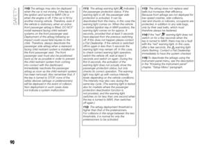 92
92 93
93 94
94 95
95 96
96 97
97 98
98 99
99 100
100 101
101 102
102 103
103 104
104 105
105 106
106 107
107 108
108 109
109 110
110 111
111 112
112 113
113 114
114 115
115 116
116 117
117 118
118 119
119 120
120 121
121 122
122 123
123 124
124 125
125 126
126 127
127 128
128 129
129 130
130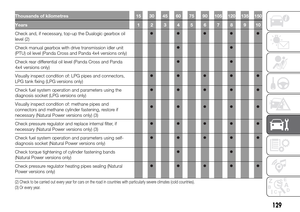 131
131 132
132 133
133 134
134 135
135 136
136 137
137 138
138 139
139 140
140 141
141 142
142 143
143 144
144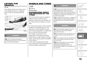 145
145 146
146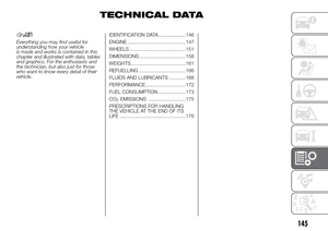 147
147 148
148 149
149 150
150 151
151 152
152 153
153 154
154 155
155 156
156 157
157 158
158 159
159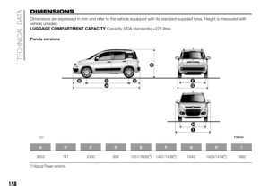 160
160 161
161 162
162 163
163 164
164 165
165 166
166 167
167 168
168 169
169 170
170 171
171 172
172 173
173 174
174 175
175 176
176 177
177 178
178 179
179 180
180 181
181 182
182 183
183 184
184 185
185 186
186 187
187 188
188 189
189 190
190 191
191 192
192 193
193 194
194 195
195 196
196 197
197 198
198 199
199 200
200 201
201 202
202 203
203 204
204 205
205 206
206 207
207 208
208 209
209 210
210 211
211 212
212 213
213 214
214 215
215