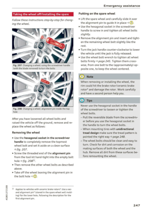
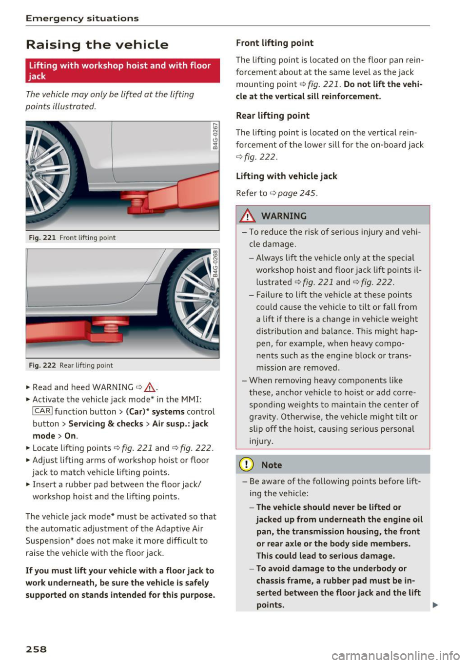
Page 257 of 284

@ Tips
The discharged battery must be properly con
nected to the vehicle's electrical system .
When jump starting or charg ing the battery,
never connect the negative ground cable to
the battery negative post because the battery
manager system must be able to detect the
battery's state of charge. Always connect the
negative ground cable to the negative ground
post of the battery manager control unit.
Use of jumper cables
Make sure to connect the jumper cable clamps in
exactly the order described below!
Fig. 214 Engine compartment: connectors fo r ju mp start
cables and charger
® @
Fig. 215 Jump starting with the battery of another vehicle:
@-booste r battery, @-discharged veh icle batte ry
The procedure described below for connecting
jumper cables is intended to provide a jump start
for your vehicle .
Vehicle with discharged battery:
.. Turn off lights and accessories, move lever of
~ automatic transmission to N (Neutral) or P ....
~ (Park) and set parking brake . N .... 0
00
<.,;) 'SI"
Emergency situations
Connect POSITIVE(+) to POSITIVE (+) (red)
.. Open the red cover on the pos itive terminal
qfig. 214.
1. Connect one end of the red posit ive cab le on
the jump start bolt~
fig. 215 (D (bolt under
the red cover= "positive") of the vehicle to be
started @.
2. Connect the other end to the positive termi- nal@ of the booster battery @.
Connect NEGATIVE (-) to NEGATIVE (-)
(black)
3. Connect one end of the black negative cable
to the negative terminal ® of the booster
battery @.
4. Connect the other end to the jump start pin
@ (bolts with hex head bolt= "negat ive'') of
the vehicle to be started @.
Starting the engine
.. Start the engine of the vehicle with the booster
battery @. Run the eng ine at a moderate
speed .
.. Start engine w ith discharged vehicle battery@
in the usual manner .
.. If the engine fails to start, do not keep the
starter cranking for longer than 10 seconds.
Wait for about 30 seconds and then try again .
.. With engine running, remove jumper cables
from both vehicles in the exact
reverse order .
.. Close the red cover on the positive terminal.
The battery is vented to the outside to prevent gases from entering the vehicle interior . Make
sure that the jumper clamps are well connected
with their metal parts in full contact with the battery terminals .
_&. WARNING
To avoid serious personal injury and damage
to the vehicle, heed all warnings and instruc
tions of the jumper cable manufacturer. If in
doubt, call for road service.
- Jumper cables must be long enough so that
the vehicles do not touch .
- When connecting jumper cables, make sure
that they cannot get caught in any moving
parts in the engine compartment. ..,.
255
Page 258 of 284

Emergency situations
-Before you check anything in the engine
compartment, always read and heed all
WARNINGS
c> page 199.
(D Note
Improper hook-up of jumper cables can ruin
the generator.
-Always connect POSITIVE(+) to POSITIVE
(+), and NEGATIVE(-) to NEGATIVE(-)
ground post of the battery manager control
unit.
- Check that all screw plugs on the battery
cells are screwed in firmly. If not, tighten
plugs prior to connecting clamp on negative
battery terminal.
- Please note that the procedure for connect
ing a jumper cable as described above ap
plies specifically to the case of your vehicle
being jump started . When you are giving a
jump start to another vehicle, do
not con
nect the negative (-) cable to the negative
(-) terminal on the discharged battery @
c> fig. 215. Instead, securely connect the
negative(-) cable to either a solid metal
component that is firmly bolted to the en
gine block or to the engine block itself. If
the battery that is being charged does not
vent to the outside, escaping battery gas
could ignite and explode!
Towing with a tow truck
General hints
Your Audi requires special handling for towing.
The following information is to be used by com
mercial tow truck operators who know how to op
erate their equipment safely.
- Never tow your Audi. Towing will cause dam
age to the engine and transmission.
- Never wrap the safety chains or winch cables
around the brake lines.
- To prevent unnecessary damage, your Audi
must be transported with a flat bed truck.
- To load the vehicle on to the flat bed, use the
towing loop found in the vehicle tools and at-
256
tach to the front or rear anchorage
c>page 256 and ¢page 257.
A WARNING
A vehicle being towed is not safe for passen
gers . Never allow anyone to ride in a vehicle
being towed, for any reason.
Front towing loop
Fig. 216 Front bumper: cover
Fig. 217 Front bumpe r: install ing the tow ing loop
The threaded opening for the towing loop is lo
cated behind a cover on the right side of the front
bumper .
.. Remove the towing loop from the vehicle tool
kit
c> page 240.
.. Press the cap inward with brief, forceful pres
sure
¢fig. 216. The cap will loosen from the
bumper.
.. Tighten the towing loop in the threaded open
ing until it stops
¢ fig. 217 and then tighten it
with a wheel wrench .
.. After using, place the towing loop back in the
vehicle tool kit.
IJli>
Page 259 of 284

co
co
.... N
" N .... 0
00
<..:l 'SI'
_& WARNING
If the towing loop is not tightened until it
stops when installing, the threads may be
pulled out when tow ing the veh icle and that
could cause an acc ident .
Rear towing loop
0 0
Fig. 218 Rear bumper : cove r
0 0
Fig. 219 Rea
r bumper : installing the towing loop
The threaded opening is located in the bumper
on the right rear side.
.,. Remove the towing loop from the vehicle tool
kit¢
page 240 .
.,. Press the cap inward with brief, forceful pres
sure ¢
fig. 218. The cap will loosen from the
bumper .
.,. Tighten the towing loop in the th readed open
ing until it stops ¢
fig. 219 and then tighten it
with a wheel wrench .
.,. After using, place the towing loop back in the
vehicle tool kit.
_& WARNING
If the towing loop is not tightened until it
stops when installing , the threads may be
-
Emergency situations
pulled out when towing the vehicle and that
could cause an accident.
Loading the vehicle onto a flat bed truck
Fig. 220 Vehicle on flat bed truck
Front hook up
.,. Alig n the vehicle with the centerline of the car
carrier ramp .
.,. Attach the winch hook to the front towline eye
previously installed .
Rear hook up
.,. Align the vehicle with the centerl ine of the car
carrier ramp .
.,. Attach the winch hook to the rear towline eye
previously installed.
(D Tips
Check carefully to make sure the hook-up is
secure before moving the car up the flatbed
truck ramp .
257
Page 260 of 284

Emergency situations
Raising the vehicle
Lifting with workshop hoist and with floor
jack
Th e vehicle may only b e lift ed at the lifting
poin ts illust rated.
F ig .. 221 F ro nt lift ing po int
F ig. 222 Rea r lifti ng po int
.,. Read and heed WARNING c::> A -
.,. Activate the vehicle jac k mode* in the MMI:
I CAR I funct io n button > (Car) * systems co ntro l
button
> Servicing & checks > Air susp. : jack
mode > On .
.,. Lo ca te lift ing po ints c::> fig . 221 a nd c::> fig . 222 .
.,. Adjus t lifting arms of wo rk shop hoist o r floo r
jac k to m atch veh icle li fting poin ts.
.,. Inse rt a rubber pa d between the floor jack/
wor kshop hoist an d the lifting points .
Th e ve hicle jack mode* must be activa ted so that
the au tom atic a djustment of the Ad aptive Air
S uspens ion* does no t make it more d ifficult to
raise the ve hicle w ith the floor jac k.
If you must lift your vehicle with a floor jack to
work underneath, be sure the vehicle is safely
supported on stands intended for this purpose.
258
Front lifting point
The li fting point is lo cated on the floor pa n rein
f orcement about at the same level as the ja ck
mounting point
c::> fig . 221. Do not lift the vehi
cle at the vertical sill reinforcement.
Rear lifting point
The lif ting poin t is loca ted on the ve rtic al rein
forcement of t he lower sill for the o n-b o ard jack
c::>fig. 22 2.
Lifting with vehicle jack
Refer to c::> page 245 .
A WARNING
-To red uce the r is k of se rious inju ry and vehi
cle damage.
- Always lift the vehicle on ly at the special
workshop hoist an d floor jack lift points il
l ustrated
c::> fig. 221 and c::> fig. 222.
- Fail ure to lift the ve hicle at these points
could cause the vehicle to t ilt o r fall from
a lift i f there is a cha nge in ve hicle we ight
dist ribution and balance . This might hap
pen, fo r example, wh en heavy compo
n en ts such as the eng ine block o r tra ns
m iss ion are re moved .
- Whe n rem oving heavy co m po nents like
t hese, an chor vehicle to hois t or add cor re
s p ondin g weig hts to maintai n the cen ter of
gravi ty . O th erw ise, the vehicle might t ilt or
slip off the hoist, causi ng serio us pers onal
in jur y .
(D Note
- B e aw are of the follo wing p oints bef ore lift
ing the vehicle :
-The vehicle should never be lifted or
jacked up from underneath the engine oil
pan, the transmission housing, the front
or rear axle or the body side members.
This could lead to serious damage .
- To avoid damage to the underbody or
chassis frame, a rubber pad must be in
serted between the floor jack and the lift
points.
Page 261 of 284
co
co
.... N ,..._
N .... 0
00
\.J '
-Before driving over a workshop hoist,
check that the vehicle weight does not
exceed the permissible lifting capacity of
the hoist.
- Before driving over a workshop hoist, en
sure that there is sufficient clearance be
tween the hoist and low parts of the ve
hicle.
Vehicle carrier
(D Note
Wh en transporting the vehicle o n a ca r carri
er, tra in, sh ip or by ot her means, only t ie the
veh icle d ow n at th e runnin g surfa ce of the
t ires, w hich is t he outer circumference. Secur
in g the vehicle at the axle components, sus
pens ion struts or tow ing eyes is not pe rm itted
because the pressure in the air suspens ion
struts can change du ring transpo rt . The vehi
cle may not be secured suff ic ient ly if this hap
pe ns.
Emergency situations
259
Page 262 of 284

Technical data
Technical data
Vehicle specifications
Fig. 223 Windshiel d (fro nt left) : Ve hicl e Iden tific ation
N um ber ( VIN )
XXXXX XX -X -XXXX XXX XX
@-+ ~:~t::1 ::: xxxxxxxx xx x xxxxxxxx
I YP lf'VPE XXX XXX
XX XXXXXXX XX X X XX
XXX
KW XXX
15\_L I MOIOlll
@-+ ~~
1
:tr:~i XXXX I XXXX XXX I XX
II. -AUSST . / OPTIONS
.__ __
E0A 7D5 4UB
2EH J0Z lLB
3FC F0 A 9G3
T L6 3 KA BEH
lXW 803
7T6 CV7 7K0
3L4 4KC
lS A 7GB
6XM SSG
lAS
SMU 7Xl
0G7 0YH
UlA X9B
908 8Z4
4X3
2K2
3Y0 413
01A
SR W
1BA
OJF
027
020
502
4G0
XX X XX X XX X XXXX
Fig. 224 Vehicle identification label
Vehicle Identification Number (VIN)
The VIN numbe r is located in the following pla
ces :
- In the Infotainment system: select: the!CAR !
funct ion button
> (Car)* systems control but
ton
> Serve & checks > VIN number .
-on the vehicle identification label
- under the windshield on the driver's side*
260
Vehicle identification label
The vehicle identification label¢ fig. 224 is locat
ed in the luggage compartment under the cargo
floor cover.
The information of the vehicle identification label
can also be found in your Warranty
& Mainte
nance booklet.
The sticker contains the follow ing vehicle data:
(D Vehicle Iden tifica tion Number (VIN)
@ Vehicle type, eng ine output, transmission
® Engin e and transm ission cod es
@ Paint and interior codes
® Optional equipment numbe rs
Safety compliance sticker
The safety compliance sticker is your assurance
that your new vehicle complies with all applicable
Federal Motor Vehicle Safety Standards which
were in effect at the time the vehicle was manu
factured. You can find this sticker on the door
jamb on the dr iver's side . It shows the month and
y ear of production and the vehicle identification
number of you r vehicle (perforation) as well as
the G ross Veh icle Weight R ating (GVWR) and the
Gro ss Axle Weight Rating (GAWR).
H igh voltage warning label
The high voltag e warn ing label is located in the
e ngine compartment n ext to the engine hood re
lease. The spark ignit ion system complie s w ith
the Canad ian s tand ard IC ES-002.
Notes about technical
data
The values may differ for some markets depend
ing on equipment installed in certain markets
and the measur ing methods .
Plea se note that the specifications listed in the
vehicle documentation a lways take precedence .
(D Tips
Missing technical data was not available at
the time of printing .
Page 263 of 284

Weights
Gross Vehi cle We ight Rating
The G ross Veh icle Weight Rating (GVWR), and
the Gross Axle Weight Rating (GAWR) for front
and rear are listed on a sticker on the door jamb
on the driver's side.
The G ross Veh icle Weight Rating includes the
weight of the basic vehicle p lus full fuel tank, oi l
and coolant, p lus maximum load, which includes
passenger weight (150 lbs/68 kg per designated
seating position) and luggage we ight
c:> A .
Gross Axle Weight Rating
The Gross Axle We ight Rating is the max imum
l oad that can be applied at each axle of the vehi
cle
c:> &, .
Vehicle capacity weight
The vehicle capac ity we ight (max . load) is listed
e ithe r o n the dr iver's side 8-pilla r or inside the
fuel filler f lap .
A WARNING
-
-The actual Gross Ax le Weight Rating at the
front and rear axles sho uld not exceed the
permissible weights, and their comb inat ion
must not exceed the Gross Vehicle We ight
Rating.
- Exceeding perm iss ible weight ratings can
result in vehicle damage, acc idents and per
sonal inj ury .
Dimensions
Techn ical data
(D Note
- The vehicle capacity weig ht figures apply
when the load is d istributed evenly in the
vehicle (passengers and luggage). When
transport ing a heavy load in the luggage
compartment, carry the load as near to the
rear axle as possible so that the vehicle's
hand ling is no t impa ired .
- Do not exceed the maximum perm iss ible
ax le loads or the maximum gross vehicle
we igh t. A lways remember that the vehi cle's
hand ling will be affected by the extra load.
T he refore, adjust your speed acco rd ingly.
- Always observe lo cal regulations.
Length (in (mm)) Width (in (mm ))
Width across the Height at curb
A7 Sportback 196.2 (4,984)
RS 7 Sportback 197
.3 (5,012)
S7 Spo rtback 196.3 (4,985)
W hen driving on poor roads, by curbs and on
steep ramps, make sure that low-hang ing com
ponents such as the spo ile r and exhaust system
mirrors (in (mm)) weight (in (mm))
75 .2 ( 1,911) 84.2 (2,139) 55 .9 ( 1,420)
75 .2 (1,911) 84 .2 ( 2,139) 55 .9 ( 1,419)
75 .2 ( 1,911) 84.2 (2,139) 55.0 ( 1,398)
be damaged . This especially applies to vehicles
that are eq uipped w ith adapt ive a ir suspension*
and when the vehicle is at full load .
co ~ do not come into contact with these o r they could
N
" N ..... 0
00
\.J '
261
Page 264 of 284
Tech nical data
Capacities
Appro ximate capaci -
ties
Gasoline engine fuel tank 19.8 gal (75.0 L)
Diesel engine fuel tank 19.3 gal (73
.0 L)
Windshield washer system 3.7 qt (3.5
L)
Windshield and headlight washe r system* 5.2 qt (4.9 L)
Gasoline engines
A7 3.0, 6 cylinder
Maximum output SAE net
hp@rpm 333 @ 5300 - 6500
Maximum torque SAE net lb-ft@ rpm 325@ 2900 - 5300
Displacement CID (cm
3
) 182 (2995)
Engine oil with filter change
1l
Fuel
Premium unl eaded (91 AKI) , ¢page 191, Fuel supply
This vehicle is available with different specifica
tions in some markets (see car documentation).
57 4.0 , 8 cylinder
Maximum output SA E net hp@ rpm
Max imum torque SAE net lb-ft@ rpm
Displacement C
ID (cm
3
)
Engine o il w ith filter change1l 450 @ 5800 - 6400
406@ 1400
-5700
243.7 (3993)
Fuel
Premium unleaded (91 AKI) , ¢page 191, Fuel supply
262