Page 25 of 128

2-5
2
4. Once immediate safety hazards are con-
firmed not to exist, you may remove your hel-
met to more closely inspect your vehicle.
Check for external signs of wear, broken
parts, fluid leaks, cracks in the frame, sus-
pension damage, wheel damage, and so on.
Fuel, oil, and coolant usually give off a notice-
able odor.
5. If your vehicle will not restart or if it is unsafe to ride, then turn off all vehicle systems (en-
gine stop switch, main switch, and fuel cock),
and then signal or go for help.
Aftermarket Parts, Accessories, and Modifica-
tions
While you may find aftermarket products similar in
design and quality to genuine Yamaha accesso-
ries, recognize that some aftermarket accessories
or modifications are not suitable because of po-
tential safety hazards to you or others. Installing
aftermarket products or having other modifica-
tions performed to your vehicle that change any of
the vehicle’s design or operation characteristics
can put you and others at greater risk of serious
injury or death. You are responsible for injuries re- lated to changes in the vehicle. Keep the following
guidelines in mind, as well as those provided un-
der “Loading” when mounting accessories.
Never install accessories that would impair the
performance of your ATV. Carefully inspect the
accessory before using it to make sure that it
does not in any way reduce ground clearance,
limit suspension travel, steering travel or control
operation.
Accessories fitted to the ATV can create insta-
bility due to improper weight distribution.
Bulky or large accessories may seriously affect
the stability of the ATV.
Certain accessories can displace the operator
from his or her normal riding position. This im-
proper position limits the freedom of movement
of the operator and may limit control ability,
therefore, such accessories are not recom-
mended.
Use caution when adding electrical accesso-
ries. If electrical accessories exceed the capac-
ity of the ATV’s electrical system, an electric
failure could result, which could cause a dan-
gerous loss of lights or engine power.
UBD360E0.book Page 5 Wednesd ay, February 25, 2015 2:41 PM
Page 26 of 128

2-6
2
WARNING
EWB00073Avoid Carbon Monoxide Poisoning
All engine exhaust contains carbon monoxide,
a deadly gas. Breathing carbon monoxide can
cause headaches, dizziness, drowsiness, nau-
sea, confusion, and eventually death.
Carbon Monoxide is a colorless, odorless,
tasteless gas which may be present even if you
do not see or smell any engine exhaust. Deadly
levels of carbon monoxide can collect rapidly
and you can quickly be overcome and unable
to save yourself. Also, deadly levels of carbon
monoxide can linger for hours or days in en-
closed or poorly ventilated areas. If you experi-
ence any symptoms of carbon monoxide
poisoning, leave the area immediately, get
fresh air, and SEEK MEDICAL TREATMENT.
Do not run engine indoors. Even if you try to
ventilate engine exhaust with fans or open
windows and doors, carbon monoxide can
rapidly reach dangerous levels.
Do not run engine in poorly ventilated or par-
tially enclosed areas such as barns, garages,
or carports.
Do not run engine outdoors where engine
exhaust can be drawn into a building through
openings such as windows and doors.
WARNING
EWB02592When transporting the ATV in another vehicle,
be sure it is kept upright and that the fuel cock
is in the “OFF” position. Otherwise, fuel may
leak out of the carburetor or fuel tank.
UBD360E0.book Page 6 Wednesd ay, February 25, 2015 2:41 PM
Page 27 of 128
3-1
3
EBU17681
DESCRIPTION
EBU17691Left view
EBU17701Right view
1. Fuel tank cap
2. Fuel cock
3. Air filter
4. Fuse
5. Battery
6. Rear shock absorber assembly spring preload adjusting ring
7. Kickstarter lever cap
1 2 3 4,5
76
1. Spark arrester
2. Owner’s tool kit
3. Front shock absorber assembly spring preload adjusting ring
4. Spark plug
5. Engine oil filler cap
6. Transmission oil filler cap
12 3
65 4
UBD360E0.book Page 1 Wednesd ay, February 25, 2015 2:41 PM
Page 28 of 128
3-2
3
EBU17714Controls and instrumentsTIPThe ATV you have purchased may differ slightly
from the figures shown in this manual. 1. Rear brake lever
2. Handlebar switches
3. Parking brake lock plate
4. Starter (choke)
5. Main switch
6. Throttle lever
7. Front brake lever
8. Drive select lever
1
2
3
5
6
7
4
8
UBD360E0.book Page 2 Wednesday, February 25, 2015 2:41 PM
Page 29 of 128
4-1
4
EBU17737
INSTRUMENT AND CONTROL FUNCTIONS
EBU33850Main switchThe positions of the main switch are as follows:
ON
All electrical systems are supplied with power, and
the engine can be started. The key cannot be re-
moved.
OFF
All electrical systems are off. The key can be re-
moved.
EBU17794Indicator lightsEBU17861Neutral indicator light “ ”
This indicator light comes on when the transmis-
sion is in the neutral position.EBU17831Reverse indicator light “ ”
This indicator light comes on when the transmis-
sion is in the reverse position.
ON
OFF
1. Reverse indicator light “R”
2. Neutral indicator light “N”
1
2
UBD360E0.book Page 1 Wednesd ay, February 25, 2015 2:41 PM
Page 30 of 128
4-2
4
EBU18065Handlebar switchesEBU18081Engine stop switch “ / ”
Set this switch to “ ” before starting the engine.
The engine stop switch controls the ignition and
stops the engine when it is running. Use this
switch to stop the engine in an emergency situa-
tion. The engine will not start or run when this
switch is set to “ ”.
EBU18102Start switch “ ”
Push this switch to crank the engine with the start-
er. See the starting instructions on page 6-1 prior
to starting the engine.EBU18283Throttle leverOnce the engine is running, pushing the throttle le-
ver will increase the engine speed.
Regulate the speed of the ATV by varying the
throttle position. Because the throttle is spring-
loaded, the ATV will decelerate, and the engine
will return to an idle any time the throttle lever is re-
leased.
1. Engine stop switch “ / ”
2. Start switch “ ”
21
1. Throttle lever
1
UBD360E0.book Page 2 Wednesday, February 25, 2015 2:41 PM
Page 31 of 128

4-3
4
Before starting the engine, check the throttle to be
sure it is operating smoothly. Make sure it returns
to the idle position as soon as the lever is released.
EBU33801Speed limiterYour ATV was delivered with two speed limiter de-
vices. A vehicle speed limiter adjusting screw and
a removable engine speed limiter plate. Yamaha
recommends that all beginning riders start off with
the vehicle speed limiter adjusting screw fully
turned in and the engine speed limiter plate in-
stalled to limit the amount of speed available while
they learn.
The vehicle speed limiter keeps the throttle from
fully opening, even when the throttle lever is
pushed to the maximum. The adjusting screw may
be gradually turned out as the beginner becomes
more familiar with operating the ATV. Parents
should decide when to adjust the ATV for more
power as their youngster’s riding skills improve.
Once the ATV rider can operate with skill at the top
speed permitted by adjusting the vehicle speed
limiter alone, the engine speed limiter plate can be
removed. Since removal of this plate will result in
a significant increase in power, turn the vehicle speed limiter adjusting screw completely back in
again and adjust it out in stages as done previous-
ly.
Vehicle speed limiter
1. Loosen the locknut.
2. To increase the maximum engine power available and the maximum speed of the ATV,
turn the adjusting screw in direction (a). To
decrease the maximum engine power avail-
able and the maximum speed of the ATV, turn
the adjusting screw in direction (b). Do not
turn the adjusting screw out more than 10
mm (0.39 in) or the throttle cable could be
damaged. Always make sure the throttle lever
free play is adjusted to 1.5–4.0 mm (0.06–
0.16 in). (See page 8-20.) WARNING! Im-
proper adjustment of the speed limiter and
throttle could cause throttle cable damage
or improper throttle operation. You could
lose control, resulting in an accident.
[EWB00242]
UBD360E0.book Page 3 Wednesd ay, February 25, 2015 2:41 PM
Page 32 of 128
4-4
43. Tighten the locknut.
Engine speed limiter plate
When the engine speed limiter plate is installed,
engine speed is limited to 4900 r/min. When this
plate is removed, top engine speed (8500 r/min) is
available.
Remove the plate as follows. 1. Remove the seat. (See page 4-12.)
2. Loosen the screws, and then remove the plate as shown. 3. Tighten the screws.
4. Install the seat.
TIPStore the engine speed limiter plate with the own-
er’s manual so that it is readily available whenever
you want to reduce top engine speed. EBU18392Front brake leverThe front brake lever is located on the right han-
dlebar. To apply the front brake, pull the brake le-
ver toward the handlebar grip.
1. Locknut
2. Adjusting screw
3. No more than 10 mm (0.39 in)
1
3
2
(b)
(a)
1. Screw
2. Engine speed limiter plate
12
UBD360E0.book Page 4 Wednesd ay, February 25, 2015 2:41 PM
 1
1 2
2 3
3 4
4 5
5 6
6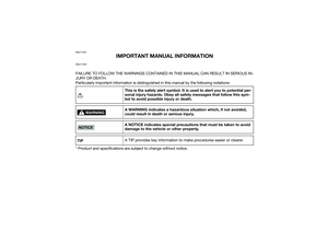 7
7 8
8 9
9 10
10 11
11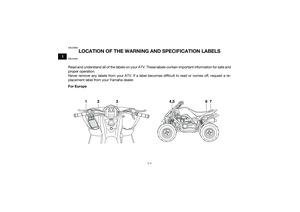 12
12 13
13 14
14 15
15 16
16 17
17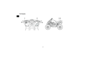 18
18 19
19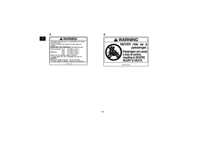 20
20 21
21 22
22 23
23 24
24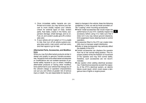 25
25 26
26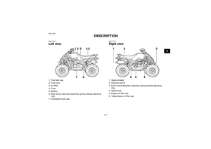 27
27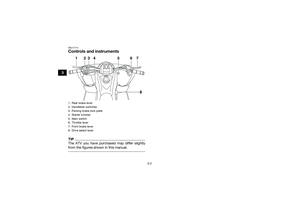 28
28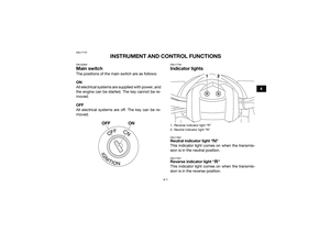 29
29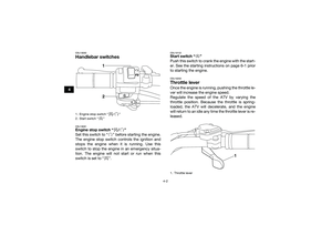 30
30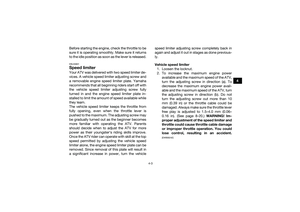 31
31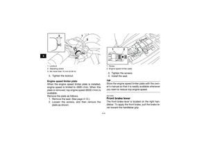 32
32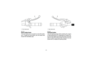 33
33 34
34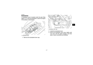 35
35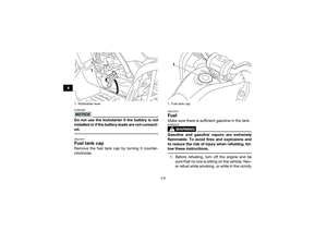 36
36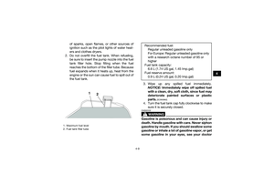 37
37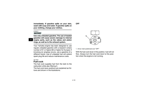 38
38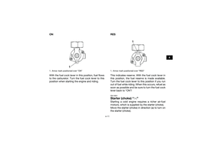 39
39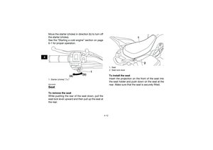 40
40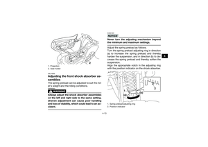 41
41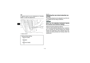 42
42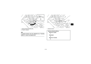 43
43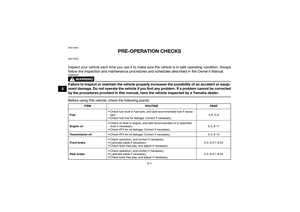 44
44 45
45 46
46 47
47 48
48 49
49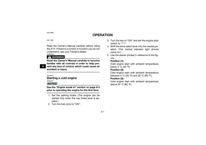 50
50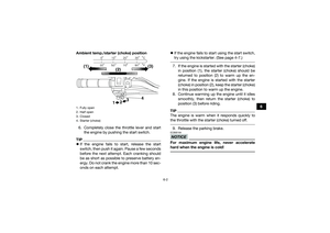 51
51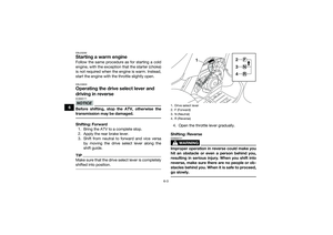 52
52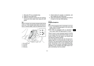 53
53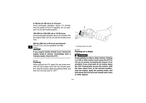 54
54 55
55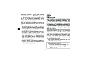 56
56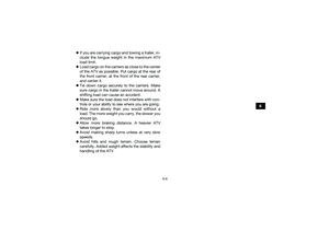 57
57 58
58 59
59 60
60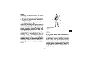 61
61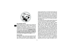 62
62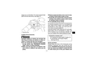 63
63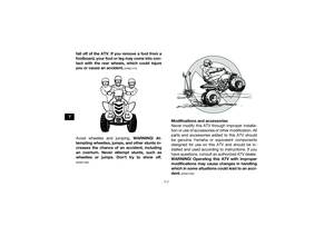 64
64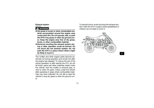 65
65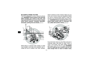 66
66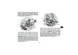 67
67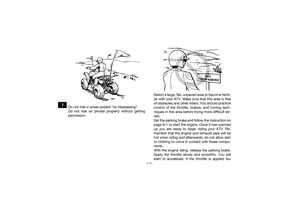 68
68 69
69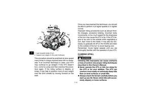 70
70 71
71 72
72 73
73 74
74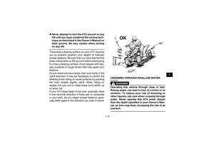 75
75 76
76 77
77 78
78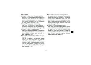 79
79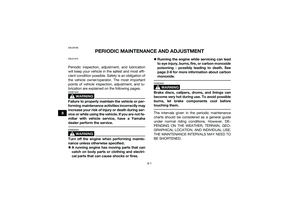 80
80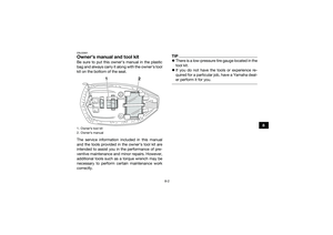 81
81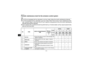 82
82 83
83 84
84 85
85 86
86 87
87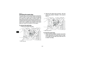 88
88 89
89 90
90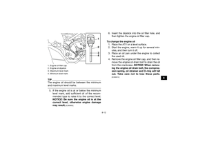 91
91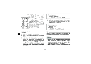 92
92 93
93 94
94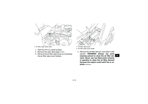 95
95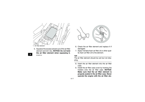 96
96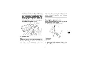 97
97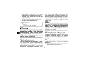 98
98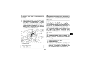 99
99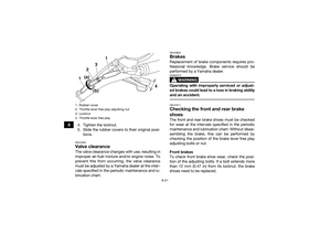 100
100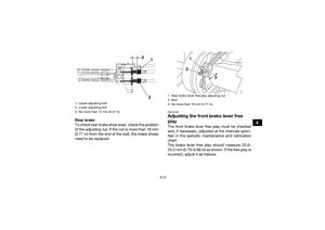 101
101 102
102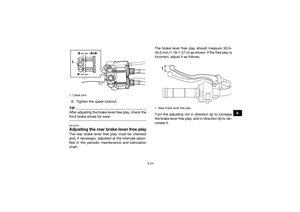 103
103 104
104 105
105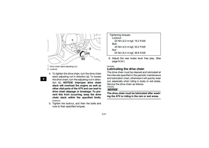 106
106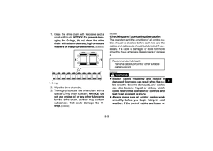 107
107 108
108 109
109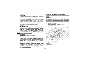 110
110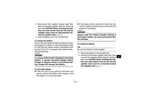 111
111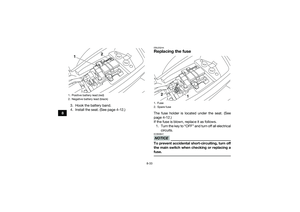 112
112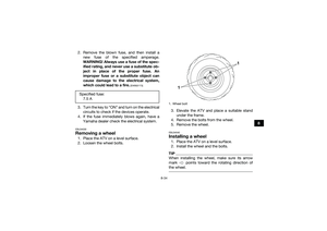 113
113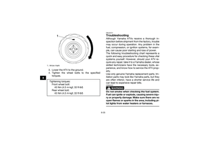 114
114 115
115 116
116 117
117 118
118 119
119 120
120 121
121 122
122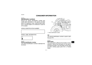 123
123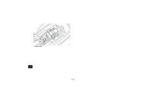 124
124 125
125 126
126 127
127


