Page 73 of 110

Periodic maintenance and adjustment
7-16
1
2
3
4
5
6
7
8
9
10
11
12
13
14
EAU33483
Adjusting the engine idling
speed
The engine idling speed must be
checked and, if necessary, adjusted as
follows at the intervals specified in the
periodic maintenance and lubrication
chart.
The engine should be warm before
making this adjustment. 1. Remove panel D. (See page 7-7.)
2. Check the engine idling speed and, if necessary, adjust it to spec-
ification by turning the idle adjust-
ing screw. To increase the engine
idling speed, turn the screw in di-
rection (a). To decrease the en-
gine idling speed, turn the screw in
direction (b).
TIP
If the specified idling speed cannot be
obtained as described above, have a
Yamaha dealer make the adjustment.
3. Install the panel.
EAU21386
Checking the throttle grip free
play
Measure the throttle grip free play as
shown.
Periodically check the throttle grip free
play and, if necessary, have a Yamaha
dealer adjust it.
1. Idle adjusting screw
Engine idling speed: 1100–1300 r/min
1(a)(b)
1. Throttle grip free play
Throttle grip free play:
3.0–5.0 mm (0.12–0.20 in)
1
2PW-9-E1.book 16 ページ 2015年9月10日 木曜日 午後5時17分
Page 74 of 110

Periodic maintenance and adjustment
7-17
1
2
3
4
5
6
7
8
9
10
11
12
13
14
EAU21402
Valve clearance
The valve clearance changes with use,
resulting in improper air-fuel mixture
and/or engine noise. To prevent this
from occurring, the valve clearance
must be adjusted by a Yamaha dealer
at the intervals specified in the periodic
maintenance and lubrication chart.
EAU65120
Tires
Tires are the only contact between the
vehicle and the road. Safety in all con-
ditions of riding depends on a relatively
small area of road contact. Therefore, it
is essential to maintain the tires in good
condition at all times and replace them
at the appropriate time with the speci-
fied tires.
Tire air pressure
The tire air pressure should be checked
and, if necessary, adjusted before each
ride.
WARNING
EWA10504
Operation of this vehicle with im-
proper tire pressure may cause se-
vere injury or death from loss of
control.
The tire air pressure must be
checked and adjusted on cold
tires (i.e., when the temperature
of the tires equals the ambient
temperature).
The tire air pressure must be ad-
justed in accordance with the
riding speed and with the total
weight of rider, passenger, car-
go, and accessories approved
for this model.
2PW-9-E1.book 17 ページ 2015年9月10日 木曜日 午後5時17分
Page 75 of 110

Periodic maintenance and adjustment
7-18
1
2
3
4
5
6
7
8
9
10
11
12
13
14
WARNING
EWA10512
Never overload your vehicle. Opera-
tion of an overloaded vehicle could
cause an accident.
Tire inspection
The tires must be checked before each
ride. If the center tread depth reaches
the specified limit, if the tire has a nail or
glass fragments in it, or if the sidewall is
cracked, have a Yamaha dealer re-
place the tire immediately.
TIP
The tire tread depth limits may differ
from country to country. Always comply
with the local regulations.
WARNING
EWA10472
Have a Yamaha dealer replace
excessively worn tires. Besides
being illegal, operating the vehi-
cle with excessively worn tires
decreases riding stability and
can lead to loss of control.
The replacement of all wheel
and brake-related parts, includ-
ing the tires, should be left to a
Yamaha dealer, who has the
necessary professional knowl-
edge and experience to do so.
Ride at moderate speeds after
changing a tire since the tire
surface must first be “broken
in” for it to develop its optimal
characteristics.
Tire information
This model is equipped with tubeless
tires and tire air valves.
Tires age, even if they have not been
used or have only been used occasion-
ally. Cracking of the tread and sidewall
rubber, sometimes accompanied by
carcass deformation, is an evidence of
ageing. Old and aged tires shall be
checked by tire specialists to ascertain
their suitability for further use.
Tire air pressure (measured on cold
tires): Up to 90 kg (198 lb) load:Front: 225 kPa (2.25 kgf/cm
2, 33 psi)
Rear: 250 kPa (2.50 kgf/cm
2, 36 psi)
90 kg (198 lb) to maximum load:
Front: 225 kPa (2.25 kgf/cm
2, 33 psi)
Rear:
280 kPa (2.80 kgf/cm
2, 41 psi)
Maximum load*: 193 kg (425 lb) (XP500A)
196 kg (432 lb) (XP500)
* Total weight of rider, passenger, car- go and accessories
1. Tire sidewall
2. Tire tread depth
1 2
Minimum tire tread depth (front and
rear):
1.6 mm (0.06 in)
2PW-9-E1.book 18 ページ 2015年9月10日 木曜日 午後5時17分
Page 76 of 110

Periodic maintenance and adjustment
7-19
1
2
3
4
5
6
7
8
9
10
11
12
13
14
WARNING
EWA16101
The front and rear tires should
be of the same make and de-
sign, otherwise the handling
characteristics of the vehicle
may be different, which could
lead to an accident.
Always make sure that the valve
caps are securely installed to
prevent air pressure leakage.
Use only the tire valves and
valve cores listed below to
avoid tire deflation during a ride.
After extensive tests, only the tires list-
ed below have been approved for this
model by Yamaha.
EAU51921
Cast wheels
To maximize the performance, durabil-
ity, and safe operation of your vehicle,
note the following points regarding the
specified wheels.
The wheel rims should be checked
for cracks, bends, warpage or oth-
er damage before each ride. If any
damage is found, have a Yamaha
dealer replace the wheel. Do not
attempt even the smallest repair to
the wheel. A deformed or cracked
wheel must be replaced.
The wheel should be balanced
whenever either the tire or wheel
has been changed or replaced. An
unbalanced wheel can result in
poor performance, adverse han-
dling characteristics, and a short-
ened tire life.
After repairing or replacing the
front tire, tighten the valve stem nut
and locknut to the specified
torques.
Front tire: Size:120/70R15M/C 56H
Manufacturer/model:
DUNLOP/GPR-100F M
Tire air valve: PVR59A
Valve core: #9100 (original)
Rear tire:
Size:160/60R15M/C 67H
Manufacturer/model:
DUNLOP/GPR-100 M
Tire air valve: TR412
Valve core: #9100 (original)
1. Valve stem nut
2. Valve stem locknut
Tightening torques:Valve stem nut:
2.0 Nm (0.2 m·kgf, 1.4 ft·lbf)
Valve stem locknut: 3.0 Nm (0.3 m·kgf, 2.2 ft·lbf)
1
2
2PW-9-E1.book 19 ページ 2015年9月10日 木曜日 午後5時17分
Page 77 of 110
Periodic maintenance and adjustment
7-20
1
2
3
4
5
6
7
8
9
10
11
12
13
14
EAU50861
Checking the fr ont and rear
brake lever free play
Front
Rear
There should be no free play at the
brake lever ends. If there is free play,
have a Yamaha dealer inspect the
brake system.
WARNING
EWA14212
A soft or spongy feeling in the brake
lever can indicate the presence of air
in the hydraulic system. If there is air
in the hydraulic system, have a
Yamaha dealer bleed the system be-
fore operating the vehicle. Air in the
hydraulic system will diminish the
braking performance, which may re-
sult in loss of control and an acci-
dent.
1. No brake lever free play
1. No brake lever free play
1
1
2PW-9-E1.book 20 ページ 2015年9月10日 木曜日 午後5時17分
Page 78 of 110

Periodic maintenance and adjustment
7-21
1
2
3
4
5
6
7
8
9
10
11
12
13
14
EAU53032
Adjusting the rear brake lock
cable
Rear brake lock cable adjustment may
be required if the rear brake lock lever
does not hold properly. When the rear
brake lock lever is not in use, the rear
brake lock cable length should mea-
sure 43–45 mm (1.69–1.77 in) at the
rear brake caliper.
Periodically check the rear brake lock
cable length and, if necessary, adjust it
as follows.
To increase the rear brake lock cable
length, turn the adjusting nut at the rear
brake caliper in direction (a). To de-
crease the rear brake lock cable length,
turn the adjusting nut in direction (b).
WARNING! If proper adjustment
cannot be obtained as described,
have a Yamaha dealer make this ad-
justment.
[EWA16151]
Check that the rear brake lock is re-
leased, and then make sure that the
rear wheel could rotate smoothly.
EAU52293
Checking the rear brake lock
The rear brake lock must be checked at
the intervals specified in the periodic
maintenance and lubrication chart. 1. Adjust the rear brake lock cable.
2. Apply the rear brake lock, and then try to push the vehicle to confirm
that the rear brake lock functions
properly.
3. The rear brake lock caliper is pro- vided with a wear indicator, which
allows you to check the rear brake
lock pads. To check the rear brake
lock pads, check the position of the
indicator when the rear brake lock
lever is applied. If the indicator has
passed the wear indicator groove,
have a Yamaha dealer check the
rear brake lock.
4. Make sure that there are no tears or cracks on the rubber boot.
1. Adjusting nut
2. Rear brake lock cable length
2
1
(a)
(b)
1. Wear indicator groove
2. Wear indicator
3. Rubber boot
1 23
2PW-9-E1.book 21 ページ 2015年9月10日 木曜日 午後5時17分
Page 79 of 110

Periodic maintenance and adjustment
7-22
1
2
3
4
5
6
7
8
9
10
11
12
13
14
EAU22312
Checking the fr ont and rear
brake pads
Front brake
Rear brake
The front and rear brake pads must be
checked for wear at the intervals spec-
ified in the periodic maintenance and
lubrication chart. Each brake pad is
provided with a wear indicator, which
allows you to check the brake pad wear
without having to disassemble the
brake. To check the brake pad wear,
check the position of the wear indicator
while applying the brake. If a brake pad
has worn to the point that the wear indi-
cator almost touches the brake disc,
have a Yamaha dealer replace the
brake pads as a set.
EAU22582
Checking the brake fluid level
Before riding, check that the brake fluid
is above the minimum level mark.
Check the brake fluid level with the top
of the reservoir level. Replenish the
brake fluid if necessary.
Front brake
Rear brake
WARNING
EWA15991
Improper maintenance can result in
loss of braking ability. Observe
these precautions:
Insufficient brake fluid may al-
low air to enter the brake sys-
tem, reducing braking
performance.
1. Brake pad wear indicator
1. Brake pad wear indicator
1
1
1. Minimum level mark
1. Minimum level mark
Specified brake fluid: DOT 4
1
1
2PW-9-E1.book 22 ページ 2015年9月10日 木曜日 午後5時17分
Page 80 of 110

Periodic maintenance and adjustment
7-23
1
2
3
4
5
6
7
8
9
10
11
12
13
14
Clean the filler cap before re-
moving. Use only DOT 4 brake
fluid from a sealed container.
Use only the specified brake flu-
id; otherwise, the rubber seals
may deteriorate, causing leak-
age.
Refill with the same type of
brake fluid. Adding a brake fluid
other than DOT 4 may result in a
harmful chemical reaction.
Be careful that water does not
enter the brake fluid reservoir
when refilling. Water will signifi-
cantly lower the boiling point of
the fluid and may result in vapor
lock.
NOTICE
ECA17641
Brake fluid may damage painted sur-
faces or plastic parts. Always clean
up spilled fluid immediately.
As the brake pads wear, it is normal for
the brake fluid level to gradually go
down. A low brake fluid level may indi-
cate worn brake pads and/or brake sys-
tem leakage; therefore, be sure to
check the brake pads for wear and the
brake system for leakage. If the brake
fluid level goes down suddenly, have a
Yamaha dealer check the cause before
further riding.
EAU22733
Changing the brake fluid
Have a Yamaha dealer change the
brake fluid at the intervals specified in
the periodic maintenance and lubrica-
tion chart. In addition, have the oil seals
of the master cylinders and calipers as
well as the brake hoses replaced at the
intervals listed below or whenever they
are damaged or leaking.
Oil seals: Replace every two
years.
Brake hoses: Replace every four
years.
2PW-9-E1.book 23 ページ 2015年9月10日 木曜日 午後5時17分
 1
1 2
2 3
3 4
4 5
5 6
6 7
7 8
8 9
9 10
10 11
11 12
12 13
13 14
14 15
15 16
16 17
17 18
18 19
19 20
20 21
21 22
22 23
23 24
24 25
25 26
26 27
27 28
28 29
29 30
30 31
31 32
32 33
33 34
34 35
35 36
36 37
37 38
38 39
39 40
40 41
41 42
42 43
43 44
44 45
45 46
46 47
47 48
48 49
49 50
50 51
51 52
52 53
53 54
54 55
55 56
56 57
57 58
58 59
59 60
60 61
61 62
62 63
63 64
64 65
65 66
66 67
67 68
68 69
69 70
70 71
71 72
72 73
73 74
74 75
75 76
76 77
77 78
78 79
79 80
80 81
81 82
82 83
83 84
84 85
85 86
86 87
87 88
88 89
89 90
90 91
91 92
92 93
93 94
94 95
95 96
96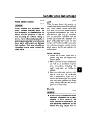 97
97 98
98 99
99 100
100 101
101 102
102 103
103 104
104 105
105 106
106 107
107 108
108 109
109