Page 41 of 110

Instrument and control functions
4-16
1
2
3
4
5
6
7
8
9
10
11
12
13
14
or premium unleaded fuel. Use of un-
leaded fuel will extend spark plug life
and reduce maintenance costs.
Gasohol
There are two types of gasohol: gaso-
hol containing ethanol and that contain-
ing methanol. Gasohol containing
ethanol can be used if the ethanol con-
tent does not exceed 10% (E10). Gas-
ohol containing methanol is not
recommended by Yamaha because it
can cause damage to the fuel system
or vehicle performance problems.
EAU13434
Catalytic converter
This model is equipped with a catalytic
converter in the exhaust system.
WARNING
EWA10863
The exhaust system is hot after op-
eration. To prevent a fire hazard or
burns:
Do not park the vehicle near
possible fire hazards such as
grass or other materials that
easily burn.
Park the vehicle in a place
where pedestrians or children
are not likely to touch the hot
exhaust system.
Make sure that the exhaust sys-
tem has cooled down before do-
ing any maintenance work.
Do not allow the engine to idle
more than a few minutes. Long
idling can cause a build-up of
heat.
NOTICE
ECA10702
Use only unleaded gasoline. The use
of leaded gasoline will cause unre-
pairable damage to the catalytic
converter.
2PW-9-E1.book 16 ページ 2015年9月10日 木曜日 午後5時17分
Page 42 of 110

Instrument and control functions
4-17
1
2
3
4
5
6
7
8
9
10
11
12
13
14
EAU63600
Adjusting the rider backrest
The rider backrest can be adjusted to
the three different positions shown.
Adjust the backrest as follows. 1. Open the seat. (See page 3-10.)
2. Remove the backrest bolts.
3. Slide the backrest forward or back- ward to the desired position.
4. Install and securely tighten the backrest bolts.
5. Close the seat.
EAU63640
Helmet holder
The helmet holder is located under the
seat. A helmet holding cable is provid-
ed beside the owner’s tool kit to secure
a helmet to the helmet holder.
To secure a helmet to the helmet
holder 1. Open the seat. (See page 3-10.)
2. Pass the helmet holding cable through the buckle on the helmet
strap as shown, and then hook the
cable loop over the helmet holder.
3. Make sure the helmet holding ca- ble is not touching the shaded pro-
jection, and securely close the
seat. WARNING! Never ride with
a helmet attached to the helmet
holder, since the helmet may hit
objects, causing loss of control
and possibly an accident.
[EWA10162]
To release the helmet from the hel-
met holder
Open the seat, remove the helmet
holding cable from the helmet holder
and the helmet, and then close the
seat.
1. Rider backrest
1. Rider backrest
2. Bolt
1
1
2
1. Shaded projection
2. Helmet holding cable
3. Helmet holder
3
1
2
2PW-9-E1.book 17 ページ 2015年9月10日 木曜日 午後5時17分
Page 43 of 110

Instrument and control functions
4-18
1
2
3
4
5
6
7
8
9
10
11
12
13
14
EAU63510
Storage compartments
Front storage compartment
To open the storage compartment
when it is locked, insert the mechanical
key into the lock, turn it clockwise, and
then pull the lever up and towards you
to slide the storage compartment open.
To open the storage compartment
when it is unlocked, simply pull on the
lever and slide the compartment open.
To close the storage compartment,
push the lid into the original position.
To lock the storage compartment, push
the lid into the original position, insert
the key into the lock, turn it counter-
clockwise, and then remove the key. Rear storage compartment
A helmet can be stored in the rear stor-
age compartment under the seat. (See
page 3-10 for seat opening and closing
information.) To store a helmet in the
rear storage compartment, place the
helmet upside down with the front fac-
ing to the left side.
NOTICE: The shad-
ed area is not a storage
compartment. To prevent damaging
the seat hinges, do not place any
items in this area.
[ECA16092]
TIP
Some helmets cannot be stored in
the rear storage compartment be-
cause of their size or shape.
Do not leave your scooter unat-
tended with the seat open.
The interior of the rear storage
compartment lies outside the oper-
ating range of the smart key. If the
rear storage compartment is
locked with the smart key inside,
the smart key system may be dis-
abled. The smart key must be car-
ried by the rider.
Do not place the smart key, me-
chanical key, or identification num-
ber tag inside the rear storage
compartment. They may get
1. Front storage compartment
2. Storage compartment opening lever
3. Lock.
1. Lid
1
2
3
1
1. Rear storage compartment
2. Shaded area
1
2
2PW-9-E1.book 18 ページ 2015年9月10日 木曜日 午後5時17分
Page 44 of 110

Instrument and control functions
4-19
1
2
3
4
5
6
7
8
9
10
11
12
13
14 locked inside and the smart key
system may not operate normally.
NOTICE
ECA15963
Do not leave the seat open for
an extended period of time, oth-
erwise the light may cause the
battery to discharge.
Since the storage compartment
may get wet while the scooter is
being washed, wrap any articles
stored in the compartment in a
plastic bag.
To avoid humidity from spread-
ing through the storage com-
partment and to discourage
possible mold growth, wrap wet
articles in a plastic bag before
storing them in the compart-
ment.
Do not keep anything valuable
or breakable in the storage com-
partment.
Since the storage compartment
accumulates heat from the en-
gine and from direct sunlight,
do not store anything suscepti-
ble to heat, such as food or
flammable items, inside the
compartment.
WARNING
EWA15861
Do not exceed the following loading
limits:
Front storage compartment: 1
kg (2 lb)
Rear storage compartment: 5 kg
(11 lb)
Maximum load for the vehicle:
193 kg (425 lb) (XP500A)
196 kg (432 lb) (XP500)
EAU52212
Windshield
To suit the rider’s preference, the wind-
shield height can be changed to one of
two positions.
To adjust the windshield height
1. Remove the screw access covers by removing the quick fasteners.
2. Remove the windshield by remov- ing the screws.
1. Windshield
1. Quick fastener
2. Screw access cover
1
1
2
1
2PW-9-E1.book 19 ページ 2015年9月10日 木曜日 午後5時17分
Page 45 of 110
Instrument and control functions
4-20
1
2
3
4
5
6
7
8
9
10
11
12
13
14
3. Remove the rubber caps.
4. Install the rubber caps in the de-
sired position.
5. Install the windshield to the de- sired position by installing the
screws. 6. Tighten the screws to the specified
torque. WARNING! A loose wind-
shield could cause an accident.
Be sure to tighten the screws to
the specified torque.
[EWA15511]
7. Place the screw access covers, and then install the quick fasten-
ers.
1. Screw
1. Rubber cap
1. Rubber cap
1
1
1
1
1
1
1. Screw
Tightening torque:Windshield screw: 10 Nm (1.0 m·kgf, 7.2 ft·lbf)
1. Screw access cover
1
1
1
2PW-9-E1.book 20 ページ 2015年9月10日 木曜日 午後5時17分
Page 46 of 110

Instrument and control functions
4-21
1
2
3
4
5
6
7
8
9
10
11
12
13
14
EAU39672
Rear view mirrors
The rear view mirrors of this vehicle can
be folded forward or backward for park-
ing in narrow spaces. Fold the mirrors
back to their original position before rid-
ing.
WARNING
EWA14372
Be sure to fold the rear view mirrors
back to their original position before
riding.
EAU46023
Shock absorber assembly
WARNING
EWA10222
This shock absorber assembly con-
tains highly pressurized nitrogen
gas. Read and understand the fol-
lowing information before handling
the shock absorber assembly.
Do not tamper with or attempt to
open the cylinder assembly.
Do not subject the shock ab-
sorber assembly to an open
flame or other high heat source.
This may cause the unit to ex-
plode due to excessive gas
pressure.
Do not deform or damage the
cylinder in any way. Cylinder
damage will result in poor
damping performance.
Do not dispose of a damaged or
worn-out shock absorber as-
sembly yourself. Take the shock
absorber assembly to a Yamaha
dealer for any service.
1. Parking position
2. Riding position
1
1 2
2 1
1
2PW-9-E1.book 21 ページ 2015年9月10日 木曜日 午後5時17分
Page 47 of 110

Instrument and control functions
4-22
1
2
3
4
5
6
7
8
9
10
11
12
13
14
EAU15306
Sidestand
The sidestand is located on the left side
of the frame. Raise the sidestand or
lower it with your foot while holding the
vehicle upright.
TIP
The built-in sidestand switch is part of
the ignition circuit cut-off system, which
cuts the ignition in certain situations.
(See the following section for an expla-
nation of the ignition circuit cut-off sys-
tem.)
WARNING
EWA10242
The vehicle must not be ridden with
the sidestand down, or if the sides-
tand cannot be properly moved up
(or does not stay up), otherwise the
sidestand could contact the ground
and distract the operator, resulting
in a possible loss of control.
Yamaha’s ignition circuit cut-off
system has been designed to assist
the operator in fulfilling the respon-
sibility of raising the sidestand be-
fore starting off. Therefore, check
this system regularly and have a
Yamaha dealer repair it if it does not
function properly.
EAU66770
Ignition circuit cut-off system
The ignition circuit cut-off system (com-
prising the sidestand switch and brake
light switches) has the following func-
tions.
It prevents starting when the side-
stand is up, but neither brake is ap-
plied.
It prevents starting when either
brake is applied, but the sidestand
is still down.
It cuts the running engine when the
sidestand is moved down.
Periodically check the operation of the
ignition circuit cut-o ff system according
to the following procedure.
2PW-9-E1.book 22 ページ 2015年9月10日 木曜日 午後5時17分
Page 48 of 110

Instrument and control functions
4-23
1
2
3
4
5
6
7
8
9
10
11
12
13
14
With the engine turned off:
1. Move the sidestand down.
2. Make sure that the engine stop switch is turned on.
3. Turn the vehicle power on.
4. Keep the front or rear brake applied.
5.
Push the “ON/ ” switch.
Does the engine start?
With the engine still off:
6. Move the sidestand up.
7. Keep the front or rear brake applied.
8.
Push the “ON/ ” switch.
Does the engine start?
With the engine still running:
9. Move the sidestand down.
Does the engine stall?
The system is OK. The scooter can be
ridden.
The sidestand switch may not be
working correctly.
The scooter should not be ridden until
checked by a Yamaha dealer.
The brake switch may not be working
correctly.
The scooter should not be ridden until
checked by a Yamaha dealer.
The sidestand switch may not be
working correctly.
The scooter should not be ridden until
checked by a Yamaha dealer.
WARNING
The vehicle must be placed on the centerstand during this inspection.
If a malfunction is noted, have a Yamaha dealer check the system
before riding.
NO YES
YES NO
YESNO
2PW-9-E1.book 23 ページ 2015年9月10日 木曜日 午後5時17分
 1
1 2
2 3
3 4
4 5
5 6
6 7
7 8
8 9
9 10
10 11
11 12
12 13
13 14
14 15
15 16
16 17
17 18
18 19
19 20
20 21
21 22
22 23
23 24
24 25
25 26
26 27
27 28
28 29
29 30
30 31
31 32
32 33
33 34
34 35
35 36
36 37
37 38
38 39
39 40
40 41
41 42
42 43
43 44
44 45
45 46
46 47
47 48
48 49
49 50
50 51
51 52
52 53
53 54
54 55
55 56
56 57
57 58
58 59
59 60
60 61
61 62
62 63
63 64
64 65
65 66
66 67
67 68
68 69
69 70
70 71
71 72
72 73
73 74
74 75
75 76
76 77
77 78
78 79
79 80
80 81
81 82
82 83
83 84
84 85
85 86
86 87
87 88
88 89
89 90
90 91
91 92
92 93
93 94
94 95
95 96
96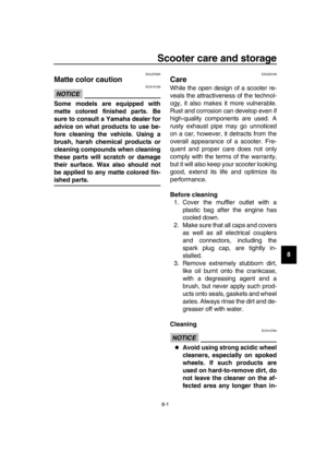 97
97 98
98 99
99 100
100 101
101 102
102 103
103 104
104 105
105 106
106 107
107 108
108 109
109