Page 65 of 110
Periodic maintenance and adjustment
7-8
1
2
3
4
5
6
7
8
9
10
11
12
13
14
3. Remove the panel as shown.
To install the panel
1. Insert the tabs on the upper left and right sides of the panel.
2. Align the center and lower projec- tions and then push the panel into
its original position. 3. Install the quick fastener.
Panel C
To remove the panel
Remove the screws, and then pull the
panel backward and upward.
To install the panel
Place the panel in the original position,
and then install the screws.
Panel D
To remove the panel
Remove the screws, and then pull the
panel outward.
1. Screw
2. Panel C
2
1
2PW-9-E1.book 8 ページ 2015年9月10日 木曜日 午後5時17分
Page 66 of 110

Periodic maintenance and adjustment
7-9
1
2
3
4
5
6
7
8
9
10
11
12
13
14 To install the panel
Place the panel in the original position,
and then install the screws.
EAU19643
Checking the spark plugs
The spark plugs are important engine
components, which should be checked
periodically, preferably by a Yamaha
dealer. Since heat and deposits will
cause any spark plug to slowly erode,
they should be removed and checked
in accordance with the periodic mainte-
nance and lubrication
chart. In addition,
the condition of the spark plugs can re-
veal the condition of the engine.
The porcelain insulator around the cen-
ter electrode of each spark plug should
be a medium-to-light tan (the ideal color
when the vehicle is ridden normally),
and all spark plugs installed in the en-
gine should have the same color. If any
spark plug shows a distinctly different
color, the engine could be operating im-
properly. Do not attempt to diagnose
such problems yourself. Instead, have
a Yamaha dealer check the vehicle.
If a spark plug shows signs of electrode
erosion and excessive carbon or other
deposits, it should be replaced.
Before installing a spark plug, the spark
plug gap should be measured with a
wire thickness gauge and, if necessary,
adjusted to specification.
1. Screw
2. Panel D
1
2
1
Specified spark plug:
NGK/CR7E
2PW-9-E1.book 9 ページ 2015年9月10日 木曜日 午後5時17分
Page 67 of 110

Periodic maintenance and adjustment
7-10
1
2
3
4
5
6
7
8
9
10
11
12
13
14
Clean the surface of the spark plug
gasket and its mating surface, and then
wipe off any grime from the spark plug
threads.
TIP
If a torque wrench is not available when
installing a spark plug, a good estimate
of the correct torque is 1/4–1/2 turn
past finger tight. However, the spark
plug should be tightened to the speci-
fied torque as soon as possible.
EAU1985E
Engine oil and oil filter
cartridge
The engine oil level should be checked
before each ride. In addition, the oil
must be changed and the oil filter car-
tridge replaced at the intervals speci-
fied in the periodic maintenance and
lubrication chart.
To check the engine oil level
1. Place the vehicle on the center- stand. A slight tilt to the side can
result in a false reading.
2. Start the engine, warm it up for two minutes, and then turn it off.
NOTICE
ECA11291
The engine must be cold before pro-
ceeding with the oil level check, oth-
erwise the check will result in a false
reading.
3. Wait two minutes until the oil set- tles, and then check the oil level
through the check window located
at the bottom-left side of the crank-
case.
TIP
The engine oil should be between the
minimum and maximum level marks.
1. Spark plug gap
Spark plug gap:0.7–0.8 mm (0.028–0.031 in)
Tightening torque: Spark plug:
13 Nm (1.3 m·kgf, 9.4 ft·lbf)
2PW-9-E1.book 10 ページ 2015年9月10日 木曜日 午後5時17分
Page 68 of 110

Periodic maintenance and adjustment
7-11
1
2
3
4
5
6
7
8
9
10
11
12
13
14 4. If the engine oil is below the mini-
mum level mark, add sufficient oil
of the recommended type to raise
it to the correct level.
To change the engine oil (with or
without oil filter cartridge replace-
ment) 1. Place the vehicle on a level sur- face.
2. Start the engine, warm it up for several minutes, and then turn it
off.
3. Place an oil pan under the engine to collect the used oil.
4. Remove the engine oil filler cap, the engine oil drain bolt and its
gasket to drain the oil from the
crankcase. 5. Check the O-ring for damage and
replace it if necessary.
TIP
Skip steps 6–8 if the oil filter cartridge is
not being replaced.
6. Remove the oil filter cartridge with an oil filter wrench.
1. Engine oil level check window
2. Maximum level mark
3. Minimum level mark
1. Engine oil filler cap
1
23
1
1. Engine oil drain bolt
2. O-ring
3. Gasket
1. Engine oil drain bolt
2. O-ring
1 2
3
1 2
2PW-9-E1.book 11 ページ 2015年9月10日 木曜日 午後5時17分
Page 69 of 110

Periodic maintenance and adjustment
7-12
1
2
3
4
5
6
7
8
9
10
11
12
13
14
TIP
An oil filter wrench is available at a
Yamaha dealer. 7. Apply a thin coat of clean engine oil to the O-ring of the new oil filter
cartridge.
TIP
Make sure that the O-ring is properly
seated.
8. Install the new oil filter cartridge, and then tighten it to the specified
torque with a torque wrench. 9. Install the engine oil drain bolt and
its new gasket, and then tighten
the bolt to the specified torque.
10. Refill with the specified amount of the recommended engine oil, and
then install and tighten the oil filler
cap.
TIP
Be sure to wipe off spilled oil on any
parts after the engine and exhaust sys-
tem have cooled down.
NOTICE
ECA11621
In order to prevent clutch slip-
page (since the engine oil also
1. Oil filter wrench
2. Oil filter cartridge
1. O-ring
2
1
1
1. Torque wrench
Tightening torque:
Oil filter cartridge:
17 Nm (1.7 m·kgf, 12 ft·lbf)
Tightening torque: Engine oil drain bolt: 43 Nm (4.3 m·kgf, 31 ft·lbf)
Recommended engine oil: See page 9-1.
Oil quantity: Oil change: 2.70 L (2.85 US qt, 2.38 Imp.qt)
With oil filter removal: 2.90 L (3.07 US qt, 2.55 Imp.qt)
1
2PW-9-E1.book 12 ページ 2015年9月10日 木曜日 午後5時17分
Page 70 of 110
, do not
mix any chemical additives. Do
not use oils with a diesel speci-
fication of “CD” or oils o")
Periodic maintenance and adjustment
7-13
1
2
3
4
5
6
7
8
9
10
11
12
13
14 lubricates the clutch), do not
mix any chemical additives. Do
not use oils with a diesel speci-
fication of “CD” or oils of a high-
er quality than specified. In
addition, do not use oils labeled
“ENERGY CONSERVING II” or
higher.
Make sure that no foreign mate-
rial enters the crankcase.
11. Start the engine, and then let it idle for several minutes while checking
it for oil leakage. If oil is leaking, im-
mediately turn the engine off and
check for the cause.
12. Turn the engine off, and then check the oil level and correct it if
necessary.
13. Reset the oil change indicator. (See page 4-6.)
TIP
If the engine oil is changed before the
oil change indicator comes on (i.e. be-
fore the periodic oil change interval has
been reached), the indicator must be
reset after the oil change for the next
periodic oil change to be indicated at
the correct time.
EAU20071
Coolant
The coolant level should be checked
before each ride. In addition, the cool-
ant must be changed at the intervals
specified in the periodic maintenance
and lubrication chart.
EAU52024To check the coolant level1. Place the vehicle on the center- stand.
TIP
The coolant level must be checked
on a cold engine since the level
varies with engine temperature.
Make sure that the vehicle is posi-
tioned straight up when checking
the coolant level. A slight tilt to the
side can result in a false reading.
2. Check the coolant level through the check window.
TIP
The coolant should be between the
minimum and maximum level marks.
3. If the coolant is at or below the minimum level mark, remove the
left floorboard mat by pulling it up.
1. Coolant level check window
2. Maximum level mark
3. Minimum level mark
12
3
2PW-9-E1.book 13 ページ 2015年9月10日 木曜日 午後5時17分
Page 71 of 110

Periodic maintenance and adjustment
7-14
1
2
3
4
5
6
7
8
9
10
11
12
13
14
4. Remove the coolant reservoir cov-
er by removing the screw.
5. Remove the coolant reservoir cap, add coolant to the maximum level
mark, and then install the reservoir
cap. WARNING! Remove only
the coolant reservoir cap. Never
attempt to remove the radiator
cap when the engine is
hot.
[EWA15162] NOTICE: If coolant is
not available, use distilled water
or soft tap water instead. Do not
use hard water or salt water
since it is harmful to the engine.
If water has been used instead
of coolant, replace it with cool-
ant as soon as possible, other-
wise the cooling system will not
be protected against frost and corrosion. If water has been
added to the coolant, have a
Yamaha dealer check the anti-
freeze content of the coolant as
soon as possible, otherwise the
effectiveness of the coolant will
be reduced.
[ECA10473]
6. Install the coolant reservoir cover
by installing the screw.
7. Place the left floorboard mat in the original position and push it down-
ward to secure it.
1. Floorboard mat
1. Coolant reservoir cover
2. Screw
1
1 2
1. Coolant reservoir cap
Coolant reservoir capacity (up to the
maximum level mark):
0.27 L (0.29 US qt, 0.24 Imp.qt)
1
2PW-9-E1.book 14 ページ 2015年9月10日 木曜日 午後5時17分
Page 72 of 110

Periodic maintenance and adjustment
7-15
1
2
3
4
5
6
7
8
9
10
11
12
13
14
EAU52031
Replacing the air filter element
The air filter element should be re-
placed at the intervals specified in the
periodic maintenance and lubrication
chart. Replace the air filter element
more frequently if you are riding in un-
usually wet or dusty areas.
To replace the air filter element 1. Remove panel C. (See page 7-7.)
2. Remove the air filter case cover by removing the screws.
3. Pull the air filter element out.
4. Insert a new air filter element into the air filter case. NOTICE: Make
sure that the air filter element is
properly seated in the air filter
case. The engine should never
be operated without the air filter element installed, otherwise the
piston(s) and/or cylinder(s) may
become excessively worn.[ECA10482]
5. Install the air filter case cover by in-
stalling the screws.
6. Install the panel.
1. Screw
2. Air filter case cover
1. Air filter element
1
1 2
1
2PW-9-E1.book 15 ページ 2015年9月10日 木曜日 午後5時17分
 1
1 2
2 3
3 4
4 5
5 6
6 7
7 8
8 9
9 10
10 11
11 12
12 13
13 14
14 15
15 16
16 17
17 18
18 19
19 20
20 21
21 22
22 23
23 24
24 25
25 26
26 27
27 28
28 29
29 30
30 31
31 32
32 33
33 34
34 35
35 36
36 37
37 38
38 39
39 40
40 41
41 42
42 43
43 44
44 45
45 46
46 47
47 48
48 49
49 50
50 51
51 52
52 53
53 54
54 55
55 56
56 57
57 58
58 59
59 60
60 61
61 62
62 63
63 64
64 65
65 66
66 67
67 68
68 69
69 70
70 71
71 72
72 73
73 74
74 75
75 76
76 77
77 78
78 79
79 80
80 81
81 82
82 83
83 84
84 85
85 86
86 87
87 88
88 89
89 90
90 91
91 92
92 93
93 94
94 95
95 96
96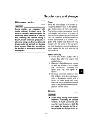 97
97 98
98 99
99 100
100 101
101 102
102 103
103 104
104 105
105 106
106 107
107 108
108 109
109