Page 81 of 110
Periodic maintenance and adjustment
7-24
1
2
3
4
5
6
7
8
9
10
11
12
13
14
EAU51991
Drive belt slack
The drive belt slack should be checked
and adjusted by a Yamaha dealer at
the intervals specified in the periodic
maintenance and lubrication chart.
EAU23098
Checking and lubricating the
cables
The operation of all control cables and
the condition of the cables should be
checked before each ride, and the ca-
bles and cable ends should be lubricat-
ed if necessary. If a cable is damaged
or does not move smoothly, have a
Yamaha dealer check or replace it.
WARNING! Damage to the outer
housing of cables may result in in-
ternal rusting and cause interfer-
ence with cable movement. Replace
damaged cables as soon as possi-
ble to prevent unsafe condi-
tions.
[EWA10712]
Recommended lubricant: Yamaha cable lubricant or other suit-
able cable lubricant
2PW-9-E1.book 24 ページ 2015年9月10日 木曜日 午後5時17分
Page 82 of 110

Periodic maintenance and adjustment
7-25
1
2
3
4
5
6
7
8
9
10
11
12
13
14
EAU23115
Checking and lubricating the
throttle grip and cable
The operation of the throttle grip should
be checked before each ride. In addi-
tion, the cable should be lubricated by a
Yamaha dealer at the intervals speci-
fied in the periodic maintenance chart.
The throttle cable is equipped with a
rubber cover. Make sure that the cover
is securely installed. Even though the
cover is installed correctly, it does not
completely protect the cable from water
entry. Therefore, use care not to pour
water directly onto the cover or cable
when washing the vehicle. If the cable
or cover becomes dirty, wipe clean with
a moist cloth.
EAU23173
Lubricating the fr ont and rear
brake levers
Front brake lever
Rear brake lever
The pivoting points of the front and rear
brake levers must be lubricated at the
intervals specified in the periodic main-
tenance and lubrication chart.
Recommended lubricant: Silicone grease
2PW-9-E1.book 25 ページ 2015年9月10日 木曜日 午後5時17分
Page 83 of 110

Periodic maintenance and adjustment
7-26
1
2
3
4
5
6
7
8
9
10
11
12
13
14
EAU23215
Checking and l ubricating the
centerstand and sidestand
The operation of the centerstand and
sidestand should be checked before
each ride, and the pivots and metal-to-
metal contact surfaces should be lubri-
cated if necessary.
WARNING
EWA10742
If the centerstand or sidestand does
not move up and down smoothly,
have a Yamaha dealer check or re-
pair it. Otherwise, the centerstand or
sidestand could contact the ground
and distract the operator, resulting
in a possible loss of control.
EAU23273
Checking the front fork
The condition and operation of the front
fork must be checked as follows at the
intervals specified in the periodic main-
tenance and lubrication chart.
To check the condition
Check the inner tubes for scratches,
damage and excessive oil leakage.
To check the operation
1. Place the vehicle on a level sur- face and hold it in an upright posi-
tion. WARNING! To avoid injury,
securely support the vehicle so
there is no danger of it falling
over.
[EWA10752]
2. While applying the front brake, push down hard on the handlebars
several times to check if the front
fork compresses and rebounds
smoothly.
NOTICE
ECA10591
If any damage is found or the front
fork does not operate smoothly,
have a Yamaha dealer check or re-
pair it.Recommended lubricant:Lithium-soap-based grease
2PW-9-E1.book 26 ページ 2015年9月10日 木曜日 午後5時17分
Page 84 of 110
Periodic maintenance and adjustment
7-27
1
2
3
4
5
6
7
8
9
10
11
12
13
14
EAU45512
Checking the steering
Worn or loose steering bearings may
cause danger. Therefore, the operation
of the steering must be checked as fol-
lows at the intervals specified in the pe-
riodic maintenance and lubrication
chart. 1. Place the vehicle on the center- stand. WARNING! To avoid inju-
ry, securely support the vehicle
so there is no danger of it falling
over.
[EWA10752]
2. Hold the lower ends of the front fork legs and try to move them for-
ward and backward. If any free
play can be felt, have a Yamaha
dealer check or repair the steering.
EAU23292
Checking the wheel bearings
The front and rear wheel bearings must
be checked at the intervals specified in
the periodic maintenance and lubrica-
tion chart. If there is play in the wheel
hub or if the wheel does not turn
smoothly, have a Yamaha dealer check
the wheel bearings.
2PW-9-E1.book 27 ページ 2015年9月10日 木曜日 午後5時17分
Page 85 of 110

This model is equipped with a VR")
Periodic maintenance and adjustment
7-28
1
2
3
4
5
6
7
8
9
10
11
12
13
14
EAU63751
Battery
The battery is located behind the auxil-
iary DC connector. (See page 4-24.)
This model is equipped with a VRLA
(Valve Regulated Lead Acid) battery.
There is no need to check the electro-
lyte or to add distilled water. However,
the battery lead connections need to be
checked and, if necessary, tightened.
WARNING
EWA10761
Electrolyte is poisonous and
dangerous since it contains sul-
furic acid, which causes severe
burns. Avoid any contact with
skin, eyes or clothing and al-
ways shield your eyes when
working near batteries. In case
of contact, administer the fol-
lowing FIRST AID. EXTERNAL: Flush with plenty of water.
INTERNAL: Drink large quan- tities of water or milk and im-
mediately call a physician.
EYES: Flush with water for 15 minutes and seek prompt
medical attention.
Batteries produce explosive hy- drogen gas. Therefore, keep
sparks, flames, cigarettes, etc.,
away from the battery and pro-
vide sufficient ventilation when
charging it in an enclosed
space.
KEEP THIS AND ALL BATTER-
IES OUT OF THE REACH OF
CHILDREN.
To charge the battery
Have a Yamaha dealer charge the bat-
tery as soon as possible if it seems to
have discharged. Keep in mind that the
battery tends to discharge more quickly
if the vehicle is equipped with optional
electrical accessories.
NOTICE
ECA16522
To charge a VRLA (Valve Regulated
Lead Acid) battery, a special (con-
stant-voltage) battery charger is re-
quired. Using a conventional battery
charger will damage the battery.
To store the battery 1. If the vehicle will not be used for more than one month, remove the
battery, fully charge it, and then
place it in a cool, dry place.
NOTICE: When removing the
battery, be sure turn the vehicle
power off, then disconnect the
negative lead before discon-
necting the positive lead.
[ECA21900]
2. If the battery will be stored for morethan two months, check it at least
once a month and fully charge it if
necessary.
3. Fully charge the battery before in- stallation. NOTICE: When install-
1. Negative battery lead (black)
2. Positive battery lead (red)
3. Battery
2
3 1
2PW-9-E1.book 28 ページ 2015年9月10日 木曜日 午後5時17分
Page 86 of 110
Periodic maintenance and adjustment
7-29
1
2
3
4
5
6
7
8
9
10
11
12
13
14 ing the battery, connect the
positive lead before connecting
the negative lead.
[ECA21910]
4. After installation, make sure that
the battery leads are properly con-
nected to the battery terminals.
NOTICE
ECA16531
Always keep the battery charged.
Storing a discharged battery can
cause permanent battery damage.
EAU54025
Replacing the fuses
The main fuse box and the fuse box,
which contains the fuses for the individ-
ual circuits, are located under panel B.
(See page 7-7.)
If a fuse is blown, replace it as follows.1. Turn the vehicle power off.
2. Remove the blown fuse, and then install a new fuse of the specified
amperage. WARNING! Do not
use a fuse of a higher amperage
rating than recommended to
avoid causing extensive dam-
age to the electrical system and
possibly a fire.
[EWA15132]
For XP500
1. Main fuse
2. Spare main fuse
3. Main fuse box cover
1
2
3
2PW-9-E1.book 29 ページ 2015年9月10日 木曜日 午後5時17分
Page 87 of 110

Periodic maintenance and adjustment
7-30
1
2
3
4
5
6
7
8
9
10
11
12
13
14
For XP500
For XP500A
For XP500A
3. Turn the vehicle power on and turn on the electrical circuit in question
to check if the device operates.
4. If the fuse immediately blows
1. Signaling system fuse
2. Ignition fuse
3. Parking lighting fuse
4. Radiator fan motor fuse
5. Fuel injection system fuse
6. Backup fuse
7. Spare fuse
8. Auxiliary DC jack fuse
9. Headlight fuse
1. Main fuse
2. Spare main fuse
3. Main fuse box cover
4. Signaling system fuse
5. Ignition fuse
6. Parking lighting fuse
7. Radiator fan motor fuse
8. Fuel injection system fuse
9. Backup fuse
10.Spare fuse
1
2
3
4
5
6
7
7
7 8 9
7
2
3
4 5
6
7
8
9
10
1
1. Spare fuse
2. ABS solenoid fuse
3. ABS motor fuse
4. Headlight fuse
5. ABS control unit fuse
6. Auxiliary DC jack fuse
Specified fuses:
Main fuse: 40.0 A
Headlight fuse: 10.0 A
Signaling system fuse: 15.0 A
Ignition fuse:
7.5 A
Radiator fan motor fuse: 15.0 A
Fuel injection system fuse: 7.5 A
Parking lighting fuse:
10.0 A
ABS control unit fuse: 7.5 A (XP500A)
ABS motor fuse: 30.0 A (XP500A)
ABS solenoid fuse:
15.0 A (XP500A)
Backup fuse: 7.5 A
Auxiliary DC jack fuse: 5.0 A
1
2
4 3
5
6
2PW-9-E1.book 30 ページ 2015年9月10日 木曜日 午後5時17分
Page 88 of 110
Periodic maintenance and adjustment
7-31
1
2
3
4
5
6
7
8
9
10
11
12
13
14 again, have a Yamaha dealer
check the electrical system.
EAU64070
Headlights
This model is equipped with LED-type
headlights.
If a headlight does not come on, have a
Yamaha dealer check its electrical cir-
cuit.
NOTICE
ECA16581
Do not affix any type of tinted film or
stickers to the headlight lens.
2PW-9-E1.book 31 ページ 2015年9月10日 木曜日 午後5時17分
 1
1 2
2 3
3 4
4 5
5 6
6 7
7 8
8 9
9 10
10 11
11 12
12 13
13 14
14 15
15 16
16 17
17 18
18 19
19 20
20 21
21 22
22 23
23 24
24 25
25 26
26 27
27 28
28 29
29 30
30 31
31 32
32 33
33 34
34 35
35 36
36 37
37 38
38 39
39 40
40 41
41 42
42 43
43 44
44 45
45 46
46 47
47 48
48 49
49 50
50 51
51 52
52 53
53 54
54 55
55 56
56 57
57 58
58 59
59 60
60 61
61 62
62 63
63 64
64 65
65 66
66 67
67 68
68 69
69 70
70 71
71 72
72 73
73 74
74 75
75 76
76 77
77 78
78 79
79 80
80 81
81 82
82 83
83 84
84 85
85 86
86 87
87 88
88 89
89 90
90 91
91 92
92 93
93 94
94 95
95 96
96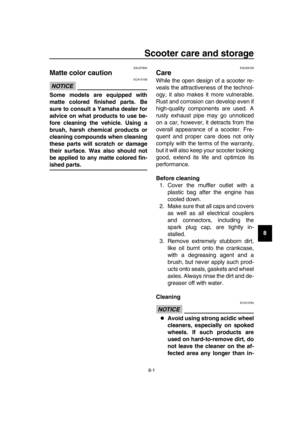 97
97 98
98 99
99 100
100 101
101 102
102 103
103 104
104 105
105 106
106 107
107 108
108 109
109

![YAMAHA TMAX 2016 Owners Manual Periodic maintenance and adjustment
7-29
1
2
3
4
5
6
7
8
9
10
11
12
13
14 ing the battery, connect the
positive lead before connecting
the negative lead.
[ECA21910]
4. After installation, make sure th](/manual-img/51/51478/w960_51478-85.png "YAMAHA TMAX 2016 Owners Manual Periodic maintenance and adjustment
7-29
1
2
3
4
5
6
7
8
9
10
11
12
13
14 ing the battery, connect the
positive lead before connecting
the negative lead.
[ECA21910]
4. After installation, make sure th")
