Page 25 of 96

Instrument and control functions
3-10
3 To adjust the brightness
1. Push the “RES” button to select
the desired shift indicator light
brightness level.
2. Push the “SEL” button to confirm
the selected brightness level. The
display exits the shift timing light
control mode and returns to the
standard multi-function display
mode.
Self-diagnosis device
This model is equipped with a self-di-
agnosis device for various electrical
circuits.If a problem is detected in any of those
circuits, the engine trouble warning
light will come on and the display will
indicate an error code.
NOTICE
ECA11591
If the display indicates an error
code, the vehicle should be checked
as soon as possible in order to avoid
engine damage.
EAU1234H
Handlebar switchesLeft
Right
1. Engine trouble warning light “ ”
2. Error code display
2
1
1.
2. Dimmer switch / Ž
3. Turn signal switch / Ž
4. Horn switch Ž
1. Engine stop switch / Ž
2. Start switch Ž
4312
21
UB04E0E0.book Page 10 Wednesday, September 2, 2015 3:51 PM
Page 26 of 96

Instrument and control functions
3-11
3
EAU12361
Pass switch “PASS”
Press this switch to flash the headlight.
EAU62540
Dimmer switch “ / ”
Set this switch to “ ” for the high
beam and to “ ” for the low beam.TIPWhen the switch is set to low beam,
only the right headlight bulb comes on.
When the switch is set to high beam,
both headlight bulbs come on.
EAU12461
Turn signal switch “ / ”
To signal a right-hand turn, push this
switch to “ ”. To signal a left-hand
turn, push this switch to “ ”. When
released, the switch returns to the cen-
ter position. To cancel the turn signal
lights, push the switch in after it has re-
turned to the center position.
EAU12501
Horn switch “ ”
Press this switch to sound the horn.
EAU12661
Engine stop switch “ / ”
Set this switch to “ ” before starting
the engine. Set this switch to “ ” to
stop the engine in case of an emergen-
cy, such as when the vehicle overturns
or when the throttle cable is stuck.
EAU12713
Start switch “ ”
Push this switch to crank the engine
with the starter. See page 5-1 for start-
ing instructions prior to starting the en-
gine.
EAU62500
The engine trouble warning light will
come on when the key is turned to “ ”
and the start switch is pushed, but this
does not indicate a malfunction.
EAU12822
Clutch leverThe clutch lever is located on the left
side of the handlebar. To disengage
the clutch, pull the lever toward the
handlebar grip. To engage the clutch,
release the lever. The lever should be
pulled rapidly and released slowly for
smooth clutch operation.
The clutch lever is equipped with a
clutch switch, which is part of the igni-
tion circuit cut-off system. (See page
3-20.)1. Clutch lever1
UB04E0E0.book Page 11 Wednesday, September 2, 2015 3:51 PM
Page 27 of 96
Instrument and control functions
3-12
3
EAU12872
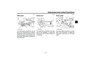
Shift pedalThe shift pedal is located on the left
side of the motorcycle and is used in
combination with the clutch lever when
shifting the gears of the 6-speed con-
stant-mesh transmission equipped on
this motorcycle.
EAU12892
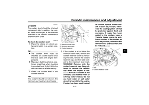
Brake leverThe brake lever is located on the right
side of the handlebar. To apply the
front brake, pull the lever toward the
throttle grip.
EAU12944
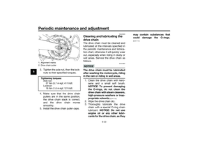
Brake pedalThe brake pedal is located on the right
side of the motorcycle. To apply the
rear brake, press down on the brake
pedal.
1. Shift pedal
1
1. Brake lever
1
1. Brake pedal
1
UB04E0E0.book Page 12 Wednesday, September 2, 2015 3:51 PM
Page 28 of 96

Instrument and control functions
3-13
3
EAU13075
Fuel tank capTo open the fuel tank cap
Open the fuel tank cap lock cover, in-
sert the key into the lock, and then turn
it 1/4 turn clockwise. The lock will be
released and the fuel tank cap can be
opened.
To close the fuel tank cap
1. Push the fuel tank cap into posi-
tion with the key inserted in the
lock.
2. Turn the key counterclockwise to
the original position, remove it,
and then close the lock cover.
TIPThe fuel tank cap cannot be closed un-
less the key is in the lock. In addition,
the key cannot be removed if the cap is
not properly closed and locked.
WARNING
EWA11092
Make sure that the fuel tank cap is
properly closed after filling fuel.
Leaking fuel is a fire hazard.
EAU13222
FuelMake sure there is sufficient gasoline in
the tank.
WARNING
EWA10882
Gasoline and gasoline vapors are
extremely flammable. To avoid fires
and explosions and to reduce the
risk of injury when refueling, follow
these instructions.1. Before refueling, turn off the en-
gine and be sure that no one is sit-
ting on the vehicle. Never refuel
while smoking, or while in the vi-
cinity of sparks, open flames, or
other sources of ignition such as
the pilot lights of water heaters
and clothes dryers.
2. Do not overfill the fuel tank. When
refueling, be sure to insert the
pump nozzle into the fuel tank filler
hole. Stop filling when the fuel
reaches the bottom of the filler
tube. Because fuel expands when
it heats up, heat from the engine or
the sun can cause fuel to spill out
of the fuel tank.
1. Fuel tank cap lock cover
2. Unlock.
1 2
UB04E0E0.book Page 13 Wednesday, September 2, 2015 3:51 PM
Page 29 of 96

Instrument and control functions
3-14
3
3. Wipe up any spilled fuel immedi-
ately. NOTICE: Immediately
wipe off spilled fuel with a clean,
dry, soft cloth, since fuel may
deteriorate painted surfaces or
plastic parts.
[ECA10072]
4. Be sure to securely close the fuel
tank cap.
WARNING
EWA15152
Gasoline is poisonous and can
cause injury or death. Handle gaso-
line with care. Never siphon gasoline
by mouth. If you should swallow
some gasoline or inhale a lot of gas-
oline vapor, or get some gasoline in
your eyes, see your doctor immedi-ately. If gasoline spills on your skin,
wash with soap and water. If gaso-
line spills on your clothing, change
your clothes.
EAU49743
NOTICE
ECA11401
Use only unleaded gasoline. The use
of leaded gasoline will cause severe
damage to internal engine parts,
such as the valves and piston rings,
as well as to the exhaust system.Your Yamaha engine has been de-
signed to use regular unleaded gaso-
line with a research octane number of
95 or higher. If knocking (or pinging)
occurs, use a gasoline of a differentbrand or premium unleaded fuel. Use
of unleaded fuel will extend spark plug
life and reduce maintenance costs.
Gasohol
There are two types of gasohol: gaso-
hol containing ethanol and that con-
taining methanol. Gasohol containing
ethanol can be used if the ethanol con-
tent does not exceed 10% (E10). Gas-
ohol containing methanol is not
recommended by Yamaha because it
can cause damage to the fuel system
or vehicle performance problems.
1. Fuel tank filler tube
2. Maximum fuel level
2
1
Recommended fuel:
Regular unleaded gasoline (Gasohol
[E10] acceptable)
Fuel tank capacity:
14 L (3.7 US gal, 3.1 Imp.gal)
Fuel reserve amount:
3.0 L (0.79 US gal, 0.66 Imp.gal)
UB04E0E0.book Page 14 Wednesday, September 2, 2015 3:51 PM
Page 30 of 96

Instrument and control functions
3-15
3
EAU51172
Fuel tank breather hose and
overflow hoseBefore operating the motorcycle:
Check each hose connection.
Check each hose for cracks or
damage, and replace if necessary.
Make sure that the end of each
hose is not blocked, and clean if
necessary.
EAU13434
Catalytic converterThis model is equipped with a catalytic
converter in the exhaust system.
WARNING
EWA10863
The exhaust system is hot after op-
eration. To prevent a fire hazard or
burns:
Do not park the vehicle near
possible fire hazards such as
grass or other materials that
easily burn.
Park the vehicle in a place
where pedestrians or children
are not likely to touch the hot
exhaust system.
Make sure that the exhaust sys-
tem has cooled down before
doing any maintenance work.
Do not allow the engine to idle
more than a few minutes. Long
idling can cause a build-up of
heat.
NOTICE
ECA10702
Use only unleaded gasoline. The use
of leaded gasoline will cause unre-
pairable damage to the catalytic
converter.
1. Fuel tank overflow hose
2. Fuel tank breather hose
2
1
UB04E0E0.book Page 15 Wednesday, September 2, 2015 3:51 PM
Page 31 of 96
Instrument and control functions
3-16
3
EAU62622
SeatsPassenger seat
To remove the passenger seat1. Insert the key into the seat lock,
and then turn it clockwise.
2. While holding the key in that posi-
tion, lift the rear of the passenger
seat and pull it backward.To install the passenger seat
1. Insert the projections on the front
of the passenger seat into the seat
holders as shown, and then push
the rear of the seat down to lock it
in place.
2. Remove the key.
Rider seat
To remove the rider seat1. Remove the passenger seat.
2. Remove the center cover by re-
moving the screws.3. Remove the rider seat by remov-
ing the bolts. Lift the rear of the
rider seat and pull it backward.
1. Passenger seat lock
2. Unlock.
1
2
1. Projection
2. Seat holder
1
2
1. Center cover
2. Screw
1. Rider seat
2. Bolt
12
12
UB04E0E0.book Page 16 Wednesday, September 2, 2015 3:51 PM
Page 32 of 96

Instrument and control functions
3-17
3To install the rider seat
1. Insert the projection on the front of
the rider seat into the seat holder
as shown, and then place the seat
in the original position.
2. Install the rider seat bolts.
3. Install the center cover by install-
ing the screws.
4. Install the passenger seat.TIPMake sure that the seats are properly
secured before riding.
EAU62930
Helmet holdersThe helmet holders are located on the
bottom of the passenger seat.
To secure a helmet to a helmet hold-
er
1. Remove the passenger seat. (See
page 3-16.)
2. Attach a helmet to a helmet hold-
er, and then securely install the
passenger seat. WARNING! Nev-
er ride with a helmet attached to
the helmet holder, since the hel-
met may hit objects, causing
loss of control and possibly an
accident.
[EWA10162]
To release a helmet from a helmet
holder
Remove the passenger seat, remove
the helmet from the helmet holder, and
then install the seat.
1. Projection
2. Seat holder
1
2
1. Helmet holder
1
1. Helmet
2. Passenger seat
21
UB04E0E0.book Page 17 Wednesday, September 2, 2015 3:51 PM